Advertisement
Quick Links
USER MANUAL
# 90750
BRUSHLESS + BRUSHED
over 3T (brushless - star)
over 4T (brushed)
for distributor address see packaging
1. INSTALLATION
The NOSRAM MATRIX EVOLUTION ISTC is supplied with 12AWG power-wires without connectors. Be very
careful with the correct wire sequence/colors since an incorrect connection may damage the speed-cont-
rol! Avoid creating solder bridges on the solder-tabs and isolate all connections carefully.
Caution: Avoid soldering longer then 5sec per soldering joint when replacing the power wires on the speed-
control and motor to prevent possible damage due to overheating of the components!
• Connect the speed-control to the receiver (position: Channel 2)
BRUSHLESS MOTOR:
• Blue power-wire
Speedo MOT.A to motor „A"
• Yellow power-wire
Speedo MOT.B to motor „B"
• Orange power-wire
Speedo MOT.C to motor „C"
• Connect the hall sensor cable to the speed-control and the motor.
+
-
C
B
A
Hall Sensor Wire
BRUSHED MOTOR:
• Blue/Yellow power-wire
Speedo MOT.A/MOT.B to „Minus" on the motor.
• Orange power-wire
Speedo MOT.C to „Plus" on the motor.
+
-
C
B
A
Together to minus
• Doublecheck all connections before connecting the speed-control to a battery.
CAUTION: If battery is connected with reversed polarity it will destroy your speed-control!
• Red power-wire
Speedo BAT+ to battery „Plus"
• Black power-wire
Speedo BAT- to battery „Minus"
• The speed-control is now ready to be set-up (see section 6).
2. CONNECTIONS
On/Off
Switch
Receiver
wire
Power Capacitor
RECEIVER CONNECTING WIRE:
RECEIVER CONNECTING WIRE:
This NOSRAM speed-control is equipped with an NOSRAM Multicon
speed-control is equipped with an NOSRAM Multicon receiver
wire. As supplied, it will easily fit in all ordinary receivers.
HALL SENSOR WIRE:
This bi-directional multipole wire (which comes with the motor and NOT the speed-control!) connects the
speed-control and the motor. Do not alter or modify this cable! There are replaceable/optional hall sensor
wires available: • #92510 (20cm)
• #92520 (10cm)
POWER WIRES:
For maximum performance, 12AWG power wires without any connectors are used. The unique splitted
solder-tabs allow easy and convenient replacement of the power wires. Nevertheless some soldering skills
are required. Avoid soldering longer then 5sec per soldering joint to prevent possible damage to the speed-
control due to overheating of the components! There is a full 12awg replacement power wire set available:
#92506
RA00183
www.nosram.com
C
B
A
+
-
receiver
Hall Sensor
Hall Sensor
Connector
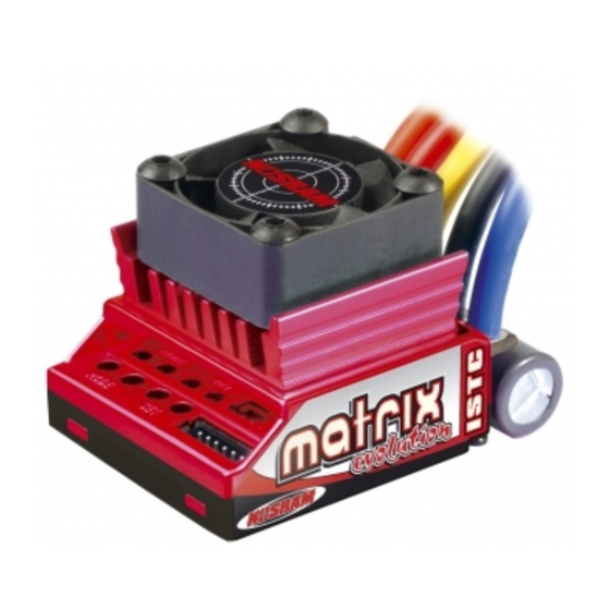
Dear Customer,
thank you for your trust in this NOSRAM product. By purchasing a NOSRAM MATRIX EVOLUTION ISTC
Brushless+Brushed speed-control, you have chosen one of the most advanced speed-controls of today.
This speed-control with all of its high-tech features and specially selected electronic components is one of
the best speed-controls for Touringcars currently available on the market.
• Optimized XPS.2 software
• Forward/Brake
• Automatic Brushless/Brushed adaption
• Launch Control
• 4, 5 and 6 cell optimized
Please read the following instructions to ensure, that your NOSRAM MATRIX EVOLUTION ISTC
Brushless+Brushed speed-control always works up to your full satisfaction.
Please read and understand these instructions completely before you use this product!
With operating this product, you accept the NOSRAM warranty terms.
3. SPECIFICATIONS
Brushless + Brushed
yes
Brushless + Brushed Adaption
AUTOMATIC
Forward/Reverse
yes
Case Size
33.1x37.6x32.5mm
Typ. Voltage Drop (Brushless)* @20A
0.017V / phase
Rated Current (Brushless)*
400A / phase
Compatible winding styles (Brushless)
Star
Rec. Motor Limit for Star winds (Brushless)**
for Star winds (Brushless)**
for
over 3 turns
Typ. Voltage Drop (Brushed)* @20A
0.012V
Rec. Motor Limit (Brushed)**
over 4 turns
Rated Current (Brushed)*
400A
4 adjustable Modes (NiMH/LiPo, XPS.2/PMS.2 Power Profiles, Initial- and Automaticbrake)
*
Transistors rating at 25°C junction temperature
** measured at 7.2V
4. INSTALLATION TIPS
• Mount the speedo using the supplied thick/black doubled-sided tape.
• Position the speed-control where it is protected in the event of a crash.
• Install the speed-control so that you have easy access to the connector and buttons.
• Make sure there is enough clearance (about 3cm) between the speed-control, power-wires, antenna
and receiver. Avoid any direct contact between power components, the receiver or the antenna. This can
cause interference. If interference occurs, position the components at a different place in the model.
• The aerial should be run vertically up and away from the receiver. Avoid contact with any parts made of
carbon fibre or metal. If the aerial is too long, don't coil up the excess length. It is better to cut it down
to a length of about 35 cm. See also the instructions supplied with your radio control system.
• Make sure there are enough cooling slits in the body. This will increase the performance and life of all the
electronic components.
HEATSINK: To achieve best perfomance even under extreme conditions, the heatsink has been directly
mounted to the speed-control. This ensures the best possible heat transfer away from the speed-control.
Caution: Never attempt to remove the heatsink, because the speed-control will get damaged if you do this.
The heatsink is an integral part of the speed-control and therefore cannot be removed.
Because of the physical principles of brushless technology, the speed-controls do get a little hotter then
brushed systems. Therefore it is required to let the speed-control cool down completely after every run.
5. SUPPRESSION
• Special TC software
• Low profile heatsink with integrated fan
• Smart-Temp-Readout-System
• Redesigned brake
• Large Power capacitor
Voltage Input
4.8-7.4V
Weight (excl. wires)
45.0g
B.E.C.
5.8V/3.0A
High Frequency
yes
Sensored Brushless System
yes
Multi-Protection-System
yes
Power Wires
12awg silicone flex
4, 5, 6 cell optimised
yes
Smart-Temp-Readout-System
yes
Launch Control
yes
Integrated heatsink + fan
yes
yes
Specifications subject to change without notice.
Mount the power-capacitor in a position
unt the power-capacitor in a position
where it is protec
where it is protected in the event of a crash.
The best place is right next to the speed-con-
he best place is right next to the speed-con-
trol (see picture)
trol (see picture). Secure it with doublesided
tape.
ONLY FOR BRUSHED MOTORS! Motors with no capa-
citors or not enough capacitors may interfere with the
speed-control. To avoid this, solder the supplied capaci-
tors to your motor (see picture).
Advertisement

Summary of Contents for Nosram MATRIX EVOLUTION ISTC
- Page 1 USER MANUAL Dear Customer, thank you for your trust in this NOSRAM product. By purchasing a NOSRAM MATRIX EVOLUTION ISTC Brushless+Brushed speed-control, you have chosen one of the most advanced speed-controls of today. RA00183 This speed-control with all of its high-tech features and specially selected electronic components is one of the best speed-controls for Touringcars currently available on the market.
- Page 2 6. RADIO / SPEED-CONTROL SET-UP 7. MODE PROGRAMMING In setup mode the NOSRAM MATRIX EVOLUTION ISTC stores every step when you press the SET button. All modes are available for brushless and brushed motors (speedo adapts automatically). The NOSRAM All the settings will be stored in the speed-controls memory even if the speed-control will be disconnected MATRIX EVOLUTION ISTC features 4 modes which enable you to adjust it to YOUR special requirements.
- Page 3 • Package your product carefully and include sales receipt and detailed description of malfunction. • Send parcel to your national NOSRAM distributor. By sending in this product, you assign NOSRAM to repair the product, if it is no warranty or Limited Lifetime • Distributor repairs or exchanges the product.
Need help?
Do you have a question about the MATRIX EVOLUTION ISTC and is the answer not in the manual?
Questions and answers