
Related Manuals for AC Tech SM004S


Summary of Contents for AC Tech SM004S
- Page 1 SCL/SCM Series Installation and Operation Manual Phone: 800.894.0412 - Fax: 888.723.4773 - Web: www.clrwtr.com - Email: info@clrwtr.com...
-
Page 2: Table Of Contents
Contents GENERAL . . . . . . . . . . . . . . . . . . . . . . . . . . . . . . . . . . . . . . . . . . . . . . . 2 1 .1 Products Covered in This Manual . - Page 3 10 .3 Surge Suppression on Relays . . . . . . . . . . . . . . . . . . . . . . . 15 10 .4 Start/Stop Control .
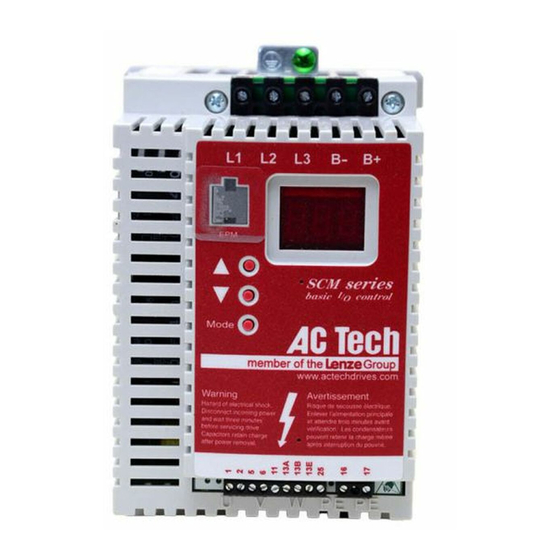
- Page 4 THE SCL/SCM SUB-MICRO DRIVE Input Power Terminals DC Bus Terminals (3 left terminals) (2 right terminals) Electronic Programming 3-Digit LED Display Module Programming Buttons Control Terminal Strip Output Motor Terminals Safety Information All safety information given in these Operating Instructions has the same layout: Signal Word! (characterizes the severity of the danger) Note (describes the danger and informs on how to proceed) Signal Words Icon DANGER! Warns of impending danger .
-
Page 5: General
This warranty is in lieu of all other warranties, expressed or implied. No other person, firm or corporation is authorized to assume, for Lenze AC Tech Corporation, any other liability in connection with the demonstration or sale of its products. - Page 6 INSTALLATION Ensure proper handling and avoid excessive mechanical stress . Do not bend any components and do not change any insulation distances during transport, handling, installation or maintenance . Do not touch any electronic components or contacts . This drive contains electrostatically sensitive components, which can easily be damaged by inappropriate handling . Static control precautions must be adhered to during installation, testing, servicing and repairing of this drive and associated options . Component damage may result if proper procedures are not followed . This drive has been tested by Underwriters Laboratory (UL) and is an approved component in compliance with UL508C Safety Standard . • Suitable for use on a circuit as described in Section 7 .0 of this manual . • Use minimum 75°C copper wire only .
-
Page 7: Customer Modification
The drive does feature many protection devices which are aimed at protecting the drive and the driven equipment by generating a fault and shutting the drive and motor down by removing power . Mains power variances can also result in shutdown of the drive . When the fault condition disappears or is cleared, the drive can be configured to automatically restart, it is the responsibility of the user, OEM and/or integrator to ensure that the drive is configured for safe operation . Customer Modification Lenze AC Tech Corporation, its sales representatives and distributors, welcome the opportunity to assist our customers in applying our products . Many custom options are available to aid in this function . Lenze AC Tech Corporation cannot assume responsibility for any modifications not authorized by its engineering department . SM01P Phone: 800.894.0412 - Fax: 888.723.4773 - Web: www.clrwtr.com - Email: info@clrwtr.com... -
Page 8: Scl/Scm Dimensions
If R = 6 .30" (160) S = 0 .28" (7) T = 0 .50" (13) Dia . Slot U = 0 .24" (6) V = 0 .90" (23) Mounting Tab Detail INPUT INPUT VOLTAGE PHASE MODEL MODEL SM004S 5.75 (146) 2.88 (74) 3.26 (83) 0.28 (7) 4.37 (111) 0.33 0.25 208 / 240 SM204S SL204S 5.75 (146) 2.88 (74) 3.26 (83) - Page 9 Dimensions for the SCL/SCM models rated 2 - 15Hp (1 .5 - 11kW) If R < 6 .30" (160) S = 0 .19" (5) T = 0 .38" (10) U = 0 .18" (5) V = 0 .66" (17) If R = 6 .30" (160) S = 0 .28" (7) T = 0 .50" (13) Dia . Slot U = 0 .24" (6) V = 0 .90" (23) Mounting Tab Detail INPUT INPUT VOLTAGE PHASE MODEL MODEL 208 / 240 SM220S SL220S 5.75 (146) 3.76 (95) 4.88 (124) 1.50 (38)
-
Page 10: Scl/Scm Model Designation Code
SCL/SCM MODEL DESIGNATION CODE The SCL/SCM model number gives a full description of the basic drive unit EXAMPLE: SL210S = SCL Series, 208/240 Vac, 1 HP, single phase input Series: SL = SCL Series Variable Speed AC Motor Drive with integral line filter SM = SCM Series Variable Speed AC Motor Drive Input Voltage: 0 = 120 Vac (For 110, 115, and 120 Vac; 50 or 60 Hz) 2 = 208/240 Vac (For 208, 220, 230, and 240 Vac;... -
Page 11: Scl/Scm Ratings
RATED (WATTS) INPUT CURRENT POWER CURRENT PHASE (AMPS) (kVA) (AMPS) 120 Vac INPUT MODELS 120 Vac 0 - 230 Vac SM004S N / A 0 .33 0 .25 6 .8 0 .8 1 .7 SM005S N / A 0 .50 0 .37 9 .2 1 .1... -
Page 12: Installation
INSTALLATION NOTE SCL/SCM Series drives are intended for inclusion within other equipment, by professional electrical installers according to EN 61000-3-2 . They are not intended for stand-alone operation . WARNING! Drives must not be installed where subjected to adverse environmental conditions such as: combustible, oily, or hazardous vapors or dust; excessive moisture or dirt; vibration; excessive ambient temperatures . Consult Lenze AC Tech for more information on the suitability of a drive to a particular environment . SCL/SCM models are suitable for UL Pollution Degree 2 environment only, and MUST be installed in an electrical enclosure that will provide complete mechanical protection and will maintain the internal temperature within the drive’s ambient operating temperature rating . All drive models MUST be mounted in a vertical position for proper heatsink cooling . Maintain a minimum spacing around the drive of at least 1 inch (25 mm) on each side and 2 inches (50 mm) on the top and bottom for units up to 5 Hp (4 kW), and 2 inches (50 mm) on each side and 4 inches (100 mm) on the top and bottom for larger units . Allow more... -
Page 13: Input Ac Power Requirements
INPUT AC POWER REQUIREMENTS DANGER! Hazard of electrical shock! Capacitors retain charge after power is removed . Before servicing the drive, disconnect incoming power and wait until the voltage between terminals B+ and B- is 0 VDC . The input voltage must match the nameplate voltage rating of the drive . Voltage fluctuation must not vary by greater than 10% overvoltage or 15% undervoltage . NOTE Drives with dual input voltage ratings must be programmed for the proper supply voltage (refer to Parameter 01 - LINE VOLTAGE SELECTION in Section 15, DESCRIPTION OF PARAMETERS) . The drive is suitable for use on a circuit capable of delivering not more than 5,000 RMS symmetrical amperes at the drive’s rated voltage . If the kVA rating of the AC supply transformer is greater than 10 times the input kVA rating of the drive(s), an isolation transformer or 2-3% input line reactor must be added to the line side of the drive(s) . Three phase voltage imbalance must be less than 2 .0% phase to phase . Excessive phase to phase imbalance can cause severe damage to the drive . -
Page 14: Input Fusing Requirements
A circuit breaker or a disconnect switch with fuses must be provided in accordance with the National Electric Code (NEC) and all local codes . Refer to the following tables for proper ratings: INPUT FUSE & CIRCUIT BREAKER RATINGS (for installation to UL and EN 60204-1) 120 Vac 1 phase 208/240 Vac 1 phase 208/240 Vac 3 phase 400/480 Vac 3 phase SM004S 10 A S_204S 10 A SM005S 15 A S_205S 10 A SM205... -
Page 15: Input Wire Size Requirements
INPUT WIRE SIZE REQUIREMENTS 120 Vac 1 phase 208/240 Vac 1 phase 208/240 Vac 3 phase 400/480 Vac 3 phase MODEL AWG mm MODEL AWG mm MODEL AWG mm MODEL AWG mm SM004S S_204S SM005S S_205S SM205 SM405 S_208S SM010S S_210S SM210 SM410... -
Page 16: Power Wiring
POWER WIRING DANGER! Hazard of electrical shock! Capacitors retain charge after power is removed . Before servicing the drive, disconnect the incoming power and wait until the voltage between terminals B+ and B- is 0 VDC . Note the drive input and output current ratings and the check applicable electrical codes for required wire type and size, grounding requirements, over-current protection, and incoming power disconnect, before wiring the drive . Size conservatively to minimize voltage drop . Input fusing and a power disconnect switch or contactor MUST be wired in series with terminals L1 and L2/N (on single-phase input models), or terminals L1, L2, and L3 (on three-phase input models) . This disconnect must be used to power down the drive when servicing, or when the drive is not to be operated for a long period of time, but should not be used to start and stop the motor . Repetitive cycling of a disconnect or input contactor (more than once every two minutes) may cause damage to the drive. Input and Output Wiring On single phase input models, wire the input power to terminals L1 and L2/N . On three phase input models, wire the input power to terminals L1, L2, and L3 . Refer to Section 9,... -
Page 17: Scl/Scm Power Wiring Diagram
SCL/SCM POWER WIRING DIAGRAM Input Input Input Single Phase Models Three Phase Models Three Phase Models 208/240V 7.5Hp and larger 208/240V up to 5Hp 400/480V up to 7.5Hp 400/480V 10Hp and larger Input AC Voltage PE lug on heatsink Input AC Voltage Input AC Voltage PE lug on heatsink L2/N... -
Page 18: Control Wiring
CONTROL WIRING 10.1 Control Wiring vs. Power Wiring External control wiring MUST be run in a separate conduit away from all other input and output power wiring . If control wiring is not kept separate from power wiring, electrical noise may be generated on the control wiring that will cause erratic drive behavior . Use twisted wires or shielded cable grounded at the drive chassis ONLY . Recommended control wire is Belden 8760 (2-wire), 8770 (3-wire), or equivalent . NOTE Control terminals provide basic isolation (insulation per EN 61800-5-1) . Protection against contact can only be assured by additional measures e .g . supplemental insulation . Strip off 0 .20 to 0 .25 inches (5 to 6 mm) of insulation for control wiring, and torque the control terminals to 2 lb-in (0 .2 Nm) . Be careful not to overtorque the control terminals, as this will cause damage to the terminal strip . This is not covered under warranty and can only be repaired by replacing the control board . -
Page 19: Speed Reference Selection
10.6 Speed Reference Selection If an analog speed reference input is used to control the drive speed, terminal TB-13A, 13B, or 13E (Parameter 10, 11, or 12) may be programmed as the input select for the desired analog input signal . When that TB-13 terminal is then closed to TB-11, the drive will follow the selected analog speed reference input . If an analog speed reference input is not selected on the terminal strip using TB-13A, 13B, or 13E, speed control will default to STANDARD mode, which is governed by the setting of STANDARD SPEED SOURCE (Parameter 05) . The STANDARD SPEED SOURCE can be the and buttons on the front of the drive, PRESET SPEED #1 (Parameter 31), a 0-10 VDC signal, or a 4-20 mA signal . 0 - 10 VDC and 4 - 20 mA INPUT SIGNALS TB-13A, TB-13B, and TB-13E can all be programmed to select a 0-10 VDC or 4-20 mA analog speed reference input . PRESET SPEEDS TB-13A can be programmed to select PRESET SPEED #1 (04), TB-13B to select PRESET SPEED #2 (04), and TB-13E to select PRESET SPEED #3 (04) . There are a total of seven preset speeds, which are activated by different combinations of contact closures between TB-13A, 13B, 13E and TB-11 . Refer to Parameters 31-37 in Section 15, DESCRIPTION OF PARAMETERS . -
Page 20: Drive Status Digital Outputs
NOTE If TB-13A, TB-13B, and TB-13E are all programmed to select speed references, and two or three of the terminals are closed to TB-11, the higher terminal has priority and will override the others . For example, if TB-13A is programmed to select 0-10VDC, and TB-13E is programmed to select PRESET SPEED #3, closing both terminals to TB-11 will cause the drive to respond to PRESET SPEED #3, because TB-13E overrides TB-13A . The exception to this is the MOP function, which requires the use of TB-13B and TB- 13E . This leaves TB-13A to be used for some other function . If TB-13A is programmed for a speed reference, and TB-13A is closed to TB-11, TB-13A will override the MOP function . 10.7 Drive Status Digital Outputs There is one Form A relay at terminals TB-16 and TB-17 . The relay contacts are rated 3 amps at 250 Vac . Terminal TB-13E can also be configured as a digital output . This output circuit is a current- sourcing type rated at 12 VDC and 50 mA maximum . The Form A relay and digital output can be programmed to indicate any of the following: RUN, FAULT, INVERSE FAULT, FAULT LOCKOUT, AT SPEED, ABOVE PRESET SPEED #3, CURRENT LIMIT, AUTO SPEED MODE, and REVERSE . Refer to Parameters 06 and 12 in Section 15, DESCRIPTION OF PARAMETERS . The diagram below illustrates how TB-13E, when configured as a digital output, can be used to drive an external relay: Diode Snubber (1N4148 or Equivalent) TB-13E Relay Coil... -
Page 21: Scl/Scm Control Wiring Diagrams
SCL/SCM CONTROL WIRING DIAGRAMS 11.1 SCL/SCM Terminal Strip Shown below is the control terminal strip, along with a brief description of the function of each terminal . The following wiring diagram examples provide a quick reference to wire the drive for the most common configurations . FORM A RELAY Maintained RUN/STOP Contact SCL/SCM Terminal Strip NOTE • The function of terminals TB-13A, 13B, 13E and the Form A relay at terminals 16 and 17 are dependent on the programming of certain parameters . Refer to Section 15, DESCRIPTION OF PARAMETERS . • The digital inputs (terminals 1, 13A, 13B, and 13E) are active-high . They can be activated using terminal 11 (which is +12 VDC) as shown in the following diagrams, or by using an external voltage source with a range of +12 VDC to... -
Page 22: Two-Wire Start/Stop Control
11.2 Two-Wire Start/Stop Control FORM A RELAY Maintained Maintained RUN/STOP RUN/STOP Contact Contact (FORWARD) (REVERSE) 2-Wire Start/Stop Control NOTE • Close TB-1 to TB-11 to RUN, and open to STOP . TB-1 functions as a RUN input for two-wire start/stop circuits, and a STOP input for three-wire start/stop circuits . Refer to Section 11 .3 • If reverse direction is required, set ROTATION (Parameter 17) to FORWARD AND REVERSE (02), and program TB-13A (Parameter 10) to RUN REVERSE (06) . Close TB-13A to TB-11 to RUN in the reverse direction, and open to STOP . • For 0-10 VDC or 4-20 mA speed control, set STANDARD SPEED SOURCE (Parameter 05) to 0-10 VDC (03) or 4-20 mA (04) . SM01P Phone: 800.894.0412 - Fax: 888.723.4773 - Web: www.clrwtr.com - Email: info@clrwtr.com... -
Page 23: Three-Wire Start/Stop Control
11.3 Three-Wire Start/Stop Control FORM A RELAY Momentary Momentary START STOP Contact Contact 3-Wire Start/Stop Control NOTE • Program TB-13E (Parameter 12) for START FORWARD (06) . • If reverse direction is required, set ROTATION (Parameter 17) to FORWARD AND REVERSE (02), and program TB-13A (Parameter 10) for START REVERSE (07) . • Momentarily close TB-13E to TB-11 to START in the forward direction, or close TB-13A to TB-11 to START in the reverse direction . Momentarily open TB-1 to TB-11 to STOP the drive . • For 0-10 VDC or 4-20 mA speed control, set STANDARD SPEED SOURCE (Parameter 05) to 0-10 VDC (03) or 4-20 mA (04) . -
Page 24: Preset Speeds & Speed Pot (2-Wire Start/Stop Control)
11.4 Preset Speeds & Speed Pot (2-Wire Start/Stop Control) FORM A RELAY SPEED Maintained RUN/STOP Contact Speed Potentiometer NOTE: • For preset speed control, all or some of the TB-13 terminals must be programmed as preset speed selects . If only two or three preset speeds are required, only two of the TB-13 terminals must be used . Refer to the table in the description of Parameters 31-37 in Section 15 . • Program the PRESET SPEEDS (Parameters 31-37) to the desired values . •... -
Page 25: Initial Power Up And Motor Rotation
INITIAL POWER UP AND MOTOR ROTATION DANGER! Hazard of electrical shock! Wait three minutes after disconnecting incoming power before servicing drive . Capacitors retain charge after power is removed . STOP! • DO NOT connect incoming AC power to output terminals U, V, and W or terminals B+, B-! Severe damage to the drive will result . Do not continuously cycle input power to the drive more than once every two minutes . Damage to the drive will result . • Severe damage to the drive can result if it is operated after a long period of storage or inactivity without reforming the DC bus capacitors! Refer to Section 6 .1, Installation After a Long Period of Storage Before attempting to operate the drive, motor, and driven equipment, be sure all procedures... - Page 26 3 . Use the button to increase the speed setpoint until the motor starts to rotate . The left decimal point will light as the speed setpoint is increased . If the button is held down, the speed setpoint will increase by tenths of Hz until the next whole Hz is reached, and then it will increase by one Hz increments . Otherwise, each push of the button will increase the speed setpoint by a tenth of a Hz . 4 . If the motor is rotating in the wrong direction, give the drive a STOP command and remove power from the drive . Wait three minutes for the bus capacitors to discharge, and swap any two of the motor wires connected to U, V, W . NOTE The drive is phase insensitive with respect to incoming line voltage . This means that the drive will operate with any phase sequence of the incoming three phase voltage . Therefore, to change the motor rotation, the phases must be swapped at the drive output terminals or at the motor . SM01P Phone: 800.894.0412 - Fax: 888.723.4773 - Web: www.clrwtr.com - Email: info@clrwtr.com...
-
Page 27: Programming The Scl/Scm Drive
PROGRAMMING THE SCL/SCM DRIVE The drive may be programmed by one of two methods: using the three buttons and 3-digit LED display on the front of the drive, or by programming the Electronic Programming Module (EPM) using the optional EPM Programmer . This section describes programming the drive using the buttons and display, which are shown below: BUTTONS DISPLAY Mode To enter the PROGRAM mode to access the parameters, press the Mode button . This will activate the PASSWORD prompt (if the password has not been disabled) . The display will read “00” and the upper right-hand decimal point will be blinking, as shown below: Press Mode Display reads "00" Upper right decimal point blinks Use the and buttons to scroll to the password value (the factory default password is “225”) and press the Mode button . Once the correct password value is entered, the display will read "P01", which indicates that the PROGRAM mode has been accessed at the beginning of the parameter menu (P01 is the first parameter) . This is shown below: Use and to scroll to the password value Press Mode to enter password Parameter menu is accessed... -
Page 28: Setting Values In Tenths Of Units Above 100
Use the and buttons to scroll to the desired parameter number . In the example below, Parameter 19 is being displayed, which is the ACCELERATION TIME of the drive: Use and to scroll to the desired parameter number (the example is Parameter 19 - ACCELERATION TIME) Once the desired parameter number is found, press the Mode button to display the present parameter setting . The upper right-hand decimal point will begin blinking, indicating that the present parameter setting is being displayed, and that it can be changed by using the and buttons . Press Mode to display present parameter setting (example set- ting is 20 .0) Upper right decimal point blinks Use and to change setting (example setting changed to 30 .0) Press Mode to store new setting Pressing Mode will store the new setting and also exit the PROGRAM mode . To change another parameter, press the Mode key again to re-enter the PROGRAM mode (the parameter menu will be accessed at the parameter that was last viewed or changed before exiting) . If the Mode key is pressed within two minutes of exiting the PROGRAM mode, the password is not required access the parameters . After two minutes, the password must be entered in order to access the parameters again . -
Page 29: Electronic Programming Module (Epm)
If, however, Parameter 16 - UNITS EDITING is set to TENTHS OF UNITS (01), parameter values and the keypad speed command can be adjusted in tenths of unit increments up to a value of 1000 (above 1000, whole unit increments only) . Each push of the or button will adjust the value by one tenth of a unit . If the or button is pressed and held, the value will increment by tenths of units until the next whole unit is reached, and then the value will increment by whole units . When a value above 100 is being adjusted by tenths of units, the value is shifted to the left by one digit so that the tenths portion of the value can be displayed . This results in the first digit (reading from left to right) of the value disappearing from the display . Also, the lower decimal point will blink to indicate that the actual value is above 100 . Once the value is no longer being adjusted, the value will shift back to the right and the tenths portion of the value will disappear . In the example below, Parameter 19 - ACCELERATION TIME is presently set to 243 .0 seconds, and is being increased to 243 .7 seconds . Go to Parameter 19 and press Mode to see present setting ("243"... - Page 30 The SCL/SCM Series drive contains two or three sets of parameter values, depending on whether the drive has been programmed with optional OEM default settings . The first set of values is the factory default settings, which are permanently stored on the main control board and cannot be changed . The second set of values is the user settings, which are stored in the EPM . When the drive leaves the factory, the user settings are the same as the factory default settings, but the user settings can be changed to configure the drive for a particular application . The optional third set of values is the OEM default settings, which are also stored in the EPM . OEM default settings are typically used in cases where many drives are used for the same application, which requires that all of the drives have the same parameter settings . The OEM default settings cannot be changed without the optional EPM Programmer . The drive can be programmed to operate according to the user settings or the OEM default settings (Refer to Parameter 48 in Section 15) . NOTE The drive will not operate without the EPM installed . The drive will display “F1” if the EPM is missing or damaged . STOP! Do not remove the EPM while power is applied to the drive . Damage to the EPM and/or drive may result . The optional EPM Programmer has the ability to quickly and easily program many SC Series drives for the same configuration . Once a “master” EPM is programmed with the desired parameter settings, the EPM Programmer can then copy those settings to other EPMs, allowing many drives to be configured very quickly . Consult the EPM Programmer Instruction Manual or contact the factory for more information . If the OEM settings in the EPM become corrupted, the drive will operate normally, until an attempt is made to perform a RESET OEM using Parameter 48, PROGRAM SELECTION . The drive will then flash “GF” to indicate that the OEM settings are no longer valid . The EPM must then be re-programmed using the optional EPM Programmer .
-
Page 31: Parameter Menu
PARAMETER MENU FACTORY PARAMETER NAME RANGE OF ADJUSTMENT DEFAULT LINE VOLTAGE HIGH (01), LOW (02) HIGH (01) CARRIER FREQUENCY 4kHz (01), 6 kHz (02), 8 kHz (03), 10 kHz (04) 6 kHz (02) NORMAL (01), START ON POWER UP (02), START WITH DC BRAKE (03), AUTO RESTART WITH DC BRAKE (04), START METHOD... - Page 32 FACTORY PARAMETER NAME RANGE OF ADJUSTMENT DEFAULT TB-13E INPUT NONE (01), 0-10 VDC (02), 4-20 mA (03), FUNCTIONS PRESET SPEED #3 (04), INCREASE FREQ (05), START FORWARD (06), EXTERNAL FAULT (07), INVERSE EXT FAULT (08), AUX. STOP (09), ACCEL/DECEL #2 (10), NONE (01) TB-13E OUTPUT RUN (11), FAULT (12), INVERSE FAULT (13),...
- Page 33 FACTORY PARAMETER NAME RANGE OF ADJUSTMENT DEFAULT SLIP COMPENSATION 0.0 - 5.0 % 0.00 % 31-37 PRESET SPEEDS 0.0 - MAXIMUM FREQUENCY 0.0 Hz SKIP BANDWIDTH 0.0 - 10.0 Hz 0.0 Hz SPEED SCALING 0.0 - 6500.0 ACCEL/DECEL #2 0.1 - 3600.0 SEC 20.0 SEC PASSWORD 000 - 999...
-
Page 34: Description Of Parameters
DESCRIPTION OF PARAMETERS LINE VOLTAGE SELECTION Parameter P01 calibrates the drive for the actual applied input voltage . Set this parameter to HIGH (01) for 120, 220-240, and 460-480 Vac input, or LOW (02) for 200-208 and 380-415 Vac input . NOTE If this parameter is changed while the drive is running, the new value will not take effect until the drive is stopped . CARRIER FREQUENCY Parameter P02 sets the switching rate of the output IGBT’s . Increasing the carrier frequency will result in less audible motor noise . Available settings are: 4 kHz, 6 kHz, 8 kHz, and 10 kHz . - Page 35 03 START WITH DC BRAKE: When a START command is given, the drive will apply DC BRAKE VOLTAGE (Parameter 22) for the duration of DC BRAKE TIME (Parameter 21) prior to starting the motor to ensure that the motor is not turning . 04 AUTO RESTART WITH DC BRAKING: Upon a START command, after a fault, or upon application of power, the drive will apply DC BRAKE VOLTAGE (Parameter 22) for the duration of DC BRAKE TIME (Parameter 21) prior to starting (or restarting) the motor . 05 FLYING RESTART 1: LOW performance . Slowest synchronization and lowest current level . This setting results in the smoothest synchronization . 06 FLYING RESTART 2: MEDIUM performance . Faster synchronization and higher current level . This setting allows faster synchronization while retaining smoothness . 07 FLYING RESTART 3: HIGH performance . Fastest synchronization and highest current level . This setting allows the fastest synchronization, but sacrifices smoothness .
- Page 36 04 RAMP WITH DC BRAKE: When a stop command is given, the drive will decelerate the motor down to 0 .2 Hz (at the rate set by Parameter 20 - DECELERATION TIME) and then activate DC braking according to the settings of Parameters 21 - DC BRAKE TIME and 22 - DC BRAKE VOLTAGE . This is used to bring the load to a final stop, as the motor may still be turning slightly after the drive stops . STANDARD SPEED SOURCE P05 selects the speed reference source when the drive is in STANDARD speed mode . The following speed references can be selected: 01 KEYPAD: Use the and buttons to scroll to the desired speed . 02 PRESET SPEED #1: Drive will operate at the frequency set in Parameter 31 . 03 0-10 VDC: Drive will respond to a 0-10 VDC signal wired to TB-5 (+) and TB-2 (-) . 04 4-20 mA: Drive will respond to a 4-20 mA signal wired to TB-25 (+) and TB-2 (-) . RELAY OUTPUT P06 selects the status indication for the normally open relay output at TB-16 and TB-17: 01 NONE: Disables the relay output . 02 RUN: Closes upon a START command . Opens if the drive is in a STOP state, the drive faults, or input power is removed . DC braking is considered a STOP state . 03 FAULT: Closes if there is no fault condition . Opens if the drive faults, or input power is removed .
- Page 37 TB-13A FUNCTION SELECT P10 selects the function of terminal TB-13A . Closing TB-13A to TB-11 (or opening in the case of settings 08 and 10) activates the selected function . The following functions can be selected: 01 NONE: Disables the TB-13A function . 02 0-10 VDC: Selects a 0-10 VDC signal (at TB-5) as the AUTO speed reference input . 03 4-20 mA: Selects a 4-20 mA signal (at TB-25) as the AUTO speed reference input . 04 PRESET SPEED #1: Selects PRESET SPEED #1 as the speed reference . The drive will operate at the frequency programmed into Parameter 31 . 05 START FORWARD: Sets up the drive for a 3-wire start/stop circuit . Momentarily close TB-13A to TB-11 to start the drive, and momentarily open TB-1 to TB-11 to stop . 06 RUN REVERSE: Close TB-13A to TB-11 to run in the reverse direction, and open to stop . Close TB-1 to TB-11 to run in the forward direction and open to stop .
- Page 38 05 DECREASE FREQ: Closing TB-13B to TB-11 will decrease the speed setpoint until the contact is opened . TB-13E must be programmed for INCREASE FREQ . 06 START FORWARD: Sets up the drive for a 3-wire start/stop circuit . Momentarily close TB-13B to TB-11 to start the drive, and momentarily open TB-1 to TB-11 to stop . 07 JOG FORWARD: Close TB-13B to TB-11 to JOG in the forward direction . The drive will run at PRESET SPEED #2 (Parameter 32) when in JOG mode . 08 JOG REVERSE: Close TB-13B to TB-11 to JOG in the reverse direction . The drive will run at PRESET SPEED #2 (Parameter 32) when in JOG mode . WARNING! • When operating in JOG mode, the STOP signal and the AUXILIARY STOP function (see Parameters 10-12) WILL NOT stop the drive . To stop the drive, remove the JOG command . • JOG REVERSE will operate the drive in reverse rotation even if ROTATION DIRECTION (Parameter 17) is set to FORWARD ONLY . 09 EXTERNAL FAULT: Sets TB-13B as a normally closed external fault input . Open TB-13B to TB-11 to trip the drive . 10 INVERSE EXTERNAL FAULT: Sets TB-13B as a normally open external fault input . Close TB-13B to TB-11 to trip the drive .
- Page 39 The following input functions can be selected for P12: 01 NONE: Disables the TB-13E function . 02 0-10 VDC: Selects a 0-10 VDC signal (at TB-5) as the AUTO speed reference input . 03 4-20 mA: Selects a 4-20 mA signal (at TB-25) as the AUTO speed reference input . 04 PRESET SPEED #3: Selects PRESET SPEED #3 as the speed reference . The drive will operate at the frequency programmed into Parameter 33 . 05 INCREASE FREQ: Closing TB-13E to TB-11 will increase the speed setpoint until the contact is opened . INCREASE FREQ will only work when the drive is running . TB-13B must be programmed for DECREASE FREQ . 06 START FORWARD: Sets up the drive for a 3-wire start/stop circuit . Momentarily close TB-13E to TB-11 to start the drive, and momentarily open TB-1 to TB-11 to stop . 07 EXTERNAL FAULT: Sets TB-13E as a normally closed external fault input . Open TB-13E to TB-11 to trip the drive .
- Page 40 18 AUTOMATIC SPEED MODE: Closes if an AUTOMATIC (terminal strip) speed reference is active . Opens if a STANDARD (Parameter 5) speed reference is active . 19 REVERSE: Closes when reverse rotation is active . Opens when forward rotation is active (refer to Parameter 17 - ROTATION DIRECTION) . 20 DYNAMIC BRAKING: TB-13E becomes the "trigger" that activates the optional external Dynamic Braking module . Refer to the instructions included with the Dynamic Braking option .
- Page 41 DECELERATION TIME P20 sets the deceleration rate for all of the speed reference sources (keypad, speed pot, jog, MOP, and preset speeds) . This setting is the time to decelerate from BASE FREQUENCY to 0 Hz . If the drive is set for COAST TO STOP (setting 01 or 02 in Parameter 04), this parameter will have no effect when a STOP command is given . DC BRAKE TIME P21 sets the length of time that the DC braking voltage is applied to the motor . The DC BRAKE TIME should be set to the lowest value that provides satisfactory operation in order to minimize motor heating . DC BRAKE VOLTAGE P22 sets the magnitude of the DC braking voltage, in percentage of the line voltage . The point at which the DC braking is activated depends on the selected STOP METHOD (Parameter 04): If COAST WITH DC BRAKE is selected, braking is activated after a time delay of up to 2 seconds, depending on the output frequency at the time of the STOP command . In this case, the DC braking is the only force acting to decelerate the load .
- Page 42 NOTE If this parameter is changed while the drive is running, the new value will not take effect until the drive is stopped . CURRENT LIMIT P25 sets the maximum allowable output current of the drive . The maximum setting is either 180% or 150%, depending on whether LINE VOLTAGE SELECTION (Parameter 01) is set to HIGH or LOW . If the load demands more current than the CURRENT LIMIT setting, the drive will reduce the output frequency in an attempt to reduce the output current . When the overcurrent condition passes, the drive will accelerate the motor back up to the speed setpoint . MOTOR OVERLOAD The SCL/SCM Series is UL approved for solid state motor overload protection, and therefore does not require a separate thermal overload relay for single motor applications .
- Page 43 FIXED BOOST FIXED BOOST increases starting torque by increasing the output voltage when operating below half of the base frequency . For better out-of-the-box performance, SCL/SCM Series drives are shipped with a setting that is different from the factory default of 1% . Units rated 0 .33 to 1 HP (0 .25 to 0 .75 kW) = 5 .3%, 1 .5 to 2 HP (1 .1 to 1 .5 kW) = 4 .4%, 3 HP (2 .2 kW) = 3 .6%, 5 HP (4 kW) = 3 .0%, 7 .5 HP (5 .5 kW) = 2 .7%, 10 HP (7 .5 kW) = 2 .4%, and 15 HP (11 kW) = 2 .2% . ACCELERATION BOOST ACCELERATION BOOST helps accelerate high-inertia loads . During acceleration, the output voltage is increased to increase motor torque . Once the motor reaches the new speed setpoint, the boost is turned off and the output voltage returns to the normal value .
- Page 44 Preset Speed #6 and #7 can also be used as skip frequencies to restrict the drive from operating at frequencies that cause vibration in the system . Refer to Parameter 38 . SKIP BANDWIDTH The SCL/SCM drive has two skip frequencies that can be used to lock out critical frequencies that cause mechanical resonance in the system . Once SKIP BANDWIDTH is set to a value other than 0 Hz, the skip frequencies are enabled . When the skip frequency function is enabled, PRESET SPEED #6 and #7 are used as the skip frequencies . SKIP BANDWIDTH sets the range above the skip frequencies that the drive will not operate within . Example: The critical frequency is 23 Hz, and it is desired to skip a frequency range of 3 Hz above and below the critical frequency (therefore the skip range is 20 to 26 Hz) . PRESET SPEED #6 or #7 would be set to 20 Hz, and the SKIP BANDWIDTH would be set to 6 Hz . If the drive is running at a speed below the skip range, and it is given a speed command that is within the skip range, the drive will accelerate to the start of the skip range (20 Hz in the example) and run at that speed until the speed command is greater than or equal to the "top" of the skip range . The drive will then accelerate through the skip range to the new speed . Likewise, if the drive is running at a speed above the skip range, and it is given a speed command that is within the skip range, the drive will decelerate to the "top" of the skip range (26 Hz in the example) and run at that speed until the speed command is less...
- Page 45 NOTE • If the displayed value will exceed 999, the value is shown in two parts . For example, if the displayed value is 1800, the display will indicate this by toggling between "1--" and "800" . • If SPEED SCALING is set such that the maximum displayable value (6553 .6) is exceeded, the display will flash "9999" to indicate that the value is out of range . For example, if SPEED SCALING is set to 6000, the drive will display 6000 when it is running at 60 Hz . If the speed is increased past 65 .5 Hz (at 65 .5 Hz, the scaled value would be 6550), the display will flash "9999" because a scaled value above 6553 .6 cannot be displayed .
- Page 46 PROGRAM SELECTION P48 is used to select whether the drive will operate according to the user settings or the optional OEM default settings, and to reset the parameters to default settings . Refer to Section 13 .2 . 01 OPERATE WITH USER SETTINGS: The drive will operate according to the user settings . Operation in USER mode allows the parameter values to be changed to suit any application . 02 OPERATE WITH OEM DEFAULTS: The drive will operate according to the optional OEM default settings, which configure the drive for a specific application . When operating in OEM mode, the parameter values can be viewed, but not changed . If an attempt is made to change a parameter setting, the display will flash “GE” . If the drive is not programmed with OEM default settings, the display will flash “GF” if this option is selected . 03 RESET OEM: Resets the user parameters to the OEM default settings . If the drive is not programmed with OEM default settings, the display will flash “GF” if this option is selected .
- Page 47 FAULT HISTORY The FAULT HISTORY stores the last eight faults that tripped the drive . Refer to Section 16, TROUBLESHOOTING for a list of the faults and possible causes . Use the and buttons to scroll through the fault entries . The faults are stored from newest to oldest, with the first fault shown being the most recent . The display will read “_ _” if the FAULT HISTORY does not contain any fault messages . SOFTWARE VERSION Parameter P51 displays the software version number for the control board software . This information is useful when contacting the factory for programming or troubleshooting assistance . The software version is displayed in two parts which alternate . The first part is the software version, and the second part is the revision number . For example, if the display flashes "94" and "02", this indicates that the drive contains the second revision of version 94 software .
- Page 48 TERMINAL STRIP STATUS P57 indicates the status of several terminals using the vertical segments of the LED display . An illuminated segment indicates that the particular terminal is closed to TB-11 . TB-13E TB-1 TB-13A (input) TB-13E FACTORY TB-13B (output) RESERVED KEYPAD AND PROTECTION STATUS P58 indicates the status of the buttons on the keypad, and the status of the protective circuitry in the drive, using the horizontal segments of the LED . An illuminated segment indicates that the corresponding button is pressed, or the protective circuit is active . FCLIM OUTPUT Mode FAULT FCLIM is an abbreviation for Fast Current Limit . SM01P Phone: 800.894.0412 - Fax: 888.723.4773 - Web: www.clrwtr.com - Email: info@clrwtr.com...
-
Page 49: Troubleshooting
TROUBLESHOOTING To aid in troubleshooting, Parameters 50 through 60 can be accessed without entering the PASSWORD . Simply press the Mode button twice to “skip” over the PASSWORD prompt, and “P50” will be displayed to indicate that the parameter menu has been entered and Parameter 50 (FAULT HISTORY) can be viewed . The and buttons can then be used to scroll from Parameter 50 to Parameter 60 . Once the desired parameter is found, press the Mode button to view its “contents” . When finished, press Mode to exit the parameter menu . An example is shown herein: Press Mode once Display reads "00" Upper right decimal point blinks Press Mode again Display reads "P50" (FAULT HISTORY) Use and to scroll to the desired parameter number (In this example Parameter 54 has been selected, which is MOTOR LOAD) Press Mode to view parameter con- tents (77 = 77% LOAD) Upper right decimal point blinks Press Mode again to exit In the example above, Parameter 54 - MOTOR LOAD is being viewed . The “77” in the example indicates that the load on the motor is 77% of the output current rating of the drive . The table herein lists the fault conditions that will cause the drive to shut down, as well as some possible causes . Contact the factory for more information on troubleshooting faults . SM01P Phone: 800.894.0412 - Fax: 888.723.4773 - Web: www.clrwtr.com - Email: info@clrwtr.com... - Page 50 FAULT MESSAGES FAULT DESCRIPTION & POSSIBLE CAUSES High Temp. Fault: Ambient temperature is too high; Cooling fan has failed (if equipped). Control Fault: A blank EPM, or an EPM with corrupted data has been installed. Per- form a factory reset using Parameter 48 - PROGRAM SELECTION. Incompatibility Fault: An EPM with an incompatible parameter version has been in- stalled.
-
Page 51: Scl/Scm Display Messages
SCL/SCM DISPLAY MESSAGES The following paragraphs describe the various displays and messages that can appear on the SCL/SCM drive . 17.1 Speed Display If the drive is in a STOP state (indicated by "- - -" on the display), and the commanded speed is changed, the display will show the commanded speed, and the upper left decimal point will turn on solid . About five seconds after a change is made, the display will begin to alternate between the commanded speed value and the "- - -" display . If the Mode button is pressed, the display will stop alternating and show the "- - -" display only . When the drive is given a START command, the displayed speed will start increasing as the drive accelerates up to the commanded speed . If the commanded speed is changed while the drive is running, the display will show the commanded speed rather than the actual speed, until the actual speed reaches the commanded speed . If the commanded speed is changed faster than the drive can accelerate or decelerate, the upper left decimal point will blink to indicate that the the drive is accelerating or decelerating to the new speed . Once the actual speed reaches the commanded speed, the upper left decimal point will turn on solid for 5 seconds and then turn off to indicate that the commanded speed has been reached, and that the display is now showing the... -
Page 52: Status And Warning Messages
Refer to the following table for the possible speed reference source displays: SPEED SOURCE DISPLAYS DISPLAY DESCRIPTION CONTROL PAD: Speed is set using the and buttons on the front of the drive. EXTERNAL CURRENT: Speed is controlled by a 4-20 mA signal wired to TB-25 and TB-2 EXTERNAL VOLTAGE: Speed is controlled by a 0-10 VDC signal wired to TB-5 and TB-2. JOG: The drive is in Jog mode, and the speed is set by Preset Speed #2 (Parameter 32).
Need help?
Do you have a question about the SM004S and is the answer not in the manual?
Questions and answers