Table of Contents
Advertisement
Quick Links
Advertisement
Table of Contents

Related Manuals for ATEME Kyrion DR5000

Summary of Contents for ATEME Kyrion DR5000
- Page 1 DR5000 - Modular Contribution Decoder User Manual...
-
Page 2: Table Of Contents
5.3. Service Selection ....................... 72 5.3.1. Service Editor ......................73 5.3.2. Video Output ......................74 5.3.3. Audio Output ......................74 5.4. Biss/CA ........................... 81 5.4.1. BISS parameters ..................... 82 5.4.2. CA parameters ....................... 83 5.5. Data Output ........................84 www.ateme.com Page ii... - Page 3 B.1. Input Statistics Overview ....................126 B.2. Input Statistics File Format ....................127 C. Appendix ..........................131 C.1. Product's specification ...................... 131 C.2. Warranty ........................138 C.3. Normative Reference ....................... 139 C.4. Glossary ........................140 C.5. Support and Ressources ....................143 www.ateme.com Page iii...
- Page 4 5.4. ZIXI Settings View ........................71 5.5. Service Selection View ......................72 5.6. Descrambling Parameters view ....................81 5.7. Data Output View ........................85 5.8. Output parameters view ......................91 5.9. Stream Forwarding View ......................95 5.10. MPE Settings View ........................99 www.ateme.com Page iv...
- Page 5 5.15. Analog Audio Output Levels Description ..................77 5.16. Audio PID selection example 1 ....................78 5.17. Audio PID selection example 2 ....................79 5.18. Audio PID selection example 3 ....................79 5.19. BISS/CA Parameters Description ....................82 www.ateme.com Page v...
- Page 6 C.18. Specification - Safety by Council Directive 73/23/EEC ..............136 C.19. Specification - Shock and Vibration ..................136 C.20. Specification - CE Marking ..................... 136 C.21. Specification - Material Declaration ..................137 C.22. Normative reference ....................... 139 C.23. Glossary ..........................140 www.ateme.com Page vi...
-
Page 7: Document Overview
DR5000 User Manual UM-DR5000-FW1.2.1.0-REV1.0 2015-02-13 1. Document Overview 1.1. Document identification Table 1.1. Document Identification Title DR5000 - Modular Contribution Decoder - User Manual Revision Number Description Document for firmware release 1.2.1.0 Date of Issue 2015-02-13 Document Reference UM-DR5000-FW1.2.1.0-REV1.0 www.ateme.com Page 7... -
Page 8: Disclaimer
The material in this document is for information only and subject to change without notice. While reasonable efforts have been made in the preparation of this document to assure its accuracy, ATEME assumes no liability resulting from errors or omissions in this document, or from the use of the information contained herein. ATEME reserves the right to make changes or revisions in the product design or the product manual without reservation and without obligation to notify any person of such revisions and changes. -
Page 9: Copyrights
ATEME and its licensors. All registered or unregistered trademarks in these materials are the sole property of their respective owners. No part of this document or related ATEME products may be reproduced in any form, or by any means without written authorization of ATEME Corporation. -
Page 10: Precautions
Read the Users' Manual carefully, and follow the correct procedure when setting up the device. Do not open your Kyrion or attempt to disassemble or modify it, unless instructed by an ATEME representative. To avoid any risk of electrical shock, fire, short-circuiting or dangerous emissions, never insert any metallic object into the enclosure. -
Page 11: Product Overview
• One (1) Power Cord, • One (1) USB Key, • Spare air filters kit with Allen key, • Printed Quick Start Guide, • This User's Manual. If anything is missing, please contact your place of purchase. www.ateme.com Page 11... -
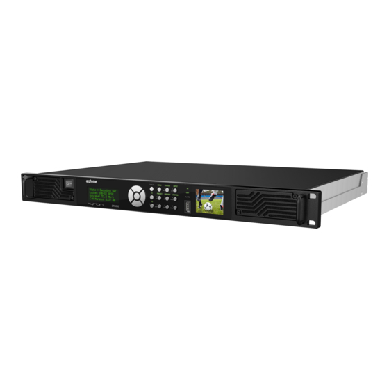
Page 12: Front View
Front Panel Interfaces FP are described in Section 4.2, “ Front Panel ” Ventilation using Air Intakes A is described in Section 2.4, “ Ventilation ” Note Depending on your hardware options, a double slot CAM input may also be present. www.ateme.com Page 12... -
Page 13: Rear View
RJ-45 connector, IP stream input/output (can be used for management as well). Audio Out BNC Connector for EBU/AES digital audio output. AC Inlet Connect the provided cable to the inlet. The decoder auto-detects the input AC voltage. Figure 2.3. Rear View Interface example 2 www.ateme.com Page 13... -
Page 14: Dvb-S2 Io Interfaces
These 4 connectors are internally mapped to a single tuner/de- PUTS 1-4 modulator. The input connector is choosen through the decoder configuration. RF Loop- This 75 Ohms, type F connector is a loopback of the choosen back RF INPUT connector, without any signal processing. www.ateme.com Page 14... -
Page 15: Asi Io Interfaces
These are two mirror connectors (they will always output the same SDI signal). This connector can be used either as a mirror of the SDI SDI OUT 2 OUT 1 connectors, or to output a different SDI signal. www.ateme.com Page 15... -
Page 16: Synchonization Io Interfaces
Figure 2.8. Stream Ethernet Interfaces Table 2.8. Stream Ethernet Interfaces Description This RJ45 connector holds a gigabit ethernet link, that can Stream 1-2 be used both for receiving and streaming Transport Stream. www.ateme.com Page 16... -
Page 17: Ethernet Management Interface
The Kyrion(R) DR5000 may have an optional analog audio extension board. This provides four independent analog balanced audio outputs, under the form of Sub-D25 connector. The user can configure which audio track is provided on each analog output. www.ateme.com Page 17... -
Page 18: Analog Output Interfaces
DR5000 User Manual UM-DR5000-FW1.2.1.0-REV1.0 2015-02-13 Figure 2.11. Analog Output Interfaces Table 2.9. Analog audio extension board Sub-D25 connector mapping Pin Index Function AUDIO_OUT_P_8 AUDIO_OUT_N_7 AUDIO_OUT_P_6 AUDIO_OUT_N_5 AUDIO_OUT_P_4 AUDIO_OUT_N_3 AUDIO_OUT_P_2 AUDIO_OUT_N_1 AUDIO_OUT_N_8 AUDIO_OUT_P_7 AUDIO_OUT_N_6 AUDIO_OUT_P_5 AUDIO_OUT_N_4 AUDIO_OUT_P_3 AUDIO_OUT_N_2 AUDIO_OUT_P_1 www.ateme.com Page 18... -
Page 19: Ventilation
Place the Kyrion(R) in a well-ventilated space, and allow ideally up to 10cm of free space on all sides of the Kyrion(R) so increasing air circulation and cooling. Warning Never obstruct air intakes and outtakes. Beware of 19'' bays doors, if any. www.ateme.com Page 19... -
Page 20: Installation
Power up the decoder by connecting the power cable, and placing the power switch on 1. Both the LCD and the TXT front panel should instantaneously display welcome messages. After a few sec- onds, the decoded service found on the ASI input transport stream will be displayed on your monitor. www.ateme.com Page 20... -
Page 21: Quick Start
Web GUI by launching your favorite web browser, and entering the configured IP address in the browser address bar. The DR5000 GUI should be launched. Warning The DR5000 requires Adobe Flash Player, version 10 or above. www.ateme.com Page 21... -
Page 22: Accessing The Web Gui
DR5000 User Manual UM-DR5000-FW1.2.1.0-REV1.0 2015-02-13 Figure 3.1. Accessing the Web GUI www.ateme.com Page 22... -
Page 23: User Interfaces
The web interface provides access to all the parameters but need a network connection to be used. The Front Panel interface provides access to all the operational parameters and most of the system ones. Choose the most appropriate way depending on your overall system’s design. www.ateme.com Page 23... -
Page 24: Front Panel
Off: No Status ALARM Solid Red: Decoder alarm Note The events that will switch the "ALARM" LED to "Solid RED" can be configured in the Web GUI. 4.2.2. LCD The LCD [FP4] displays some status information and configuration menus. www.ateme.com Page 24... -
Page 25: Tft
Section 5.1, “ Overview ” Table 4.2. Front Panel Menu Bitrate Service Name/Id RTP/UDP Packet Size FEC Rows FEC Columns 1D/2D FEC Processed Packets IP Status Missing Packets Reordered Packets Corrected Packets Uncorrected Packets Duplicate Packets www.ateme.com Page 25... - Page 26 FEC Rate Roll Off Int. Frequency SAT Status Symbol Rate Power C/N Margin Pilots Format Manufacturer Serial Number Identifier Carrier ID Telephone Number Longitude Latitude User Information Size Profile Depth Video Color Space Output Bitrate Mode GrX/PrY www.ateme.com Page 26...
- Page 27 => Table 4.3, “Front Pan- uration el Configuration Menu” Clear Alarms Alarm List Mode Management Netmask Speed Mode Stream1 Netmask Network Speed Mode System Stream2 Netmask Speed Default Gateway Reset Routes Version Software Backup Factory Serial Number Hardware www.ateme.com Page 27...
-
Page 28: Front Panel Configuration Menu
Mpe (=> Table 4.7, “Front Panel Mpe Menu”) Table 4.4. Front Panel Input Menu Type Address Port Interface Buffer Size [ms] Enabled Mode Address[1-8] Enabled Address Port Failover Auto Join Mode Trig. Period [ms] Interface Enable VLAN VLAN Id www.ateme.com Page 28... -
Page 29: Front Panel Composition Menu
VLAN Id Table 4.5. Front Panel Composition Menu Primary Serv. Id Service Scndry Serv. Id Video Mode Silence Emulation Monitor Automatic Channel1 Channel Selection Audio EmbeddedAes[1-8] Channel2 Channel Selection PassThrough Aes Pair Sel. DolbyPassThrough Aes Pair Sel. www.ateme.com Page 29... - Page 30 Analog[1-4] Channel1 Channel Selection Channel Channel2 Selection Gain Descrambling Mode Mode Biss Biss-1 Key Biss-E Key Descrambling Force 3V3 Service limiting BR limit [mbps] Descr. Services Service[1-8] Service Id SMPTE 12M Selected Data Ancillary Selected SMPTE 2010 www.ateme.com Page 30...
- Page 31 Override Location Line Location SMPTE 334-1 Selected Source Override Location Line Location SMPTE 334-2 Selected Source Selected Teletext Source Selected CC 608 Source Selected Source SMPTE 2031 Selected Source Selected AMOL 48 Source Selected AMOL 96 Source www.ateme.com Page 31...
-
Page 32: Front Panel Output Menu
Selected AMOL 96 Source Selected Video Index Source Mode Source Overlay Teletext Page DVBS Serv. Index CC608 service Table 4.6. Front Panel Output Menu Full Pixel Range PsF Output Connector1 Mapping Connector2 Downscale Type Emulation Enabled Genlock www.ateme.com Page 32... -
Page 33: Front Panel Mpe Menu
Enabled Streams[1-3] Spoofing Src Ad- dress Enabled User- SSRC fined Value Enabled Columns Rows Step Remuxed Asi2 VPSC Enabled Descrambled Remux Bit. Modify Bitrate Table 4.7. Front Panel Mpe Menu Mpe Enabled Interface Enable VLAN VLAN Id www.ateme.com Page 33... -
Page 34: Web Gui
This panel is used to configure the DR5000, both from a system (IP Configura- address, SNMP management, Alarms reporting, etc.) and from a tion Panel configuration (input type, decoded service, etc.) point of view. re- fer to Section 4.3.3, “ Configuration Panel ” for more information. www.ateme.com Page 34... -
Page 35: Decoding Status Panels
Miscellaneous examples are shown on Section 4.3.2.1, “ Active service overview ” This panel reports the content of the trans- Probed programs port stream that has been discovered on www.ateme.com Page 35... -
Page 36: Active Service Overview
SDI (denoted GrX/pY for Group X, Pair Y) and for External AES (going from 1 to 4). Note The video bitrate may be incorrectly reported if it is wrongly reported at the elementary stream level; this bitrate is not computed, but read from the elementary stream. www.ateme.com Page 36... - Page 37 It is also the place where Carrier ID information may be reported, and where DVB-SSU packages can be monitored and downloaded. 4.3.2.2.1. Probed program list The name of the service will be displayed with the service ID when it is present. www.ateme.com Page 37...
-
Page 38: Probed Programs
"update_descriptor", the package may be automatically downloaded. One may also choose which package to down- load whan several packages have ben found. Please refer to Section 4.3.3.3.5.1, “ System actions ” for more infor- mation on managing DVB-SSU packages. www.ateme.com Page 38... -
Page 39: Input Status
An Advanced tab will be displayed, reporting the DVB-S/S2 signal characteris- DVB-S/S2 tics: C/N, C/N Margin, modulation type, FEC, roll-off, DVB-S2 pilots, BER and power. An additional graph displays evolution of C/N Margin over the last minute. Figure 4.6. Sat Input status example www.ateme.com Page 39... -
Page 40: Ip Input Status Example
• RTP: Duplicate Packet counter reports the number of IP frames that have been duplicated, based on RTP sequence number, for media packets only. • RTP: Out of order counter reports the number of IP frames that have been received, but not in the same order as they were sent. www.ateme.com Page 40... -
Page 41: Configuration Panel
(in such case, the associated input/output will be filled with solid red). Status Gives an overview of the DR5000 status, from a system point of view. Events will also be Panel logged in that window (please refer to Section 4.3.3.1.3, “ Message Log ” for more information) www.ateme.com Page 41... -
Page 42: Status Panel
Figure 4.8. Status Panel Table 4.12. Status Panel Description System Info Display high-level system information. Editable field that can be used as a 'sticky System Notes note' to remind that the unit is currently in use. www.ateme.com Page 42... - Page 43 “ Firmware And Troubleshooting ” for more information. Note Clearing the logs will not clear the opened alarms. Warning When clearing the logs, the latter will be deleted from the DR5000, not only from the Web GUI. This operation can not be canceled. www.ateme.com Page 43...
-
Page 44: Service Panel View
Section 5.1, “ Overview ”, while this section will focus on configuration (so-called "preset") management. Figure 4.9. Service Panel View Table 4.13. Service Panel Tabs Description Input Selects the input type (IP, ASI, DVB-S/S2) and its associated parameters. www.ateme.com Page 44... - Page 45 Note The configuration slots are stored permanently on the DR5000, they are of course persistent over system reboots. Note The edited configurations can be loaded in any of the DR5000 user interfaces (SNMP and Front Panel). www.ateme.com Page 45...
-
Page 46: System Panel Description
Define the events severity level, and the actions taken Alarm/Traps when the events occur. Also defines the SNMP trap targets. Allows to specify BISS injected IDs. Also provides access to BISS Id/CA DVB-CI MMI menus, if CAM extension board is available. www.ateme.com Page 46... -
Page 47: Network Panel
Use this page for upgrading your device to a new firmware, or when bleshooting required by the ATEME support, for troubleshooting your unit. 4.3.3.3.1. Setting Network And Time Use this tab to modify the IP settings for both streaming and management interfaces, and for setting the system time. - Page 48 • Route "interface" defines to which interface the route will apply; it should be noted that a route can pertain to all interfaces ("any"), and that "interface" refers to physical or virtual interfaces. www.ateme.com Page 48...
-
Page 49: Time Panel
Any modification of one of the four SNMP targets or of the SNMP community password will require a system reboot to be taken into account. Note The default SNMP passwords are "public" for the "read" community, and "private" for the "write" community. www.ateme.com Page 49... -
Page 50: Alarms And Traps Panel View
• Table 4.15, “Input alarms” includes all events concerning raw input module (ASI, IP, Sat and Zixi) low-level errors. • Table 4.16, “Stream alarms” includes all events concerning TS level. • Table 4.17, “Genlock alarms” includes all genlock-related events. www.ateme.com Page 50... -
Page 51: Input Alarms
Input bitrate is Higher than 72 Mbps Table C.8, “Specifica- Excessive CAM bitrate and cannot be forwarded to CAM. tion - Descrambling” Table 4.16. Stream alarms Alarm name Description Reference TS discontinuity on audio PID TS discontinuity found on audio PID www.ateme.com Page 51... -
Page 52: Genlock Alarms
No video output (either due to de- Section 5.3.2, “ Output activity missing coding error or missing input) Video Output ” Section 4.3.3.3.4.1, Missing license A missing licence is required for current configuration “ License handling ” www.ateme.com Page 52... -
Page 53: Configuration Alarms
TS discontinuity on audio PID (Refer to associated alarm description) TS discontinuity on video PID (Refer to associated alarm description) TS discontinuity on data PID (Refer to associated alarm description) TS discontinuity on other PID (Refer to associated alarm description) www.ateme.com Page 53... - Page 54 4.3.3.3.3. BISS/CA System Parameter This panel is meant to manage parameters that pertain to the descrambling, from a system point of view. It is used to manage BISS injected IDs, and to communicate with CAM modules through MMI mechanism. www.ateme.com Page 54...
-
Page 55: System Descrambling Parameters View
Figure 4.13, “System Descrambling Parameters view”. It should be noted that the CAM modules are responsible for the content of these panels. Note The "System" and "Biss Id/CA" menus will blink when a module requests an action from the end user. www.ateme.com Page 55... -
Page 56: Licenses View
The panel labeled 'A' of Figure 4.14, “Licenses view” is dedicated to license management. License state is reported in the panel labeled 'B', and license update can be performed through this page (license files must be provided exclusively by the support team) www.ateme.com Page 56... -
Page 57: Firmware And Troubleshooting View
The panel labeled 'A' of Figure 4.15, “Firmware and Troubleshooting view” is dedicated to firmware management. From here, you can, install a new firmware version, make a backup of your current version or restore your backup version. www.ateme.com Page 57... - Page 58 You can check that the upgrade process went well by checking that the displayed Current Version number is the expected one. Note Update package are specific files provided by ATEME support. They should bear the extension '.pkg'. Other files will be rejected. Firmware backup Click Backup, and press Yes in the popup asking you to confirm that you really want to save your current system version.
- Page 59 Note This feature is meant for IRD management in a global system. As such, it is highly recommended to contact the ATEME support team if using that feature is envisioned. Warning Depending on the "update_descriptor" located in the UNT, the DR5000 may automatically download and even install the update, which will of course interrupt the decoding process.
- Page 60 4.3.3.3.5.5. Troubleshooting Logs Upon request, you may be asked to retrieve 'debug package' that will be further analyzed by the ATEME technical support. This will be achieved by clicking the appropriate buttons (label 'E' of Figure 4.15, “Firmware and Trou- bleshooting view”).
- Page 61 DR5000 User Manual UM-DR5000-FW1.2.1.0-REV1.0 2015-02-13 Warning The recorded data may or may not be descrambled, depending on the IP forwarding output mode (refer to Section 5.7, “ Stream Forwarding ”) www.ateme.com Page 61...
-
Page 62: Setting Up A Configuration
The settings edited in the Web GUI are not sent to the DR5000 until the 'Apply' button has been clicked. If an edited parameter does the match the active parameter, it will be highlighted. Please refer to Sec- tion 4.3.3.2.1, “ Managing Multiple Configurations ” for more information on that topic. www.ateme.com Page 62... -
Page 63: Input
GUI location values Determines the DR5000 Label 'B' of Figure 5.1, ASI Connector 1, 2 ASI input connector “Input Type Parameter” 5.2.2. DVB-S/S2 Input DVB-S/S2 input requires to set up a few parameters before receiving a transport stream. www.ateme.com Page 63... -
Page 64: Dvb-S2 Settings View
“DVB-S2 Settings View” DVB-S2 Downlink frequency of the desired signal. Downlink The DR5000 will automatically derive the Label 'F' of Figure 5.2, Frequency intermediate frequency by comparing this “DVB-S2 Settings View” value to the Local Oscillator Frequency www.ateme.com Page 64... -
Page 65: Ip Input
It should be left to 0 if unused Warning LNB Control can damage your installation when enabled with improper infrastructure. Please contact ATEME support for more information. 5.2.2.1. Intermediate Frequency Derivation The DR5000 will automatically derive the intermediate frequency, based on both the Local Oscillator Frequency and the Downlink Frequency. -
Page 66: Ip Settings View
This buffer is responsible for IP dejitter- Input Label 'A' of Figure 5.3, Milliseconds ing and for FEC reconstruction. Large values Buffer Size “IP Settings View” implies more latency, but may enhance out- put signal stability and FEC reconstruction www.ateme.com Page 66... -
Page 67: Failover Ip Settings Description
“IP Settings View” time, but the DR5000 will receive both streams (increases the required bandwidth) Duration of inactivity after which a Label 'J' of Figure 5.3, Trigger Period milliseconds source will be considered as 'down' “IP Settings View” www.ateme.com Page 67... -
Page 68: Smpte 2022-7 Settings Description
Section 4.3.3.3.1, “ Set- Label 'L' of Figure 5.3, source In- A warning icon will appear when ting Network And Time ” “IP Settings View” terface trying to use a disabled interface for information on virtual interface configuration) www.ateme.com Page 68... -
Page 69: Ip Ssm Settings Description
• In 'include' mode, the DR5000 will subscribe to a multicast group, and request only sources that are part of the provided list. Note 'Excluding' no source is equivalent to including all the sources: it is the standard IGMP V2 behavior. Table 5.7. IP SSM Settings Description Possible Parameter Description GUI location values www.ateme.com Page 69... -
Page 70: Zixi Input
Note Version 1.2.1.0 of the DR5000 only support "push" mode, it can receive a stream coming from a ZIXI feeder or broadcaster, but can not "join" a stream with the "pull" method. www.ateme.com Page 70... -
Page 71: Zixi Settings View
Port “ZIXI Settings View” incoming ZIXI stream Note The appropriate ZIXI license must be installed on your system for this option to appear in the web GUI. Please contact the ATEME support team for more information. www.ateme.com Page 71... -
Page 72: Service Selection
This panel lets you choose which service (or which PIDs inside a service) you want to decode, and how the audio PIDs will be mapped on the available audio output pairs. Figure 5.5. Service Selection View That view is made of 3 panels that will be hereinafter described: Service Editor, Video Output, Audio Output. www.ateme.com Page 72... -
Page 73: Service Editor
'auto-service' mode, Label 'C' of Figure 5.5, Service Id Ser- if the Primary service Id was not found A val- “Service Selection View” vice Id ue of 0 means 'any' (fallback to 'auto' mode). www.ateme.com Page 73... -
Page 74: Video Output
“Service Selection View” Through, Disabled Pid (Auto, Selects the PID that will be output of Label 'F' of Figure 5.5, Monitor, a Pid the associated stereo pair. Only present “Service Selection View” Pass-through, in 'pid-locked' service selection mode www.ateme.com Page 74... - Page 75 Selecting a mode which is not compatible with a given PID will raise a configuration alarm, and no audio will be output on the associated pair. 5.3.3.1.1. Auto mode The DR5000 will automatically selects the appropriate processing and output of a given input PID, depending on its codec. www.ateme.com Page 75...
-
Page 76: Audio Mode Compliance
This is intended to correct misaligned DolbyE frames, by constantly tracking and correcting every incoming DolbyE frame. The default line (reported in Table 5.14, “DolbyE start line recommandations”) can be overriden to place the DolbyE data to any location in the SDI frame. www.ateme.com Page 76... -
Page 77: Analog Audio Output Levels Description
Table 5.15. Analog Audio Output Levels Description Output Level Description 24 dBu @ 0 dBFS USA standard, Dolby recommandations 22 dBu @ 0 dBFS France and Japan standards 18 dBu @ 0 dBFS EBU R68, most European countries www.ateme.com Page 77... -
Page 78: Audio Pid Selection Example 1
Group 2/Pair 1 auto 122 (AAC) Group 2/Pair 2 auto 123 (AAC) Group 3/Pair 1 auto none disabled Group 3/Pair 2 auto none disabled Group 4/Pair 1 auto none disabled Group 4/Pair 2 auto none disabled www.ateme.com Page 78... -
Page 79: Audio Pid Selection Example 2
PID 120 will Group 1/Pair 1 disabled disabled be skipped Group 1/Pair 2 auto 121 (S302M) pass-through PID 122 will Group 2/Pair 1 disabled disabled be skipped Group 2/Pair 2 auto 123 (AAC) Group 3/Pair 1 auto none disabled www.ateme.com Page 79... - Page 80 PID 120 will AES1 disabled disabled be skipped AES2 auto 121 (S302M) pass-through AES3 auto 122 (AAC) AES4 auto 123 (AAC) Pid-locked mode In Pid-Locked mode, the user is responsible for selecting the exact audio mapping. www.ateme.com Page 80...
-
Page 81: Biss/Ca
• All the programs will be descrambled. Selecting this mode can corrupt the forwarded stream if the input stream contains multiple programs scrambled with different keys. • Only the decoded program will be descrambled (the choice of the program being decoded is made in Section 5.3, “ Service Selection ”). www.ateme.com Page 81... -
Page 82: Biss Parameters
5.4.1, “ BISS parameters ” scrambling Parameters view” 12 (Biss 1) or 16 (Biss- SW or ESW key to be Label 'E' of Figure 5.6, “De- SW/ESW Key E1/2) hexa digits used for descrambling scrambling Parameters view” www.ateme.com Page 82... -
Page 83: Ca Parameters
The number of programs that the DR5000 will descramble will depend on the module capabilities. One should not try to descramble more programs than what is officially supported by the module vendor, otherwise unexpected behavior can occur. Note Parameters "Force3V3" and "Service limiting" have no effect in version 1.2.1.0 of the DR5000. www.ateme.com Page 83... -
Page 84: Data Output
This panel lets you choose which data (under the form of ANC/VBI) will be processed and output by the DR5000. Some data may also be "burnt" onto the video itself, for monitoring purposes. www.ateme.com Page 84... -
Page 85: Data Output View
DR5000 User Manual UM-DR5000-FW1.2.1.0-REV1.0 2015-02-13 Figure 5.7. Data Output View www.ateme.com Page 85... -
Page 86: Ancillary Data
Default Line (offset from the switch line) SMPTE 12 +2 (SD), N/A (HD) SMPTE 2010 SMPTE 2016 SMPTE 2031 SMPTE 334-1 SMPTE 334-2 SMPTE 2038 Table 5.22. Switch lines Video Format SMPTE RP168 Switch lines 625/50/i 6,319 525/59.94/i 10,273 1920x1080/X/i 7,569 1920x1080/X/p 1280x720/X/p www.ateme.com Page 86... - Page 87 SMPTE 2038 defines the carriage of arbitrary Ancillary Data Packets in an MPEG-2 Transport Stream. In the scope of the DR5000, SMPTE 2038 refers to the insertion of SMPTE 2038 messages directly into the SDI frame. As SMPTE www.ateme.com Page 87...
- Page 88 VBI data in HD, where VBI data do not exist "as-is". SMPTE 2031 can be seen as way of carrying, in the ancillary space, data that would have been modulated in the VBI space in SD format. www.ateme.com Page 88...
-
Page 89: Vbi Data
• Video Index (RP186): legacy way to carry Aspect Ratio and AFD BarData. The source can be a VBI PID (ETSI EN 301 775) or a video pid (through afd_data, carried in the user data of the video elementary stream) www.ateme.com Page 89... -
Page 90: Overlay
“Data Output View” Selects the CC service Label 'I' of Figure 5.7, CC service A service number (1-4) to be displayed “Data Output View” Note Version 1.2.1.0 can only be used to burn CC608. CC708 overlay is not supported. www.ateme.com Page 90... -
Page 91: Sdi Output
• In Auto-SDI, the output SDI format follows the video source. This is the most common use-case. • In SD-SDI, the output SDI format will always be SD-SDI, even though the input source may be HD. Selection between 625i (PAL) and 525i (NTSC) is made according to the source framerate. www.ateme.com Page 91... -
Page 92: Sdi Settings
(PCRs). When set to 'Genlock', the syn- ure 5.8, “Output niza- lock, VPSC chronization signal entered on the SYNC IN connector will parameters view” tion type be used as a source for the DR5000 output clock. When set to www.ateme.com Page 92... -
Page 93: Downscale Settings Description
Emulation pattern will be used as soon as the DR5000 fails to output a decoded picture. This is typically the case when the input signal is missing, or when a significant amount of errors prevent the video decoding process from decoding a valid picture. www.ateme.com Page 93... -
Page 94: Emulation Settings Description
5.6.2.5. Confidence Monitor "Confidence Monitor" is the front panel monitor. It can be disabled on a configuration basis, through checkbox "M" of Figure 5.8, “Output parameters view”. www.ateme.com Page 94... -
Page 95: Stream Forwarding
RF loopback, for instance) as descrambling and remuxing may be performed on the stream before being output. Figure 5.9. Stream Forwarding View 5.7.1. ASI Output ASI forwarding is performed through two (mirrored) ASI output connectors (refer Section 2.3.2, “ ASI IO Interfaces ”). www.ateme.com Page 95... -
Page 96: Ip Output
VPSC output will only be present when the appropriate license is installed on your system. Please contact the ATEME support team for more information on that topic. When VPSC license is missing, ASI2 output connector will be a mirror of ASI1 output connector. -
Page 97: Remux Output
5.7.3. Remux Output Stream remuxing allows to remove services payloads from the stream. Note The DR5000 leaves the SI/PSI tables unmodified. Precisely, PMT of removed services are not included in the stream, but are still referenced in the PAT. www.ateme.com Page 97... -
Page 98: Remux Output Parameter Description
“Stream Forwarding View” User-De- fined exclude When in User-Defined service selection mode, Label 'X' of Figure 5.9, Service list this list allows to specify all the programs “Stream Forwarding View” that are to be included/excluded from remux. www.ateme.com Page 98... -
Page 99: Mpe
Label 'B' of Figure 5.10, a pid shall be embedded following ETSI 301192. “MPE Settings View” Stream 1, Ethernet interface that will be used Label 'C' of Figure 5.10, Interface Stream 2 to output MPE-based datagrams “MPE Settings View” www.ateme.com Page 99... -
Page 100: Specific Operations
Note License files are specific files provided by ATEME support. They should bear the extension ".lic" and are bound to a specific unit Serial Number. If the file does not meet these requirements, it will be rejected. The lower section is a summary of the licensed features with their status: •... -
Page 101: Recovery
• Restore Factory: Restores the system to its factory version. It will reset everything including: services configuration settings, firmware version and system parameters. • This menu also displays one IP address configured on the system and current system version. www.ateme.com Page 101... -
Page 102: Mib User Guide
4 targets, on a user-specified port (although standard SNMP port 162 is recommended). All enabled traps are sent to all targets: enabled traps are configurable at the system level, not on a per-target basis. Traps are further detailed in Section A.3.5, “ Configuring communities and traps ”. www.ateme.com Page 102... - Page 103 Read-Only variables, "private" is associated to Read-Write variables. Those strings can be overriden. Please refer to Section 4.3.3.3.2, “ Setting Alarms And Traps ” and to Section A.3.5, “ Configuring communities and traps ” for more information. www.ateme.com Page 103...
-
Page 104: Mib Overview
For example, dr5000StatusInputBitrate leaf is located in dr5000StatusInput node, which is itself located in the dr5000Status node. Thanks to this naming convention, equivalences between Front Panel para- meters and SNMP nodes are easily found. www.ateme.com Page 104... -
Page 105: Main Nodes
Section A.3.8, “ Saving and loading a preset ”. • dr5000ChannelConfiguration (OID 1.3.6.1.4.1.27338.5.3.2) is used to modify the running configuration. For in- stance, this is the appropriate node for setting the input type, the decoded PIDs or the audio mapping. www.ateme.com Page 105... - Page 106 (OID 1.3.6.1.4.1.27338.5.8.2) is used to manage routes (specify a gateway for a given interface, for instance. This node is equivalent to Figure 4.10, “Network Panel” in the web GUI. Please refer to Section A.3.6, “ Configuring network interfaces ” and Section A.3.7, “ Configuring routes ” for more information. www.ateme.com Page 106...
- Page 107 Viewing/editing the content can be performed through node dr5000Channel (OID 1.3.6.1.4.1.27338.5.3), as explained in Section A.3.8, “ Saving and loading a preset ”. dr5000Licenses (OID 1.3.6.1.4.1.27338.5.13) List all the possible licenses and their state (present or not) on the unit. www.ateme.com Page 107...
-
Page 108: Mib Use Cases
Writing a protected node when the system is locked does not raise any warning: the effect is just not taken into account. The following example locks and unlocks the system. $ snmpset -v2c -c private host ATEME-DR5000-MIB::dr5000CommandSystemAction.0 i 2 ATEME-DR5000-MIB::dr5000CommandSystemAction.0 = INTEGER: lock(2) $ snmpset -v2c -c private host ATEME-DR5000-MIB::dr5000CommandSystemAction.0 i 3 ATEME-DR5000-MIB::dr5000CommandSystemAction.0 = INTEGER: unlock(3) -
Page 109: Setting Time
DR5000 User Manual UM-DR5000-FW1.2.1.0-REV1.0 2015-02-13 The following example performs a reboot. $ snmpset -v2c -c private host ATEME-DR5000-MIB::dr5000CommandSystemAction.0 i 1 ATEME-DR5000-MIB::dr5000CommandSystemAction.0 = INTEGER: reboot(1) A.3.4. Setting time The time on the DR5000 can be set in two ways: • Thanks to dr5000TimeDate. In such case, the value to set is the number of seconds since January 1st, 1970. -
Page 110: Configuring Network Interfaces
$ snmpset -v2c -c private host \ ATEME-DR5000-MIB::dr5000SnmpCommunityReadWrite.0 s "read/write" ATEME-DR5000-MIB::dr5000SnmpCommunityReadWrite.0 = STRING: read/write $ snmpset -v2c -c private host ATEME-DR5000-MIB::dr5000CommandSystemAction.0 i 1 ATEME-DR5000-MIB::dr5000CommandSystemAction.0 = INTEGER: reboot(1) The following example empties the list of trap target, and adds 172.16.1.22:1256 as a new target. -
Page 111: Configuring Routes
ATEME-DR5000-MIB::dr5000NetworkConnectionCard.3 = INTEGER: 2 $ snmpset -v2c -c private host \ ATEME-DR5000-MIB::dr5000NetworkConnectionIsEnabled.3 i 1 ATEME-DR5000-MIB::dr5000NetworkConnectionIsEnabled.3 = INTEGER: true(1) $ snmpset -v2c -c private host ATEME-DR5000-MIB::dr5000NetworkConnectionIsDhcp.3 i 2 ATEME-DR5000-MIB::dr5000NetworkConnectionIsDhcp.3 = INTEGER: false(2) $ snmpset -v2c -c private host \ ATEME-DR5000-MIB::dr5000NetworkConnectionAddress.3 d 10.16.127.221 ATEME-DR5000-MIB::dr5000NetworkConnectionAddress.3 = Hex-STRING: 0A 10 7F DD... -
Page 112: Saving And Loading A Preset
DR5000 User Manual UM-DR5000-FW1.2.1.0-REV1.0 2015-02-13 $ snmpset -v2c -c private host ATEME-DR5000-MIB::dr5000NetworkRouteIsEnabled.1 i 1 ATEME-DR5000-MIB::dr5000NetworkRouteIsEnabled.1 = INTEGER: true(1) $ snmpset -v2c -c private host \ ATEME-DR5000-MIB::dr5000NetworkRouteAddress.1 d 172.16.127.219 ATEME-DR5000-MIB::dr5000NetworkRouteAddress.1 = Hex-STRING: AC 10 7F DB $ snmpset -v2c -c private host \ ATEME-DR5000-MIB::dr5000NetworkRouteNetmask.1 d 0.0.0.0... -
Page 113: Asi Input
ATEME-DR5000-MIB::dr5000PresetPresetName.42 = STRING: MyConfiguration $ snmpset -v2c -c private host \ ATEME-DR5000-MIB::dr5000ChannelCommandLoadPreset.0 i 42 ATEME-DR5000-MIB::dr5000ChannelCommandLoadPreset.0 = INTEGER: 42 $ snmpset -v2c -c private host ATEME-DR5000-MIB::dr5000ChannelCommandAction.0 i 2 ATEME-DR5000-MIB::dr5000ChannelCommandAction.0 = INTEGER: load(2) $ snmpset -v2c -c private host \ ATEME-DR5000-MIB::dr5000ChannelCommandSavePreset.0 i 51 ATEME-DR5000-MIB::dr5000ChannelCommandSavePreset.0 = INTEGER: 51... -
Page 114: Ip Input With Fec
ATEME-DR5000-MIB::dr5000ChannelConfigurationInputIpInterface.0 i 1 ATEME-DR5000-MIB::dr5000ChannelConfigurationInputIpInterface.0 = INTEGER: stream1(1) $ snmpget -v2c -c private host ATEME-DR5000-MIB::dr5000StatusInputTsLocked.0 ATEME-DR5000-MIB::dr5000StatusInputTsLocked.0 = INTEGER: true(1) $ snmpset -v2c -c private host ATEME-DR5000-MIB::dr5000CommandInputAction.0 i 1 ATEME-DR5000-MIB::dr5000CommandInputAction.0 = INTEGER: resetStats(1) $ snmpget -v2c -c private host ATEME-DR5000-MIB::dr5000StatusInputIpIsRtp.0 ATEME-DR5000-MIB::dr5000StatusInputIpIsRtp.0 = INTEGER: true(1) $ snmpget -v2c -c private host ATEME-DR5000-MIB::dr5000StatusInputIpPacketSize.0... -
Page 115: Ip Input With Failover
2015-02-13 $ snmpset -v2c -c private host \ ATEME-DR5000-MIB::dr5000ChannelConfigurationInputIpIsFecEnabled.0 i 1 ATEME-DR5000-MIB::dr5000ChannelConfigurationInputIpIsFecEnabled.0 = INTEGER: true(1) $ snmpget -v2c -c private host ATEME-DR5000-MIB::dr5000StatusInputIpFecRows.0 ATEME-DR5000-MIB::dr5000StatusInputIpFecRows.0 = INTEGER: 4 $ snmpget -v2c -c private host ATEME-DR5000-MIB::dr5000StatusInputIpFecColumns.0 ATEME-DR5000-MIB::dr5000StatusInputIpFecColumns.0 = INTEGER: 3 $ snmpget -v2c -c private host ATEME-DR5000-MIB::dr5000StatusInputIpIs2dFec.0 ATEME-DR5000-MIB::dr5000StatusInputIpIs2dFec.0 = INTEGER: false(2) -
Page 116: Dvb-S/S2 Input
$ snmpget -v2c -c private host \ ATEME-DR5000-MIB::dr5000StatusInputIpFailoverSecondary.0 ATEME-DR5000-MIB::dr5000StatusInputIpFailoverSecondary.0 = INTEGER: inactive(2) $ snmpset -v2c -c private host ATEME-DR5000-MIB::dr5000CommandFailoverAction.0 i 2 ATEME-DR5000-MIB::dr5000CommandFailoverAction.0 = INTEGER: forceToggle(2) A.3.13. DVB-S/S2 Input To configure DVB-S/S2 input, one must first set the dr5000ChannelConfigurationInputType to sat(3). Then, the node dr5000ChannelConfigurationInputSat must be used to configure DVB-S/S2 specific parameters (frequency, etc.), and... - Page 117 2015-02-13 # Set Input to sat (3) $ snmpset -v2c -c private host \ ATEME-DR5000-MIB::dr5000ChannelConfigurationInputType.0 i 3 ATEME-DR5000-MIB::dr5000ChannelConfigurationInputType.0 = INTEGER: sat(3) # Set the input physical interface to rf3 (3) $ snmpset -v2c -c private host \ ATEME-DR5000-MIB::dr5000ChannelConfigurationInputSatInterface.0 i 3 ATEME-DR5000-MIB::dr5000ChannelConfigurationInputSatInterface.0 = INTEGER: rf3(3)
-
Page 118: Automatic Audio Composition
# Check the lock flag, and get the exact lock frequency and the C/N Margin ... $ snmpget -v2c -c public host \ ATEME-DR5000-MIB::dr5000StatusInputSatLocked.0 ATEME-DR5000-MIB::dr5000StatusInputSatLocked.0 = INTEGER: true(1) $ snmpget -v2c -c public host \ ATEME-DR5000-MIB::dr5000StatusInputSatFrequency.0 ATEME-DR5000-MIB::dr5000StatusInputSatFrequency.0 = INTEGER: 1667498 $ snmpget -v2c -c public host \ ATEME-DR5000-MIB::dr5000StatusInputSatSnrMargin.0... -
Page 119: Configuring Biss-E
ATEME-DR5000-MIB::dr5000ChannelConfigurationCompositionVideoPid.0 i 120 ATEME-DR5000-MIB::dr5000ChannelConfigurationCompositionVideoPid.0 = INTEGER: 120 $ snmpset -v2c -c private host\ ATEME-DR5000-MIB::dr5000ChannelConfigurationCompositionAudioEmbeddedAesMode.3 i 3 ATEME-DR5000-MIB::dr5000ChannelConfigurationCompositionAudioEmbeddedAesMode.3=\ INTEGER: passthrough(3) $ snmpset -v2c -c private host ATEME-DR5000-MIB::\ dr5000ChannelConfigurationCompositionAudioEmbeddedAesMonitorPid.3 i 132 ATEME-DR5000-MIB::dr5000ChannelConfigurationCompositionAudioEmbeddedAesMonitorPid.3=\ INTEGER: 132 $ snmpset -v2c -c private host\ ATEME-DR5000-MIB::dr5000ChannelConfigurationCompositionAudioExternalAesMode.2 i 5 ATEME-DR5000-MIB::dr5000ChannelConfigurationCompositionAudioExternalAesMode.2=\... -
Page 120: Clock Synchronization
INTEGER: bisse1(2) $ snmpset -v2c -c private host \ ATEME-DR5000-MIB::dr5000ChannelConfigurationCompositionDescramblingBissBissEKey.0\ s 1234567890abcdef ATEME-DR5000-MIB::dr5000ChannelConfigurationCompositionDescramblingBissBissEKey.0 = \ STRING: 1234567890abcdef $ snmpset -v2c -c private host \ ATEME-DR5000-MIB::dr5000BissKeyInjectedId.1 s aabbccddeeff00 ATEME-DR5000-MIB::dr5000BissKeyInjectedId.1 = STRING: aabbccddeeff00 Note scrambling state current program found dr5000StatusDecodeCurrentProgramScrambled. A.3.17. Clock synchronization To configure clock synchronization, the genlock must be activated in dr5000ChannelConfigurationOutputGenlock. -
Page 121: Ip Forwarding
Section 5.7.2, “ IP Output ”. The following example activates descrambled IP forwarding to stream1/225.127.221.1:1234 $ snmpset -v2c -c private host \ ATEME-DR5000-MIB::dr5000ChannelConfigurationOutputForwardIpIsDescrambled.0 i 2 ATEME-DR5000-MIB::dr5000ChannelConfigurationOutputForwardIpIsDescrambled.0 = \ INTEGER: false(2) $ snmpset -v2c -c private host \ ATEME-DR5000-MIB::dr5000ChannelConfigurationOutputForwardIpIsRemuxed.0 i 2... -
Page 122: Checking Composition Results
INTEGER: 13000000 $ snmpset -v2c -c private host \ ATEME-DR5000-MIB::dr5000ChannelConfigurationOutputForwardRemuxServiceMode.0 i 2 ATEME-DR5000-MIB::dr5000ChannelConfigurationOutputForwardRemuxServiceMode.0 = \ INTEGER: include(2) $ snmpset -v2c -c private host ATEME-DR5000-MIB::\ dr5000ChannelConfigurationOutputForwardRemuxServiceIdServiceId.1 i 42 ATEME-DR5000-MIB::dr5000ChannelConfigurationOutputForwardRemuxServiceIdServiceId.1 =\ INTEGER: 42 $ snmpset -v2c -c private host ATEME-DR5000-MIB::\ dr5000ChannelConfigurationOutputForwardRemuxServiceIdServiceId.2 i 51 ATEME-DR5000-MIB::dr5000ChannelConfigurationOutputForwardRemuxServiceIdServiceId.2 =\... -
Page 123: Ts Descriptor
DR5000 User Manual UM-DR5000-FW1.2.1.0-REV1.0 2015-02-13 $ snmpget -v2c -c private host ATEME-DR5000-MIB::dr5000StatusDecodeCurrentProgramId.0 ATEME-DR5000-MIB::dr5000StatusDecodeCurrentProgramId.0 = INTEGER: 1281 $ snmpget -v2c -c private host \ ATEME-DR5000-MIB::dr5000StatusDecodeCurrentProgramVideoConfigurationPid.0 ATEME-DR5000-MIB::dr5000StatusDecodeCurrentProgramVideoConfigurationPid.0 =\ INTEGER: 120 $ snmpget -v2c -c private host \ ATEME-DR5000-MIB::dr5000StatusDecodeCurrentProgramAudioConfigurationMode.9 ATEME-DR5000-MIB::dr5000StatusDecodeCurrentProgramAudioConfigurationMode.9 =\ INTEGER: decode(2) $ snmpget -v2c -c private host \ ATEME-DR5000-MIB::dr5000StatusDecodeCurrentProgramAudioConfigurationDecodedPid.9.1... - Page 124 (France 2 HD). # Check if the IRD is locked on a TS $ snmpget -v2c -c private host ATEME-DR5000-MIB::dr5000StatusInputTsLocked.0 ATEME-DR5000-MIB::dr5000StatusInputTsLocked.0 = INTEGER: true(1) $ snmpget -v2c -c private host ATEME-DR5000-MIB::dr5000StatusInputBitrate.0 ATEME-DR5000-MIB::dr5000StatusInputBitrate.0 = INTEGER: 24882...
- Page 125 2015-02-13 # List the stream of the decoded service $ snmpget -v2c -c private host \ ATEME-DR5000-MIB::dr5000StatusTsDescriptorProgramStreamCount.2 ATEME-DR5000-MIB::dr5000StatusTsDescriptorProgramStreamCount.2 = INTEGER: 9 $ snmpget -v2c -c private host \ ATEME-DR5000-MIB::dr5000StatusTsDescriptorProgramStreamPid.2.1 ATEME-DR5000-MIB::dr5000StatusTsDescriptorProgramStreamPid.2.1 = INTEGER: 220 $ snmpget -v2c -c private host \ ATEME-DR5000-MIB::dr5000StatusTsDescriptorProgramStreamType.2.1...
-
Page 126: Input Statistics
• Input status tab of Decodig Status Panel (See Section 4.3.2.3, “ Input status ”). • Firmware/Troubleshooting tab of System Panel (See Section 4.3.3.3.5.5, “ Troubleshooting ”). This file is a CSV file with semi-colon separated values. One line corresponds to one measure point. www.ateme.com Page 126... -
Page 127: Input Statistics File Format
Error rate after FEC correction [%] Jitter [ms] Table B.3. IP with Failover input statistics 1-based Meaning field index Time and Date (expressed as DD/MM/YYYY HH:MM:SS) Input Type: IP-Failover Bitrate [kbps] Protocol (UDP/RTP) FEC rows FEC columns www.ateme.com Page 127... -
Page 128: B.4. Ip With Smpte 2022-7 Input Statistics
Jitter [ms] Primary source activity (true/false) Secondary source activity (true/false) Offset of the secondar source compared to the primary source [ms] Number of packets taken from the primary source Number of packets taken from the secondary source www.ateme.com Page 128... -
Page 129: B.5. Sat Input Statistics
Out of Order packet counter Dropped packet counter Duplicate packet counter Overflow packet counter Round Trip Time [ms] Network jitter [ms] Network latency [ms] ARQ responses counter FEC packets counter ARQ-Recovered packet counter FEC-Recovered packet counter Unrecovered packet counter www.ateme.com Page 129... -
Page 130: B.7. Ds3 Input Statistics
DR5000 User Manual UM-DR5000-FW1.2.1.0-REV1.0 2015-02-13 FEC bitrate [bps] Table B.7. DS3 input statistics 1-based field index Meaning Time and Date (expressed as DD/MM/YYYY HH:MM:SS) Input Type: DS3 Bitrate [kbps] Alarm (true/false) TS Alarm (true/false) Random (true/false) www.ateme.com Page 130... -
Page 131: Appendix
Front panel with LCD/alphanumerical keypad/Direct access keys Following DVB-SSU ETSI 102006 USB for configuration import/export USB for stream recording Video monitoring on Front panel video display and on Web GUI Audio monitoring on Front panel video display and on Web GUI www.ateme.com Page 131... -
Page 132: Specification - Video Codec
Table C.7. Specification - Data Input/Output Function Type Standard Present Teletext PID ETSI 300472 Teletext transported in VBI PID ETSI 301775 VBI Input CC transported in VBI PID ETSI 301775 VPS transported in a VBI PID ETSI 301775 www.ateme.com Page 132... - Page 133 VITC SMPTE 12M-1 SCTE104 SMPTE2010 Close Caption CEA-608 SMPTE334-1 Close Caption CEA-708 SMPTE334-2 VPID SMPTE352M Data Output SMPTE2016 VANC SMPTE2038 VITC SMPTE 12M-2 OP-47 OP-47 DVB-Sub ETSI-300743 Data Overlay Close Caption CEA-608 Close Caption CEA-608 Teletext ETSI-300706 www.ateme.com Page 133...
-
Page 134: Specification - Descrambling
RF input level: -65 dBm to -25 dBm Roll-Off 5/10/15/20/25/35 % Gold Code Nominal input impedance: 75 ohm 75 ohms Image rejection: > 40 dB > 40dB Input Return Loss: > 9.5 dB > 9.5 dB Noise Figure: < 12 dB < 12 dB www.ateme.com Page 134... -
Page 135: Specification - Environmental Conditions
-20°C to +70°C / -4°F to +158°F Operating humidity 5% to 90% (non condensing) Cooling air flow from front side to rear side. Table C.14. Specification - Physical Parameters Mass storage uSD disk Weight 3.4 kg/7.5 lbs www.ateme.com Page 135... -
Page 136: Specification - Power Supply
ETS 300-019-2-5: 2002 (sample operational) Random vibrations IEC 60068-2-27: 2008 (sample operational) Mechanical shocks Table C.20. Specification - CE Marking Directive 2006/95/EC: 12 December 2006 Directive 2004/108/EC:15 December 2004 1999/5/EC: 9 March 1999 www.ateme.com Page 136... -
Page 137: C.21. Specification - Material Declaration
DR5000 User Manual UM-DR5000-FW1.2.1.0-REV1.0 2015-02-13 Table C.21. Specification - Material Declaration EU RoHS2 Directive WEEE Directive www.ateme.com Page 137... -
Page 138: Warranty
• The broken part is a non ATEME approved replacement part; • The tamper seal on the Kyrion® casing is broken. ATEME and its suppliers accept no liability for any loss of service during the use of this device, or for any of the problems caused as a result. -
Page 139: Normative Reference
- Specifications of the teletext syntax VBI cc608 CEA/EIA-608-D (625i/525i) VBI VITC IEC-60461 (625i/525i) VBI VPS ETS 300 231-1998 (625i) ITU-R BT.1119-2 and ETSI EN 300 294 VBI WSS (625i) / IEC 61880 Ed. 1.0 b:1998 (525i) VBI WST ITU-R BT.653-3 (625i) www.ateme.com Page 139... -
Page 140: Glossary
In the remaining gaps are B-Frames. With the next I-Frame a new GOP begins. Graphical User Interface. HDTV High Definition Television International Electrotechnical Committee Internet Protocol International Standards Organisation ITU-R International Telecommunications Union - Radiocommunications Study Groups ITU-T International Telecommunications Union - Telecommunications Standardisation Sector Management www.ateme.com Page 140... - Page 141 Serial Digital I/O SMPTE Society of Motion Picture and Television Engineers SNMP, a communication protocol between management stations (consoles, for example) and man- SNMP aged objects, (such as routers, gateways, and switches) makes use of MIBs. Components controlled www.ateme.com Page 141...
- Page 142 SNMP uses a specified set of commands and queries. An MIB should contain information on these commands and on the target objects (controllable entities or potential sources of status information) with a view to tuning the network transport to the current needs. Transport Stream www.ateme.com Page 142...
-
Page 143: Support And Ressources
Customer Service ATEME Customer Service provides assistance with product information, sales, registration, and other non-technical issues. To find out how to contact ATEME Customer Service, please visit http://www.ateme.com/ for your region or country and click Contact Us. www.ateme.com Page 143...
Need help?
Do you have a question about the Kyrion DR5000 and is the answer not in the manual?
Questions and answers