Table of Contents
Advertisement
Quick Links
Item#: RTCC-020
RADIANT Turn
coordinator
Specifications, Installation
and Operation Instructions for the
Belite RADIANT Turn Coordinator
LAST UPDATED: September 2016
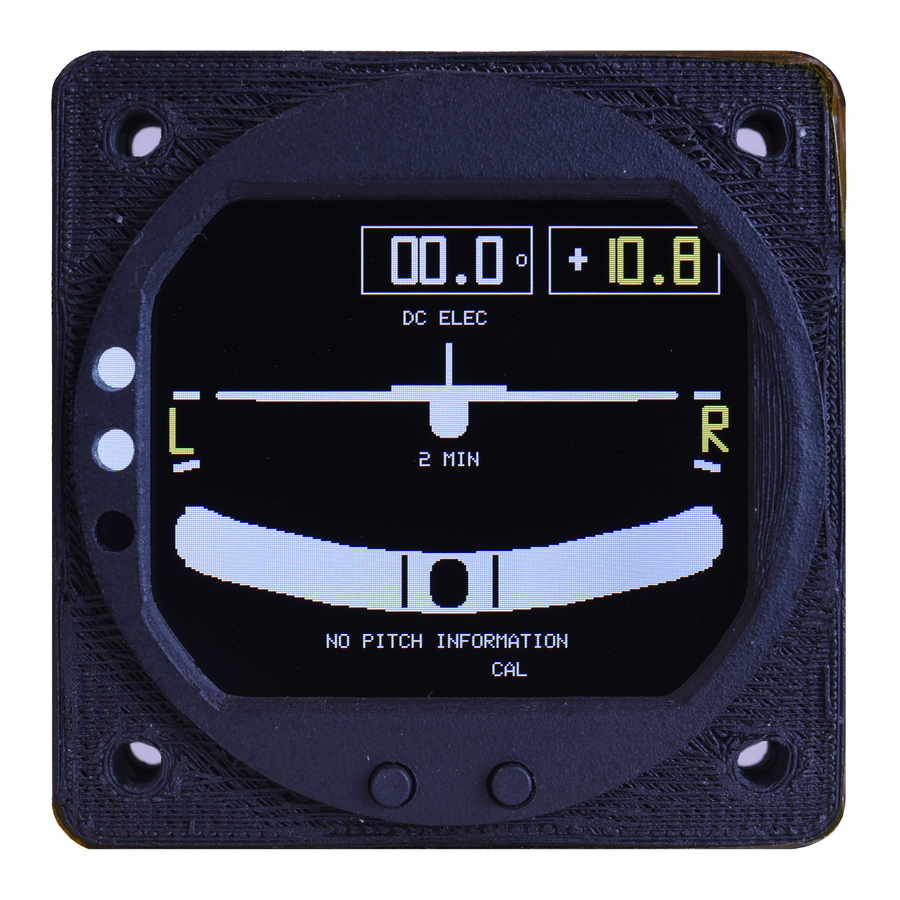
The Belite RADIANT RTCC is de-
signed to show simultaneous turn
(yaw) and bank (roll) information.
Yaw information is derived from a
solid state gyroscope. Roll informa-
tion is derived from a solid state
accelerometer.
All of this information is presented
digitally and graphically on a single
vivid LCD screen. The instrument fits
in a standard 2.25" enclosure.
This instrument will automatically
stabilize and provide the pilot with
information regardless of initial
position, acceleration, or attitude.
FEATURES
Brilliant daylight readable LCD
display
Provides current yaw in illustra-
tive (airplane) format, along with
degrees per second in digital
format.
Comes out of reset from any
flight attitude – gyroscope does
not lose reference lock.
Provides current roll via an illus-
trative bubble format.
Display is "sunglass friendly" --
bright; readable with polarized
glasses.
Works between -20C and +60C
SPECIFICATIONS
Weighs 1.6 ounces (50 grams)
Requires 10 to 36 volts < 100ma
@ full screen brightness. When
screen is dim, power consump-
tion of unit is approximately
15ma @ 28V.
BELITE ELECTRONICS is a Division of BELITE AIRCRAFT - Wichita, Kansas
Screen is non-polarized color LCD
display TFT Active Matrix with
resolution of 240 x 320 pixels
across a 2.4" display. Some corner
and side areas of the display
are not visible due to enclosure
requirements.
Unit operating temperature
between -20 and +60C, including
LCD screen.
Unit uses solid state gyroscope
and accelerometer.
Maximum turn rate for airplane
illustration is 5.0 degrees per
second.
Maximum turn rate for digital
yaw is > 10.0 degrees per second.
Dimensions for screen cutout are
shown below, see Figure 1.
Unit dimensions are 2.35" square
with a thickness of 0.75", not
including connector height.
Screen display mode is transmis-
sive, normally deep black. This
means that in the absence of
backlighting, you will not be able
to read the screen.
Screen contrast ratio is minimum
of 640.
Screen luminance is minimum of
450 cd/M2 at full brightness.
Screen viewing angle is up to 80
degrees.
Tactile switch input is provided
for calibration.
Voltage level information is
provided for ship power. Voltage
range is provided between 10
and 36 volts.
Two connectors are provided for
attaching power, probes, and
dimming input.
www.beliteaircraft.com
DISCLAIMER:
Products from Belite Electronics are not
designed to be used in applications where
their failure would endanger safe flight or
human life in any way. They are intended solely
for use in VFR conditions. They are not certified
to meet any Technical Standard Order, and are
not produced under a Parts Manufacturing
Authority (TSO / PMA). As a result, they are
suitable only for use in experimental and
ultralight aircraft, and in Light Sport Aircraft,
if meeting the requirements of the respective
manufacture.
WARRANTY:
Your new Belite Avionics instrument carries a
one year warranty. Please contact us at info@
beliteaircraft.com should your product need
warranty service. International warranty service
will be charged $50.00 US for repairs, which
includes return shipping after repair. Payment
must be received before service begins.
Ship to:
Belite Aircraft
8610 East 34th St. North #1
Wichita, KS 67226
RETURN/REFUND INFORMATION:
Must be returned in new, resalable condition
within 14 days
A New Generation of Digital Avionics
T: 316-253-6746
www.beliteaircraft.com
E: info@beliteaircraft.com
T: 316-253-6746
Advertisement
Table of Contents

Summary of Contents for Radiant RTCC-020
- Page 1 Specifications, Installation and Operation Instructions for the Belite RADIANT Turn Coordinator LAST UPDATED: September 2016 The Belite RADIANT RTCC is de- Screen is non-polarized color LCD signed to show simultaneous turn display TFT Active Matrix with (yaw) and bank (roll) information.
- Page 2 Radiant Turn coordinator page 2 SPECIFICATIONS CONT. FIVE PIN CONNECTOR: • GROUND, NC, NC, POWER INPUT, BACKLIGHT DIMMER SEVEN PIN CONNECTOR: • GROUND, NC, NC, +5V REGULATED POWER OUTPUT, DNC x 3 (DO NOT CONNECT x 3) • WARNING: DO NOT ATTACH ANY EXTERNAL POWER INPUT TO THE +5V OUTPUT on the seven pin connector. DOING SO WILL DAMAGE OR DESTROY YOUR UNIT. APPLICATIONS May be used to display turn rate and roll coordination information in experimental and ultralight aircraft; also in LSA aircraft with manufacturer approval.
- Page 3 Radiant Turn coordinator page 3 OPERATION Turn the unit on. A splash screen will display containing your model number and serial number. The screen will also show our company name, ‘Belite’ , along with the part number. If the display is dim, turn up the brightness using the included potentiometer.
Need help?
Do you have a question about the RTCC-020 and is the answer not in the manual?
Questions and answers