Table of Contents
Advertisement
Quick Links
S W A N C A M
QUAD ELEMENT PIR & MONO/COLOUR CAMERA MOTION DETECTOR With PET IMMUNITY
PRODUCT FEATURES
Video sensing device
• High sensitivity and high-resolution board
camera.
• Electronic shutter control.
Audio sensing device
• Omnidirectional response.
• High sensitivity.
•
AGC
• Quad (four element) PYRO sensor and hard
lens for outstanding detection performance and
elimination of false alarms.
• ASIC based electronics with movement speed
spectrum analysis.
• User-friendly installation with swivel bracket.
• BI directional temperature compensation.
• Environmental immunity.
• Pet immunity up to 25Kg. Pet active bellow 1m.
• Height installation calibrations free from 1.8m to
2.4m.
• Wide range operating voltage.
• High reliability and trouble free operation.
SELECT MOUNTING LOCATION
Choose a location most likely to intercept an intruder.
(Our recommendation is a corner installation). See
detection pattern fig.3. The quad-element high quality
sensor detects motion crossing the beam; it is slightly
less sensitive detecting motion toward the detector.
The SWAN CAM performs best when provided with a
constant and stable environment and background.
AVOID THE FOLLOWING LOCATIONS
• Facing direct sunlight.
• Facing areas that may change temperature
rapidly.
•
Areas where there are air ducts or substantial
airflows.
7101574_B
DETECTOR INSTALLATION
The detector can either be wall, corner or ceiling
mounted by using special bracket base for the bracket
mounting.
Refer to bracket description. (See fig. 6).
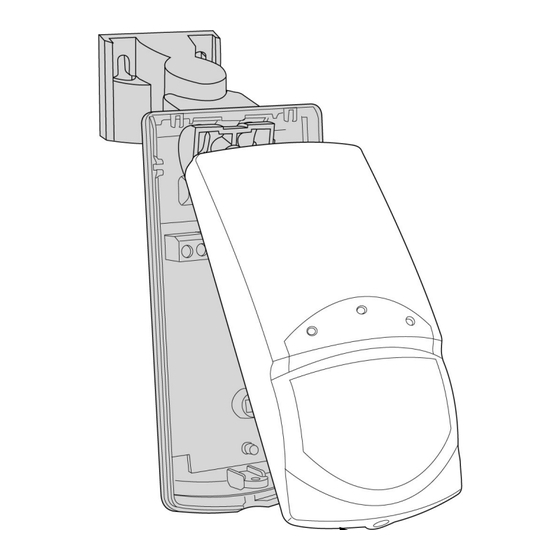
1. To remove the front cover, unscrew the holding screw
and gently raise the front cover. (See fig.2).
2. Insert wire through the bracket and holes "A" and
"B". (See fig.1)
3. Mount the bracket base to the wall or to the ceiling
with the suitable adaptor. Hold the detector base in
front of the protected area and tighten the bracket
screw.
4. Insert the wires through the bracket and connect the
wires to the terminal block.
5. Replace the cover by inserting it back in the
appropriate closing pins and screw in the holding
screw.
Unscrew the holding
screw and open base
Fig.1
Fig.3
- 1 -
DETECTOR CONNECTION
Terminal 1 - Marked " - " (GND)
Connect to the negative supply voltage output or ground
Terminal 2 - Marked " + " (+12V)
Connect to a positive supply voltage output of 8.2 -
16Vdc source (usually from the alarm control unit)
Terminals 3 & 4 - Marked " TAMP "
If a Tamper function is required connect these terminals
to a 24-hour normally closed protective zone in the
control unit. If the front cover of the detector is opened,
an immediate alarm signal will be sent to the control
unit.
Terminals 5,6 & 7 - Marked " N.C, C & N.O "
These are the output relay contacts of the detector.
Connect to a normally closed or normally opened zone
in the control panel.
Terminals 8 & 9 - Marked " AUD "& "GND"
This is the audio signal output. These two terminals
should be connected to an audio input.
Terminals 9 & 10 - Marked " GND "& "VID"
This is the video signal output. These two terminals
should be connected to video input.
TESTING THE DETECTOR
Wait one minute after applying 12Vdc power - warm up
time.
Conduct testing with the protected area cleared of all
people.
Walk test
Fig.2
NOTE:
Walk tests should be conducted, at least once a year, to
confirm proper operation and coverage of the detector.
INSTALLATION INSTRUCTIONS
1. Remove front cover.
2. Set LED to ON position.
3. Reassemble the front cover.
4. Start walking slowly across the detection zone.
5. Observe that the LED lights whenever motion is
detected.
6. Allow 5 sec. between each test for the detector to
stabilize.
7. After the walk test is completed, you can set the
LED to OFF position.
Fig.4
Advertisement
Table of Contents

Subscribe to Our Youtube Channel
Related Manuals for Crown SWAN CAM


Summary of Contents for Crown SWAN CAM
- Page 1 The SWAN CAM performs best when provided with a constant and stable environment and background. AVOID THE FOLLOWING LOCATIONS TESTING THE DETECTOR •...
- Page 2 INSTALLATION INSTRUCTIONS S W A N C A M QUAD ELEMENT PIR & MONO/COLOUR CAMERA MOTION DETECTOR With PET IMMUNITY N.O RELAY - TIME DELAY SETTING SETTING UP THE DETECTOR TECHNICAL SPECIFICATION Switches 4 & 5 of dipswitch DIP-5 use for setting the PET IMMUNITY SETTING Camera Type B&W:...
Need help?
Do you have a question about the SWAN CAM and is the answer not in the manual?
Questions and answers