Table of Contents
Advertisement
QQ
3 7 63 1515 0
Service
Manual
MULTI-CD/MD/DAB CONTROL DSP HIGH POWER CD PLAYER WITH RDS TUNER
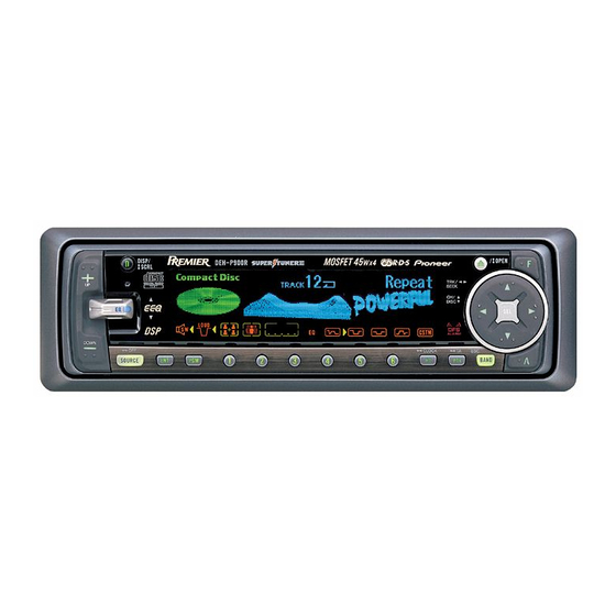
DEH-P9000R
- See the separate manual CX-916(CRT2300) for the CD mechanism description, disassembly and circuit
description.
- The CD mechanism employed in this model is one of S8 series.
TE
L 13942296513
CONTENTS
1. SAFETY INFORMATION ............................................2
2. EXPLODED VIEWS AND PARTS LIST .......................3
4. PCB CONNECTION DIAGRAM ................................32
www
5. ELECTRICAL PARTS LIST ........................................44
6. ADJUSTMENT..........................................................53
.
PIONEER ELECTRONIC CORPORATION
PIONEER ELECTRONICS SERVICE INC.
PIONEER ELECTRONIC [EUROPE] N.V.
PIONEER ELECTRONICS ASIACENTRE PTE.LTD. 253 Alexandra Road, #04-01, Singapore 159936
C PIONEER ELECTRONIC CORPORATION 1999
http://www.xiaoyu163.com
x
u163
P.O.Box 1760, Long Beach, CA 90801-1760 U.S.A.
Haven 1087 Keetberglaan 1, 9120 Melsele, Belgium
2 9
8
Q Q
3
6 7
1 3
1 5
7. GENERAL INFORMATION .......................................57
7.1 DIAGNOSIS ........................................................57
7.1.1 TEST MODE ..............................................57
7.1.2 DISASSEMBLY .........................................61
7.2 IC ........................................................................66
co
8. OPERATIONS AND SPECIFICATIONS.....................82
.
4-1, Meguro 1-Chome, Meguro-ku, Tokyo 153-8654, Japan
9 4
2 8
ORDER NO.
CRT2319
0 5
8
2 9
9 4
2 8
m
K-ZZB. APR. 1999 Printed in Japan
9 9
EW
9 9
Advertisement
Table of Contents

Related Manuals for Pioneer DEH-P9000R


Summary of Contents for Pioneer DEH-P9000R
-
Page 1: Table Of Contents
P.O.Box 1760, Long Beach, CA 90801-1760 U.S.A. PIONEER ELECTRONIC [EUROPE] N.V. Haven 1087 Keetberglaan 1, 9120 Melsele, Belgium PIONEER ELECTRONICS ASIACENTRE PTE.LTD. 253 Alexandra Road, #04-01, Singapore 159936 C PIONEER ELECTRONIC CORPORATION 1999 K-ZZB. APR. 1999 Printed in Japan http://www.xiaoyu163.com... -
Page 2: Safety Information
DEH-P9000R 3 7 63 1515 0 - CD Player Service Precautions 2. During disassembly, be sure to turn the power off 1. For pickup unit(CXX1285) handling, please refer since an internal IC might be destroyed when a con- to"Disassembly"(see page 61). -
Page 3: Exploded Views And Parts List
DEH-P9000R 3 7 63 1515 0 2. EXPLODED VIEWS AND PARTS LIST 2.1 PACKING L 13942296513 15 15 u163 http://www.xiaoyu163.com... -
Page 4: Http://Www.xiaoyu163.Com 3
DEH-P9000R 3 7 63 1515 0 NOTE: - Parts marked by “*” are generally unavailable because they are not in our Master Spare Parts List. ∇ mark on the product are used for disassembly. - Screws adjacent to - PACKING SECTION PARTS LIST Mark No. -
Page 5: Manual
DEH-P9000R 3 7 63 1515 0 2.2 EXTERIOR 3(1/2) L 13942296513 (2/2) u163 http://www.xiaoyu163.com... - Page 6 DEH-P9000R 3 7 63 1515 0 - EXTERIOR SECTION PARTS LIST Mark No. Description Part No. Mark No. Description Part No. 1 Screw BSZ26P060FMC 51 Heat Sink CNR1535 2 Screw BSZ30P050FMC 52 FM/AM Tuner Unit CWE1500 3 Cord CDE5536...
-
Page 7: Manual
DEH-P9000R 3 7 63 1515 0 Mark No. Description Part No. 101 Screw BSZ30P055FMC 102 Cord Assy CDE5845 103 Plug(CN4501) CKS-784 104 Case CNB2299 105 Case CNB2300 106 Detach Grille Assy CXB3271 107 Screw BPZ20P060FMC 108 Screw BPZ20P080FZK 109 Button(... - Page 8 DEH-P9000R 3 7 63 1515 0 2.3 CD MECHANISM MODULE L 13942296513 u163 http://www.xiaoyu163.com...
-
Page 9: Deh-P9000R 9
DEH-P9000R 3 7 63 1515 0 - CD MECHANISM MODULE SECTION PARTS LIST Mark No. Description Part No. Mark No. Description Part No. 1 Control Unit CWX2359 46 Sheet CNM6215 2 Connector(CN802) CKS2192 47 Ball CNR1189 3 Connector(CN801) CKS2193... -
Page 10: Block Diagram And Schematic Diagram
DEH-P9000R 3 7 63 1515 0 3. BLOCK DIAGRAM AND SCHEMATIC DIAGRAM 3.1 BLOCK DIAGRAM TUNER AMP UNIT ASL UNIT MIC4501 Q4501 VR4501 Q154 Q155 Q153 Q151 FM/AM TUNER UNIT FM/AM 1ST IF 10.7MHz FM FRONT END TMUTE FM MPX... -
Page 11: Manual
DEH-P9000R 3 7 63 1515 0 DSP UNIT ASL AMP ASL FILTER VR4501 CN141 X3101 IC 4501 IC 4502 NOISE BUFFER NJM2068 NJM2068 IC 3203(1/2) HD74HCT126FP CN252 CN3001 DOUT CN3001 CN252 SDIN IC 3301 SCKO BITCLK NJM4580M AOUTL1 LRCK... -
Page 12: Manual
DEH-P9000R 3.2 OVERALL CONNECTION DIAGRAM(GUIDE PAGE) 3 7 63 1515 0 Note: When ordering service parts, be sure to refer to “EXPLODED VIEWS AND PARTS LIST” or “ELECTRICAL PARTS LIST”. CD,TUNER,IP-BUS SIGNAL TUNER SIGNAL IP-BUS SIGNAL CD MECHANISM Large size... -
Page 13: Manual
DEH-P9000R 3 7 63 1515 0 TUNER AMP UNIT IP-BUS:+4.3dBs FM(100%):+1.6dBs AM(30%):-6.9dBs CN702 CN3001 PRE OUT E-VOL PRE OUT CD:+8.18dBs CD:+18.68dBs L 13942296513 RESET POWER AMP BACK SYSTEM CONTROLLER CEK1136 BACK UP 1K(1/2W) B REMOTE 1K(1/2W) BUZZER DOOR SW MUTE CD:+34.18dBs... -
Page 14: Manual
DEH-P9000R 3 7 63 1515 0 L 13942296513 u163 A-a G http://www.xiaoyu163.com... -
Page 15: Manual
DEH-P9000R 3 7 63 1515 0 L 13942296513 u163 A-a F http://www.xiaoyu163.com... -
Page 16: Manual
DEH-P9000R 3 7 63 1515 0 L 13942296513 u163 http://www.xiaoyu163.com... -
Page 17: Manual
DEH-P9000R 3 7 63 1515 0 L 13942296513 u163 http://www.xiaoyu163.com... -
Page 18: Manual
DEH-P9000R 3 7 63 1515 0 3.3 FM/AM TUNER UNIT Voltage of IC Terminals Mark Band Input Level None – – 0dBf 65dBf F125 125dBf 0dBµ 74dBµ A125 125dBµ L 13942296513 u163 http://www.xiaoyu163.com... -
Page 19: Manual
DEH-P9000R 3 7 63 1515 0 L 13942296513 u163 http://www.xiaoyu163.com... -
Page 20: Manual
DEH-P9000R 3 7 63 1515 0 3.4 KEYBOARD UNIT VOL+ DISP S1901,1902:CSG1113 S1903,1904:CSG1111 SOURCE VOL- S1905-1924:CSG1113 S1925:CSG1111 L 13942296513 AUDIO BAND EJECT FUNC u163 CN801 http://www.xiaoyu163.com... -
Page 21: Manual
DEH-P9000R 3 7 63 1515 0 KEYBOARD UNIT L 13942296513 u163 http://www.xiaoyu163.com... -
Page 22: Manual
DEH-P9000R 3 7 63 1515 0 3.5 DSP UNIT FREQUENCY CONVERSION BUFFER L 13942296513 DSP, DAC u163 http://www.xiaoyu163.com... -
Page 23: Manual
DEH-P9000R 3 7 63 1515 0 DSP UNIT CD,TUNER,IP-BUS SIGNAL TUNER SIGNAL IP-BUS SIGNAL CD(DIGITAL) SIGNAL CN252 L 13942296513 DSP CONTROLLER u163 http://www.xiaoyu163.com... -
Page 24: Manual
DEH-P9000R 3 7 63 1515 0 3.6 ASL UNIT ASL UNIT MICROPHONE L 13942296513 FILTER u163 http://www.xiaoyu163.com... -
Page 25: Manual
DEH-P9000R 3 7 63 1515 0 L 13942296513 u163 http://www.xiaoyu163.com... -
Page 26: Manual
DEH-P9000R 3.7 CD MECHANISM MODULE 3 7 63 1515 0 CONTROL UNIT PICKUP UNIT(SERVICE) RF-A CN101 L 13942296513 SWITCHES: CONTROL UNIT S801 : HOME SWITCH..ON-OFF S802 : CLAMP SWITCH..ON-OFF The underlined indicates the switch position. CD DRIVER PHOTO UNIT... -
Page 27: Manual
DEH-P9000R 3 7 63 1515 0 BIT LENGTH EXPANSION RF-AMP,SERVO,DSP,DAC CN702 L 13942296513 SINGLE-CD CONTROLLER u163 http://www.xiaoyu163.com... -
Page 28: Manual
DEH-P9000R 3 7 63 1515 0 Note:1. The encircled numbers denote measuring pointes in the circuit diagram. 2. Reference voltage REFO:2.5V - Waveforms 1 RFI 1 CH1: RFI 1 CH1: RFI 0.5V/div. 0.5µs/div. 1V/div. 1V/div. 0.5ms/div. 0.5ms/div. 2 CH2: MIRR... -
Page 29: Manual
DEH-P9000R 3 7 63 1515 0 8 CH1: TE 8 CH1: TE 0 MD 0.2V/div. 0.5V/div. 0.5V/div. 0.1s/div. 5ms/div. 20ms/div. 9 CH2: TD ! CH2: SD 0.2V/div. 0.5V/div. Normal mode: play TEST mode: 100 Tracks jump(FWD) Normal mode: Play (12cm) →... -
Page 30: Manual
DEH-P9000R 3 7 63 1515 0 6 CH1: FE 8 CH1: TE 0.2V/div. 0.2V/div. 1ms/div. 1ms/div. 3 CH2: FD 9 CH2: TD 0.5V/div. 0.5V/div. Normal mode: During AGC Normal mode: During AGC → → REFO REFO → REFO →... -
Page 31: Manual
DEH-P9000R 3 7 63 1515 0 L 13942296513 u163 http://www.xiaoyu163.com... -
Page 32: Pcb Connection Diagram
DEH-P9000R 4. PCB CONNECTION DIAGRAM CORD ASSY 3 7 63 1515 0 MAIN ANTENNA SUB ANTENNA 4.1 TUNER AMP UNIT NOTE FOR PCB DIAGRAMS 1. The parts mounted on this PCB include all necessary parts for several destination. For further information for... -
Page 33: Manual
DEH-P9000R 3 7 63 1515 0 SIDE A L 13942296513 u163 CN1901 http://www.xiaoyu163.com... -
Page 34: Manual
DEH-P9000R 3 7 63 1515 0 TUNER AMP UNIT L 13942296513 u163 http://www.xiaoyu163.com... -
Page 35: Manual
DEH-P9000R 3 7 63 1515 0 SIDE B L 13942296513 u163 http://www.xiaoyu163.com... -
Page 36: Manual
DEH-P9000R 3 7 63 1515 0 4.2 FM/AM TUNER UNIT SIDE A L 13942296513 u163 http://www.xiaoyu163.com... -
Page 37: Manual
DEH-P9000R 3 7 63 1515 0 SIDE B L 13942296513 u163 http://www.xiaoyu163.com... -
Page 38: Manual
DEH-P9000R 3 7 63 1515 0 4.3 KEYBOARD UNIT KEYBOARD UNIT KEYBOARD UNIT SIDE B SIDE A L 13942296513 u163 http://www.xiaoyu163.com... -
Page 39: Manual
DEH-P9000R 3 7 63 1515 0 4.4 DSP UNIT DSP UNIT SIDE A L 13942296513 DSP UNIT SIDE B u163 http://www.xiaoyu163.com... -
Page 40: Manual
DEH-P9000R 3 7 63 1515 0 4.5 ASL UNIT ASL UNIT CN141 SIDE A L 13942296513 ASL UNIT SIDE B u163 http://www.xiaoyu163.com... -
Page 41: Manual
DEH-P9000R 3 7 63 1515 0 4.6 SWITCH PCB SWITCH PCB BLUE WHITE CN851 4.7 MIC JACK PCB L 13942296513 MIC JACK PCB CN131 u163 http://www.xiaoyu163.com... -
Page 42: Manual
DEH-P9000R 3 7 63 1515 0 4.8 CD MECHANISM MODULE SIDE A L 13942296513 u163 http://www.xiaoyu163.com... -
Page 43: Manual
DEH-P9000R 3 7 63 1515 0 SIDE B L 13942296513 u163 http://www.xiaoyu163.com... -
Page 44: Electrical Parts List
DEH-P9000R 3 7 63 1515 0 5. ELECTRICAL PARTS LIST NOTES: - Parts whose parts numbers are omitted are subject to being not supplied. - The part numbers shown below indicate chip components. Chip Resistor RS1/_S___J,RS1/__S___J Chip Capacitor (except for CQS..) CKS.., CCS.., CSZS.. -
Page 45: Manual
DEH-P9000R 3 7 63 1515 0 =====Circuit Symbol and No.===Part Name Part No. =====Circuit Symbol and No.===Part Name Part No. ------ ------------------------------------------ ------------------------- ------ ------------------------------------------ ------------------------- Inductor LCTB4R7K2125 RS1/10S102J Inductor CTF1420 RS1/10S203J Inductor LCTA1R0J3225 RS1/10S0R0J Inductor CTF1295 RD1/4PU911J Inductor... -
Page 46: Manual
DEH-P9000R 3 7 63 1515 0 =====Circuit Symbol and No.===Part Name Part No. =====Circuit Symbol and No.===Part Name Part No. ------ ------------------------------------------ ------------------------- ------ ------------------------------------------ ------------------------- RS1/10S0R0J RS1/10S102J RS1/16S0R0J RS1/10S0R0J RS1/16S102J RS1/10S152J RS1/16S0R0J RS1/10S512J RS1/16S225J RS1/10S1R0J RS1/10S0R0J RS1/10S1R0J RS1/16S681J... -
Page 47: Manual
DEH-P9000R 3 7 63 1515 0 =====Circuit Symbol and No.===Part Name Part No. =====Circuit Symbol and No.===Part Name Part No. ------ ------------------------------------------ ------------------------- ------ ------------------------------------------ ------------------------- CKSYB105K16 CKSRYB472K50 CKSYB105K16 CKSQYB472K50 CKSYB105K16 CKSQYB103K50 CKSYB105K16 CEJA101M16 CKSQYB333K50 CKSQYB104K16 CKSQYB123K50 CCSQCH101J50 CKSQYB473K50... -
Page 48: Manual
DEH-P9000R 3 7 63 1515 0 =====Circuit Symbol and No.===Part Name Part No. =====Circuit Symbol and No.===Part Name Part No. ------ ------------------------------------------ ------------------------- ------ ------------------------------------------ ------------------------- Unit Number : CWE1500 RS1/16S433J Unit Name : FM/AM Tuner Unit RS1/16S562J RS1/16S333J... -
Page 49: Manual
DEH-P9000R 3 7 63 1515 0 =====Circuit Symbol and No.===Part Name Part No. =====Circuit Symbol and No.===Part Name Part No. ------ ------------------------------------------ ------------------------- ------ ------------------------------------------ ------------------------- CCSRCH151J50 Unit Number : CWM6225 CKSRYB473K16 Unit Name : Keyboard Unit CKSRYB682K25 CEAL2R2M50... -
Page 50: Manual
DEH-P9000R 3 7 63 1515 0 =====Circuit Symbol and No.===Part Name Part No. =====Circuit Symbol and No.===Part Name Part No. ------ ------------------------------------------ ------------------------- ------ ------------------------------------------ ------------------------- 1922 RS1/10S121J 3309 High Loss Inductor CTF1410 1923 RS1/10S2R2J 3310 High Loss Inductor... -
Page 51: Manual
DEH-P9000R 3 7 63 1515 0 =====Circuit Symbol and No.===Part Name Part No. =====Circuit Symbol and No.===Part Name Part No. ------ ------------------------------------------ ------------------------- ------ ------------------------------------------ ------------------------- 3202 CKSQYB474K16 Unit Number : 3203 CKSRYB103K50 Unit Name : Switch PCB 3204... -
Page 52: Manual
DEH-P9000R 3 7 63 1515 0 =====Circuit Symbol and No.===Part Name Part No. ------ ------------------------------------------ ------------------------- CAPACITORS CCSRCH102J25 CKSQYB104K16 CEV101M6R3 CEV470M6R3 CKSQYB334K16 CKSQYB334K16 CKSQYB334K16 CKSQYB104K16 CEV101M6R3 CKSQYB104K16 CKSRYB332K50 CKSQYB104K16 CKSRYB392K50 CKSQYB224K16 CCSRCH270J50 CCSRCJ3R0C50 CCSRCH221J50 CCSRCH101J50 CKSRYB682K25 CKSQYB104K16 CKSRYB104K16 CKSQYB104K16... -
Page 53: Adjustment
DEH-P9000R 3 7 63 1515 0 6. ADJUSTMENT 6.1 CD ADJUSTMENT 1) Precautions 2) Test Mode • This unit uses a single power supply (+5V) for the reg- This mode is used for adjusting the CD mechanism ulator. The signal reference potential, therefore, is module of the device. -
Page 54: Manual
DEH-P9000R 3 7 63 1515 0 - Flow Chart Test Mode In Reset SOURCE Sourse CD New test mode BAND Power ON (Adjustment for T.Offset) Power ON RF AMP Gain Select (Not adjustment for T.Offset) 00 00 00 Display... -
Page 55: Manual
DEH-P9000R 3 7 63 1515 0 6.2 CHECKING THE GRATING AFTER CHANGING THE PICKUP UNIT • Note : The grating angle of the PU unit cannot be adjusted after the PU unit is changed. The PU unit in the CD mecha- nism module is adjusted on the production line to match the CD mechanism module and is thus the best adjusted PU unit for the CD mechanism module. -
Page 56: Manual
DEH-P9000R 3 7 63 1515 0 Ech → Xch 20mV/div, AC Grating waveform Fch → Ych 20mV/div, AC 0° 30° 45° 60° L 13942296513 75° 90° u163 http://www.xiaoyu163.com... -
Page 57: General Information
DEH-P9000R 3 7 63 1515 0 7. GENERAL INFORMATION 7.1 DIAGNOSIS 7.1.1 TEST MODE - Error Messages If a CD is not operative or stopped during operation due to an error, the error mode is turned on and cause(s) of the error is indicated with a corresponding number. -
Page 58: Manual
DEH-P9000R 3 7 63 1515 0 - New Test Mode S-CD plays the same way as before. If an error such as off focus, spindle unlocking, unreadable sub-code, or sound skipping occurs after setup, its cause and time occurred (in absolute time) are displayed. -
Page 59: Manual
DEH-P9000R 3 7 63 1515 0 (4) Display of Operational Status (CPOINT) during Setup Status No. Contents Protective action CD+5V ON process in progress. None Servo LSI initialization (1/3) in progress. None Servo LSI CRAM initialization in progress. None Servo LSI initialization (2/3) in progress. -
Page 60: Manual
DEH-P9000R 3 7 63 1515 0 (5) Display Examples 1) During Setup (When status no. = 11) TRK No. MIN. SEC. 11" 2) During Operation (TOC read, TRK search, Play, FF and REV) The same as in the normal mode. -
Page 61: Disassembly
DEH-P9000R 3 7 63 1515 0 7.1.2 DISASSEMBLY 7.1.2 DISASSEMBLY CD Mechanism Module - Remove the Case (Not shown) 1. Remove the two screws, and then remove the Case. - Remove the CD Mechanism Module 1. Remove the four screws A. - Page 62 DEH-P9000R 3 7 63 1515 0 - Remove the Tuner Amp Unit (2/2) Antenna Cable 1. Remove the screw A, four screws C, and then remove the Antenna Cable and Holder. 2. Remove the screw B. 3. Stretch the four tabs, and then remove the Tuner Amp Unit.
-
Page 63: Manual
DEH-P9000R 3 7 63 1515 0 - Removing the Upper Frame 1. Remove six Springs A, two Springs B and four Upper Frame Screws. 2. Remove two Tabs situated on rear side of the Upper Frame, remove two Arms on the front side, then remove two Tabs on the front side. -
Page 64: Manual
DEH-P9000R 3 7 63 1515 0 - Removing the Guide Arm Assy 1. Remove a connector, a spring A and B Guide Arm Assy Section 2. Drive the Guide Arm Assy up aslant into rear side direction, then remove it from a Pin. Finally, drive the assembly approximately 45 degrees upward, then slide the assembly toward left side to remove it. -
Page 65: Manual
DEH-P9000R 3 7 63 1515 0 - Removing the Loading Motor and Carriage Motor 1. Remove the Spring and two Screws A. Guide 2. Dismount the Loading Motor. 3. Remove the Belt, a Screw B, two Screws C, a Guide... -
Page 66: Manual
DEH-P9000R 3 7 63 1515 0 7.2 IC PML004AF PD5482A PD5504A NJM4580M PA2028A BA6288FS AK7714 UPD63710GC PAL005A BR9010FV TC74HC393AF BA5985FM S-81250SGUP PD5471A TC9246F PD0236AM PM4009A PD8051A HD74HCT126FP PE5011C PML004AF L 13942296513 u163 http://www.xiaoyu163.com... -
Page 67: Manual
DEH-P9000R 3 7 63 1515 0 PA2028A PAL005A P-GND2 OUT2- STBY OUT2+ OUT1- P-GND1 OUT1+ S-GND Ac_gnd OUT3+ P-GND3 OUT3- L 13942296513 OUT4+ MUTE OUT4- S-81250SGUP P-GND4 Switch_out u163 http://www.xiaoyu163.com... -
Page 68: Manual
DEH-P9000R 3 7 63 1515 0 PM4009A L 13942296513 - Pin Functions (PD5482A) Pin No. Pin Name Function and Operation TUNPDO PLL data output TUNPCK PLL clock output TUNPCE PLL chip enable output TUNPCE2 PLL chip enable output 2... -
Page 69: Manual
DEH-P9000R 3 7 63 1515 0 Pin No. Pin Name Function and Operation P-BUS communication data output P-BUS communication data input BSCK P-BUS serial clock input/output FLPOPN Flap motor open output DPDT Display serial data output KYDT Display enable data input... -
Page 70: Manual
DEH-P9000R 3 7 63 1515 0 *PD5482A IC's marked by* are MOS type. Be careful in handling them because they are very liable to be damaged by electrostatic induction. BA6288FS DRIVER L 13942296513 CONTROL LOGIC POWER SAVE DRIVER BR9010FV... -
Page 71: Manual
DEH-P9000R 3 7 63 1515 0 - Pin Functions (PD5471A) Pin No. Pin Name Format Function and Operation 1–4 Not used Remote control reception BYTE External data BUS width select input CNVSS Processor mode select input Not used reset... -
Page 72: Manual
DEH-P9000R 3 7 63 1515 0 PD8051A A0-A19 :Address input D0-D15 :Data output byte :8/16 bit mode select :Chip enable input :Output enable input :Power supply :GND byte D15/A1 L 13942296513 *PD5504A u163 http://www.xiaoyu163.com... -
Page 73: Manual
DEH-P9000R 3 7 63 1515 0 - Pin Functions (PD5504A) Pin No. Pin Name Format Function and Operation VSS joint Not used Electronic volume strobe output Electronic volume data output Electronic volume clock output CNVSS VSS joint MCKRQ CD unit MCK request input... -
Page 74: Manual
DEH-P9000R 3 7 63 1515 0 - Pin Functions (AK7714) Pin No. Pin Name Function and Operation Not used 3–6 TEST Test terminal 1-4 Power supply (5v) Not used DVDD Digital VDD (5V) 10,11 DVSS Digital GND (0V) SDINA... -
Page 75: Manual
DEH-P9000R 3 7 63 1515 0 Pin No. Pin Name Function and Operation AOUTL2 DAC2 Lch analog output 75,76 Not used AOUTR1 DAC1 Rch analog output AOUTL1 DAC1 Lch analog output Not used Power supply (5V) Not used VRDAL... -
Page 76: Manual
DEH-P9000R 3 7 63 1515 0 TC74HC393AF TC9246F LOCK 1CLR 2CLR VDDA AMPI AMPO VSSA Selector L 13942296513 HD74HCT126FP NJM4580M A OUT A-IN B OUT B-IN- A+IN B+IN u163 http://www.xiaoyu163.com... -
Page 77: Manual
DEH-P9000R 3 7 63 1515 0 - Pin Functions (UPD63710GC) Pin No. Pin Name Function and Operation Logic circuit GND HOLD Defect detection output MIRR MIRR output RFOK signal output Reset signal input Command/parameter identification signal input Data strobe signal input... -
Page 78: Manual
DEH-P9000R 3 7 63 1515 0 Pin No. Pin Name Function and Operation ATEST Test pin RFMODE Use/not use select for internal RF amplifier A.GND Analog circuit GND Focus drive output Tracking drive output Sled drive output Spindle drive output... -
Page 79: Manual
DEH-P9000R 3 7 63 1515 0 - Pin Functions (BA5985FM) Pin No. Pin Name Function and Operation Loading driver FWD input OPIN1(+) CH1 pre-amplifier input OPIN1(−) CH1 pre-amplifier inverted input OPOUT1 CH1 pre-amplifier output OPIN2(+) CH2 pre-amplifier input OPIN2(−) -
Page 80: Manual
DEH-P9000R 3 7 63 1515 0 - Pin Functions(PE5011C) Pin No. Pin Name Format Function and Operation EJTSNS Disc eject position sense input DSCSNS Disc insert position sense input VDSENS VD power supply short sense input TEMP Temperature sense input... -
Page 81: Manual
DEH-P9000R 3 7 63 1515 0 Pin No. Pin Name Format Function and Operation tsck CD-TEXT serial clock output CD-TEXT serial data output CD-TEXT serial data input AVSS A/D GND *PE5011C L 13942296513 u163 http://www.xiaoyu163.com... -
Page 82: Operations And Specifications
DEH-P9000R 8. OPERATIONS AND SPECIFICATIONS 3 7 63 1515 0 - Connection Diagram L 13942296513 u163 http://www.xiaoyu163.com... -
Page 83: Manual
DEH-P9000R 3 7 63 1515 0 8.1 OPERATIONS DISPLAY button FUNCTION button EJECT button 5/∞/2/3 buttons RESET button ENTERTAINMENT button EQ button BAND button Buttons 1–6 +/– button PGM button PTY button TA button AUDIO button SOURCE/OFF button L 13942296513... -
Page 84: Manual
DEH-P9000R 3 7 63 1515 0 L 13942296513 u163 http://www.xiaoyu163.com... -
Page 85: Manual
DEH-P9000R 3 7 63 1515 0 L 13942296513 u163 http://www.xiaoyu163.com... -
Page 86: Manual
DEH-P9000R 3 7 63 1515 0 L 13942296513 u163 http://www.xiaoyu163.com... -
Page 87: Manual
DEH-P9000R 3 7 63 1515 0 8.2 SPECIFICATIONS Specifications General CD player Power source ..14.4 V DC (10.8 – 15.1 V allowable) System ........Compact disc audio system Grounding system ........Negative type Usable discs ..........Compact disc Max.