
Summary of Contents for Jean Lebeniste MC1100B
- Page 1 MODEL MC1100B VARIABLE SPEED WOOD LATHE INSTRUCTION MANUAL Please read and fully understand the instructions in this manual before operation. Keep this manual safe for future reference. Version: 2015.02.02...
-
Page 2: Technical Data
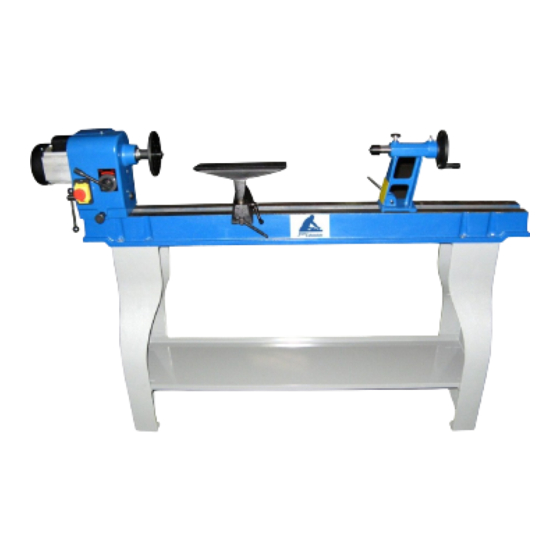
TECHNICAL DATA Model number………………………………………………...………………………………………………… MC1100B Speeds………………………………………………...…………………………..…………………………500-2000RPM Distance between centers ………………………………………………….….…..………………. 1100mm(43in.) Swing over bed………………………………………………………………………….…………………408mm(16in.) Drive spindle through hole……………….……………………………….…………………………..…………10mm Tailstock spindle through hole……………………………………………..……………………………………10mm Tailstock spindle travel….…………………………………………………………………….……………………54mm Headstock spur…………..………………………………………………………………spur center-Morse#2Taper Tailstock center………..………………………………………………………Ball bearing center-Morse#2Taper Net weight…………………………………………………….…………………………………………………….…132kgs GENERAL SAFETY RULES WARNING! WHEN USING ELECTRIC TOOLS BASIC SAFETY PRECAUTIONS SHOULD ALWAYS BE FOLLOWED TO REDUCE THE RISK OF FIRE,... - Page 3 Use safety glasses. Use face or dust mask if cutting operations create dust. 10. Connect dust extraction equipment If devices are provided for the connection of dust extraction and collecting equipment, ensure these are connected and properly used. 11. Do not abuse the cord Never yank the cord to disconnect it from the socket.
-
Page 4: Electrical Information
Specific safety rules for the wood lathe WARNING ! Do not operate your wood lathe until it is completely assembled and installed according to the instructions. 1. For your own safety, read the entire instruction manual before operating the lathe. 2. - Page 5 Extension cord sizes shown assure a voltage drop of not more than 5% at rated load of tool. Ampere rating (on name plate) Extension cord length Wire size mm² 7.5m 0.75 0.75 1.25 0.75 0.75 22.5m 0.75 0.75 0.75 0.75 1.25 0.75 1.25...
- Page 6 1. Lathe bed assembly 2. Face plate 3. Headstock spur center 4. Tailstock cup center 5. Push rod 6. Flat wrenches 7. Hex key 8. Instruction panel 9. Hex bolt 10. Front leg & rear leg Assembly Setting the lathe on the leg set (Fig 3) 1.
- Page 7 Spurs 1. Remove the faceplate [1] from the headstock spindle using the two wrenches provided [2] to separate the faceplate from the spindle nut. (Fig5) 2. Insert the headstock spur [3] in the spindle hole. 3. Insert the live center [4] in the tailstock hole.
-
Page 8: Operation
Operation Switch (Fig 9) The lathe is fitted with a no-volt switch. In the event of a power supply failure the wood lathe needs to be manually re-started by pushing the “I” button on the switch. Speed control (Fig 10) 1. -
Page 9: Maintenance
Tool rest (Fig 13) 1. The tool rest [1] can be used with or without the arm [2]. 2. To move the tool rest base [3], loosen the lock lever [4], and move the base to the right or left and back or front. -
Page 10: Parts List
PARTS LIST Part No Description Size Description Size Q’ty Part No Q’ty Screw M5X8 “C” ring Cover – motor Lever Hex screw M8X30 Handle M8x25 Washer Screw Motor M5x12 Pin-injection Screw “C'' ring Plate Screw M8x35 Motor Pulley Set, L&R Bolt “C”... -
Page 11: Parts Diagram
PARTS DIAGRAM: 10... -
Page 12: Wiring Diagram
WIRING DIAGRAM: 1.220-240V/50Hz, 1 Phase 2.380-400V/50Hz, 3 Phase 3. 110-120V/60Hz, 1 Phase 11...
Need help?
Do you have a question about the MC1100B and is the answer not in the manual?
Questions and answers