Advertisement
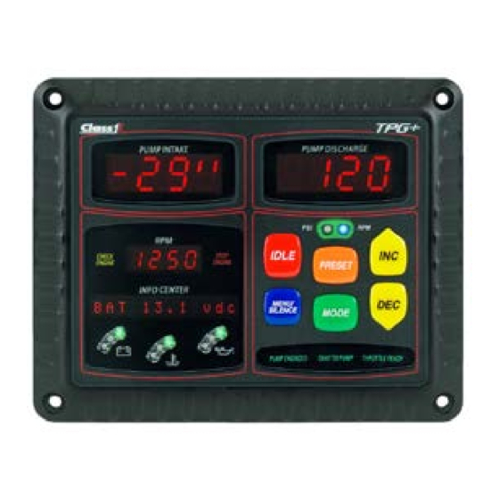
Total Pressure Governor Plus (TPG+)
OEM Quick Manual
INSTALLATION
Mount the TPG+ on the operator's panel with four #10 screws.
The dimensions in the detail below are in inches [millimeters].
DISCHARGE PRESSURE TRANSDUCER INSTALLATION
Install the 300 psi (2068 kPa, 20 bar) discharge pressure
transducer (p/n 113557) on the discharge side of the pump.
The pressure connection is a ¼-18 NPT male port. A 'T' fitting
can be used to share the pressure gauge outlet on the
discharge manifold.
INTAKE PRESSURE TRANSDUCER INSTALLATION
Install the 300 psi (2068 kPa, 20 bar) intake pressure
transducer (p/n 113557) on the intake side of the pump. The
pressure connection is a ¼-18 NPT male port.
VERIFY ENGINE RPM
Verify proper J1939 CAN connection to the engine's ECM by
monitoring the RPM display of the TPG+ while the engine is
running. The display should show accurate RPM information.
VERIFY INTERLOCKS
The TPG+ requires OEM provided interlocks THROTTLE READY and PUMP ENGAGED for proper operation. The TPG+ utilizes backlit text to
indicate interlock status. The interlock status indicators are located directly beneath the switch panel.
Activate the throttle ready interlock. (Apply system power to pin 2 of connector C4).
Verify the THROTTLE READY text illuminates.
► The TPG+ will operate in RPM mode only and cannot be changed to pressure mode.
Activate the pump engaged interlock. (Apply system power to pin 10 of connector C4).
Verify the PUMP ENGAGED text illuminates.
► The TPG+ will not operate in any mode without the THROTTLE READY interlock.
Activate the throttle ready and pump engaged interlocks. (Apply system power to pins 2
and 10 of connector C4).
Verify the PUMP ENGAGED, OKAY TO PUMP, and THROTTLE READY text
illuminates.
► The TPG+ will operate in either mode.
WIRING HARNESS
The main system harness (p/n 118453) is comprised of a pair of harnesses:
the power/communication harness (depicted below in blue) and the signals
harness (depicted below in green).
For the analog control option, add harness wires (p/n 118454) depicted in
red.
TPG+ OEM Quick Manual P/N 118712
REV A
05-16-2018
Advertisement
Table of Contents

Subscribe to Our Youtube Channel
Summary of Contents for Class 1 TPG+
- Page 1 TPG+ OEM Quick Manual P/N 118712 REV A 05-16-2018 Total Pressure Governor Plus (TPG+) OEM Quick Manual INSTALLATION WIRING HARNESS Mount the TPG+ on the operator’s panel with four #10 screws. The main system harness (p/n 118453) is comprised of a pair of harnesses: The dimensions in the detail below are in inches [millimeters].
- Page 2 For complete details please reference service bulletin SB-143 at www.haleproducts.com For detailed operation and troubleshooting consult the full manual (p/n 118711) available from the Class 1 web site www.Class1.com TPG+ OEM Quick Manual P/N 118712 REV A...
Need help?
Do you have a question about the TPG+ and is the answer not in the manual?
Questions and answers