Advertisement
Quick Links
FORM ASX-40020
INSTALLATION, OPERATING AND MAINTENANCE INSTRUCTIONS
Air Specialties Express, 448 S. Main St., P. O. Box 930040, Verona, WI 53593-0040
CAUTION!
MANUAL HAS BEEN READ AND UNDERSTOOD. READ AND SAVE THESE INSTRUCTIONS FOR FUTURE USE.
PRODUCT APPLICATION
SL-2000 Series duct smoke detectors provide early detection of
smoke and products of combustion present in air moving through
an HVAC duct supply, return, or both in commercial, industrial, and
residential applications. These devices are designed to prevent the
recirculation of smoke in areas by the air handling system's fans
and blowers. Complete systems may be shut down in the event of
smoke detection.
NOTE: For the correct installation of a duct smoke unit,
please refer to the NFPA 72 (National Fire Alarm Code), NFPA
90A (Standard for Installation of Air Conditioning and Ventilation
Systems),NFPA 92A (Recommended Practice for Smoke Control
Systems.), NFPA 5000 (Building Construction and Safety Code),
IMC (International Mechanical Code), and IFC (International Fire
Code).
This detector is not intended for open area protection nor should
it be used for early warning detection or replace a regular fire
detection system.
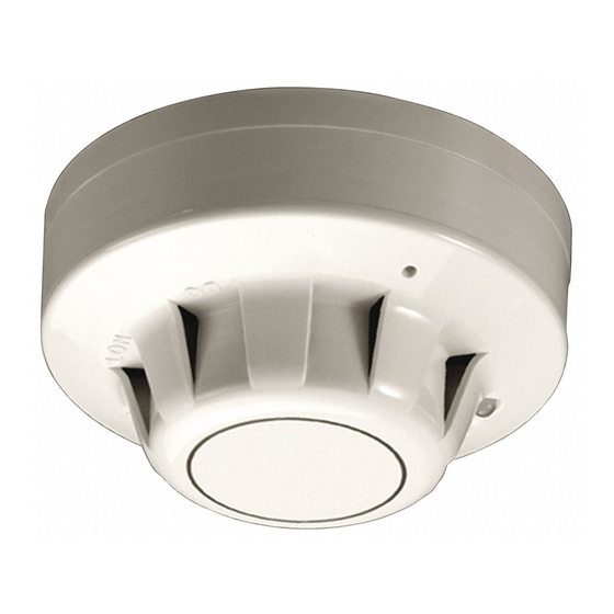
PRODUCT DESCRIPTION
The SL-2000 Series smoke detector is fitted with a mounting base
that will accept an ionization smoke detector head model 55000-
225APO or photoelectric smoke detector head model 55000-
328APO. The duct unit supports two sets of form "C" alarm con-
tacts, one form "A" alarm contact and one form "C" trouble contact.
The trouble contact supervises the presence of the input power,
removal of the detector cover and the removal of the smoke
detector head.
This detector is equipped with a cover removal switch
that instantly provides a trouble condition upon removal of
the clear cover. For all testing and inspection with the cover
removed, the cover removal switch (designated as SW1 on
PCB) must be manually depressed to simulate standard
"pilot" operation. THE TROUBLE CONTACTS (TERMINALS 4,
15, 5) ARE SHOWN IN THE NON-ENERGIZED CONDITION.
The trouble contacts will not operate in the event of a smoke alarm. The
SL-2000 Series duct detector will operate from various input voltage
sources; namely 24VAC, 24VDC, 115VAC and 230VAC.
SAMPLING TUBES
The operating principle of a duct detector is based on the Venturi
effect. Two tubes extend into the HVAC duct. Air flowing through
the duct is forced into the air intake (inlet) tube via the air intake
holes, (facing the air flow) and passes over the detector head. The
air will be drawn out via the exhaust tube back into the HVAC duct.
(A 7" exhaust tube is provided in the installation kit.) When the con-
centration of smoke particles suspended in the air stream reach
the alarm threshold of the detector head, the unit will go into alarm.
The duct smoke detector units are designed to operate in duct
widths from 6" to 10' wide with an air velocity between 100 to 4,000
feet per minute. To verify correct installation, the pressure
SL-2000 Series Smoke Detectors, Model EXSAA and EXSAB (Ionization),
DO NOT INSTALL, USE OR OPERATE THIS EQUIPMENT UNTIL THIS
PRODUCT OVERVIEW
EXSAG and EXSAH (Photoelectric)
Phone: (877)945-9175
differential between the sampling (high side) and exhaust (low
side) tubes should be measured using a Magnehelic pressure
gauge or equivalent. An acceptable reading is between 0.01 and
1.2 inches of water.
To minimize the impact of air turbulence and stratification on
performance, a duct smoke detector should be located as far as
possible downstream from any obstruction (i.e. deflector plates,
elbows, dampers, etc.). In all situations, confirmation of velocity
and pressure differential within specifications is required.
REMOTE ACCESSORIES
Audible and visual alarm indicators, remote status indicators, and
remote reset/test switches can be accommodated by the SL-2000
Series duct units by connecting to DC voltage output terminals as
described on Page 4. These terminals are not supervised and the
voltage/current will only be present when the detector unit is in
alarm. The remote pilot (green) LED will be permanently illuminat-
ed when connected to the output terminals as long as input power
and detector head are present.
SL-2000 AT-A-GLANCE
MODEL NUMBER:
SL-2000-N
4-Wire Ionization Duct Smoke Detector
SL-2000-P
4-Wire Photoelectric Duct Smoke Detector
DETECTOR HEAD MODEL NUMBER:
Ionization Detector Head:
Photoelectric Detector Head:
POWER REQUIREMENTS:
STANDBY CURRENT
24VAC
55 mA
24VDC
14 mA
115VAC
14 mA
230VAC
8 mA
RELAY CONTACT RATINGS:
Alarm contacts:
2 Sets form "C" rated at 10A @ 115VAC resistive
1 form "A" rated at 2A
Trouble contacts:
1 Set form "C" rated at 10A @ 115VAC resistive
Air velocity:
100 to 4,000ft./min.
Ambient temperature: SL-2000-N: 32°F to 158°F (0°C to 70°C)
SL-2000-P: 32°F to 140°F (0°C to 60°C)
Humidity:
10% to 85% RH Non-Condensing/Non-Freezing
Material:
Gray plastic back box with clear plastic cover
(Makrolon 94V-0)
Dimensions:
13½" L X 4½" W X 2¼" D
Max. net wt.:
3½ lbs.
Radioactive element: SL-2000-N (Ionization) - Americium 241,
0.9 micro curie.
Do not expose to corrosive atmospheres.
U.S. Patents 6,741,181 and Patents Pending
1
Fax: (608)845-6470
www.airspecialties.com
55000-225APO
55000-328APO
ALARM CURRENT
24VAC
190 mA
24VDC
115VAC
230VAC
68 mA
32 mA
18 mA
Advertisement

Related Manuals for Air Specialties Express SL-2000-N

Summary of Contents for Air Specialties Express SL-2000-N
- Page 1 FORM ASX-40020 INSTALLATION, OPERATING AND MAINTENANCE INSTRUCTIONS SL-2000 Series Smoke Detectors, Model EXSAA and EXSAB (Ionization), EXSAG and EXSAH (Photoelectric) Air Specialties Express, 448 S. Main St., P. O. Box 930040, Verona, WI 53593-0040 Phone: (877)945-9175 Fax: (608)845-6470 www.airspecialties.com CAUTION! DO NOT INSTALL, USE OR OPERATE THIS EQUIPMENT UNTIL THIS MANUAL HAS BEEN READ AND UNDERSTOOD.
-
Page 2: Mechanical Installation
MECHANICAL INSTALLATION LOCATION PREREQUISITES “NO-TOOLS” TUBE INSTALLATION This guideline contains general information on duct smoke The SL-2000 Series duct smoke detector provides a unique, detector installation, but does not preclude the NFPA and/or atent-pending mechanism for installation and/or removal of the ICC documents listed. -
Page 3: Electrical Installation
This duct smoke detector is shipped with a velocity adapter insert, either factory installed (SL-2000-P), or found in the installation kit (SL-2000-N). When installed, this adapter will allow the duct detector to operate at extremely low air velocities. To install the adapter, simply insert it into the slots provided inside the detector housing so that the adapter fits snugly over the smoke detector head. - Page 5 TESTING AND MAINTENANCE PROCEDURES OPERATIONAL TESTING SMOKE TESTING: Using smoke test canister with testing nozzle (available from Air Products and Controls Inc. part number TG- To determine the correct operation of the SL-2000 Series duct 2000), insert the test gas nozzle into the test port on the unit cover. smoke detector, ensure input power is connected and the green Press can against cover to release gas into the chamber.
Need help?
Do you have a question about the SL-2000-N and is the answer not in the manual?
Questions and answers