
Summary of Contents for Pneumatech Zeus 15 Central Alarm
- Page 1 Zeus 15 Central Alarm Zeus Medical Gas Alarm Systems Installation, Operation and Maintenance Manual 0088...
- Page 2 Installation, Operation and Maintenance Manual Published by Pneumatech Medical Gas Solutions All possible care has been taken in the preparation of this publication, but Pneumatech Medical Gas Solu- tions accepts no liability for any inaccuracies that may be found. Pneumatech Medical Gas Solutions reserves the right to make changes without notice both to this publication and to the product which it describes.
-
Page 3: Table Of Contents
Installation, Operation and Maintenance Manual Table of Contents 7. FAULT DIAGNOSIS 7.1 Introduction 0. SAFETY, STORAGE AND HANDLING 8. RECOMMENDED SPARES 0.1 Symbols 8.1 Spares scheduling 0.2 Environmental Transport and Storage Conditions & Operating Conditions 1. DESCRIPTION AND OPERATION 1.1 Introduction 1.2 Standards 1.3 Alarm Panels 1.4 Visual displays... -
Page 4: Symbols
Installation, Operation and Maintenance Manual 0. SAFETY, STORAGE AND HANDLING Alternating current 0.1 Symbols The following symbols apply to this product and are used Static sensitive components in these instructions and on the product in question. The meanings of these symbols are as specified below: - Do not dispose of in general waste Read instructions 0.2 Environmental Transport and Storage Con-... -
Page 5: Description And Operation
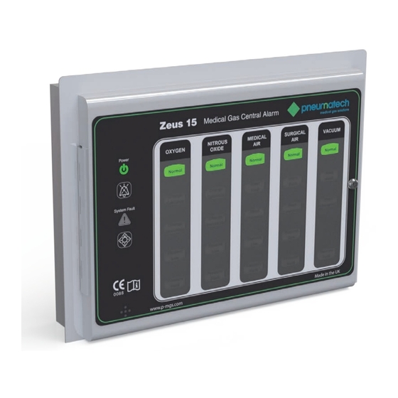
Power source 1.1 Introduction Mains operated using 115V 60Hz or 230V 50Hz, alternat- The Pneumatech MGS Zeus 15 medical gas central ing current, from an essential circuit. Please see labelling alarm system is designed to provide full monitoring of a inside unit for correct voltage. -
Page 6: Standards
TABLE 1.1: Zeus 15 – DIMENSIONS existing alarm systems or building management systems. Alarm Panel Bezel 1.2 Standards Height(mm) 196.0 246.0 The Pneumatech MGS Zeus 15 medical gas central alarm Length(mm) 260.0 310.0 system is specifically designed and manufactured to fully Depth(mm) 61.2 18 swg satisfy the National Health Service –... -
Page 7: Test And Mute Switches
Installation, Operation and Maintenance Manual low or red) to draw attention to the specific alarm condi- The audible tone consists of a modulation between two tion. All flashing displays are programmed at sixty flashes tones (F1 and F2). F1 = 440Hz and F2 = 880Hz. The per minute, 0.5 seconds on and 0.5 seconds off in accor- modulation rate is 4 Hz in accordance with HTM02-01/ dance with C11 and HTM02-01/HTM2022. - Page 8 Installation, Operation and Maintenance Manual terminals connected to matching plug/socket combination to accept the mains electrical power supply, which should be from an essential circuit, and enables connection of FIGURE 1.4 - Zeus 15 LIGHT BOARD flying earth leads which electrically bond the assembly. The power supply PCB should be set to the appropri- SYSTEM ALARM LED NORMAL CONDITION LED’s...
- Page 9 Installation, Operation and Maintenance Manual FIGURE 1.5 - Zeus 15 POWER SUPPLY BOARD CONNECTION LAYOUT AND MOUNTING RETAINING STUD LOCATIONS x 4 MULTI-WAY DATA RIBBON MAIN POWER FROM LIGHT CONNECTION BOARD [BONDING EARTH] [MAIN EARTH] [NEUTRAL] [LIVE] OUTPUT RELAY TRANSMITTING SINGLE EVENT ALARM [COMMON]...
-
Page 10: Alarm Contact Line Fault
CAUTION: break the continuity between terminals C and either 1, 2, Only Pneumatech MGS line continuity monitor modules 3 or 4. Relays are connected to the BMS system at termi- should be fitted, otherwise the SYSTEM ALARM circuits nals C, 1, 2, 3 and 4 and are rated at a maximum voltage could provide spurious indications. - Page 11 Installation, Operation and Maintenance Manual The Zeus 15 medical gas panels use coloured LED’s to indicate the service conditions (see table 3 & 4). During normal conditions, the green NORMAL LED is illuminated. Should a service fault occur, the green (NORMAL) LED is extinguished and the appropriate service fault condition is illuminated (flashing) either by a yellow LED for warning conditions or red LED for emergency conditions, together...
- Page 12 Installation, Operation and Maintenance Manual TABLE 1.2: Zeus 15 ALARM LOGIC – INPUT PANEL Power failure SYSTEM ALARM (flashing) to input Audible (after 30 seconds) panel POWER ON LED extinguished Condition Input Panel - Alarm displays Normal NORMAL (steady) System alarm Power on LED Data All input channels to panel displayed as normal.
- Page 13 Installation, Operation and Maintenance Manual Line NORMAL (steady) Repeater All alarms conditions (flashing) contact fault Alarm conditions (steady) panel display SYSTEM ALARM (flashing) SYSTEM ALARM (flashing) when power Audible Audible fails to a connected input panel Alarm conditions Alarm condition System alarm System alarm Example shows fault on channel 4, column 1...
-
Page 14: Installation
Installation, Operation and Maintenance Manual 2. INSTALLATION 2.1.3 Backbox. Fit (see figure 2.1). 2.1 Installation of a first fix panel Select cable entry/exit points and remove the desired knock-out segments from the inside. Fit suitable grom- The alarm panel backbox is suitable for both surface and mets/cable glands as required by the contract specifica- concealed installation and is annotated ‘TOP’... -
Page 15: Installation Of A Second Fix Assembly
Installation, Operation and Maintenance Manual WARNING...WITH A CONCEALED INSTALLATION, THE PLASTER DEPTH MUST BE FLUSH WITH THE BOX FIGURE 2.3- LEGEND INSTALLATION SURFACE, LEAVING THE WATER CHANNEL PROUD GAS LEGEND INSTALLATION SLOTS OF THE PLASTER. Col. 5 Col. 4 Col. 3 Col. - Page 16 Installation, Operation and Maintenance Manual 2.2.3 Alarm panel front cover. Fit (SEE FIGURE 2.4). Secure the front cover to backbox flange by securing hinge to backbox with screws provided. FIGURE 2.5 - DOOR INSTALLATION DETAIL. BACK BOX DOOR ASSEMBLY M4 x 12 PAN HEAD x 2 M4 x WASHER x 2 2.2.4 Power supply printed circuit board.
- Page 17 The Zeus 15 uses the EIA/TIA-485 (RS-485) data com- not over torque retaining nuts. munications specification. Cable used for the alarm data must be suitable for these signals. Pneumatech MGS rec- 2.2.5 Electrical bonding lead. Fit (see figure 2.7). ommends the following cable types...
- Page 18 Installation, Operation and Maintenance Manual FIGURE 2.8 - Zeus 15 EXAMPLE MAXIMUM OF CABLE SEGMENTS 2 segment network with a single, distant panel. Zeus 15 Zeus 15 Zeus 15 Zeus 15 DATA DATA DATA DATA BOOSTER LENGTH OF SEGMENT <1200 METRES LENGTH OF SEGMENT <1200 METRES 2 segment network arranged as a physical cross.
- Page 19 Zeus 15 Alarm Terminals Zeus 6 Notes... Notes... 1. If connected to Pneumatech MGS plant, line continuity 1. A maximum of four point alarms may be connected to any monitors are integral to the plant. channel. 2. Unused terminals must be linked out with linking resistors 2.
-
Page 20: Programming Of The Alarm System
3.0 Programming of the alarm system 1 – Oxygen Manifold Alarms 2 – Nitrous Oxide Manifold Alarms The Zeus 15 central alarm system panels are programmed 3 – Air Plant Alarms by setting a series of DIL and rotary switches on the rear 4 –... - Page 21 Installation, Operation and Maintenance Manual FIGURE 3.1 - EXAMPLE OF PROGRAMMING SWITCH SETTINGS FOR A TYPICAL INSTALLATION INCLUDING Zeus 15, Zeus 6 Switch settings for example installation SW1 SW2 SW3 SW4 SW5 SW7 SW9 Panel Location Panel Master Panel RS485 Master ID High Mute...
- Page 22 Installation, Operation and Maintenance Manual TABLE 3.2 Zeus 15 PROGRAMMING FIGURE 3.3 - Zeus 15 PROGRAMMING SWITCHES Switch Setting/description PROGRAMMING SWITCHES (SEE SECTION 1.12) Display channel 1 Off, gas display channel not used Display channel 1 Normal gas display HTM02-01 Display channel 2 Off, gas display channel not used Display channel 2 Normal gas...
-
Page 23: Commissioning
Installation, Operation and Maintenance Manual 4. COMMISSIONING 4.5 Check the audible warning 4.1 Introduction Whilst carrying out paragraph 2.4, ensure that audible Commissioning of the Zeus 15 medical gas central alarm warning sounds for the appropriate alarm conditions. En- installation is carried out in full after initial installation and sure the operation of the MUTE switch cancels the audible the appropriate sections must be carried out after a ma- and that the audible comes on again after approximately... -
Page 24: Check Central Acknowledge Function
Installation, Operation and Maintenance Manual els which display that input indicate all ‘alarm conditions’ is pressed or the gas service is returned to normal. If the and SYSTEM ALARM in a flashing mode. mute facility is operated, the audible warning will re-sound after 15 mins, until either the MUTE switch is re-selected Input. - Page 25 Installation, Operation and Maintenance Manual LIGHT BOARD GAS SUPPLY LEGEND MULTI-WAY RIBBON CON- M3 NYLON WASHERS (P/N 6000169) SLOTS NECTOR POWER SUPPLY BOARD (P/N 6000168) LIGHT BOARD FASTENER M3 NUTS (5.5 A/F) POWER BOARD FASTENER M3 NUTS (5.5 A/F) & M3 NYLON WASHERS &...
- Page 26 Installation, Operation and Maintenance Manual FIGURE 5.2 - LIGHT BOARD COMPONENT REPLACEMENT ROW OF GREEN LED’S (P/N 6000152) GREEN POWER ON LED (P/N 6000155) RED SYSTEM ALARM LED (P/N 6000156) SPEAKER CONNECTOR SPEAKER ROW OF RED LED’S (P/N 6000153) ROW OF YELLOW LED’S (P/N 6000154) FIGURE 5.3- BOARD FUNCTION DIAGNOSTIC LED’S LED 4 LED 5...
-
Page 27: Fault Diagnosis
Installation, Operation and Maintenance Manual FIGURE 5.4 - POWER SUPPLY AND LIGHT DISPLAY PCB REPLACEMENT WARNING: ENSURE THAT THE MAINS ELECTRICAL SUPPLY IS OFF AND REMAINS ISOLATED DURING WORK ON THE INTERNALS OF THE ALARM PANEL. CAUTION: Printed circuit boards are susceptible to damage by static electricity and must remain enclosed in their anti-static packaging until immediately required for use. - Page 28 Installation, Operation and Maintenance Manual TABLE 7.3: ALARM PANEL LOSES ALL DISPLAYS EX- CEPT SYSTEM ALARM Remarks/rectification action Possible cause 1. JP1 set Check that the jumper on JP1 is set to Remarks/rectification action Possible cause incorrectly the correct position. 1.
-
Page 29: Recommended Spares
Installation, Operation and Maintenance Manual 1. Check status of other panels which display that particu- Back up battery assembly 6000157 lar gas service. If gas service display is flashing carry out Green LED array 6000152 steps 1-5 inclusive. Yellow LED array 6000154 2. - Page 30 T: 44 (0) 1235 463051 F: 44 (0) 1235 463011 F: 44 (0) 1235 463011 F: 44 (0) 1235 463011 sales@p-nmgs.com spares@p-mgs.com service@p-mgs.com Document 8102341078 Ref. 01. 12/10/2015 © Pneumatech Medical Gas Solutions 2015. All rights reserved. Zeus Central 15 Alarm Page 30...
Need help?
Do you have a question about the Zeus 15 Central Alarm and is the answer not in the manual?
Questions and answers