Advertisement
Advertisement

Summary of Contents for China EM Technology Limited EM11-G1-1d5
- Page 1 EMHEATER User’s Manual EM11 Series Frequency Inverter China EM Technology Limited Address : No.80, Baomin 2 road, Xixiang, Bao'an District,Shenzhen ,China Phone: 86-0755-29985851 Fax: 86-0755-29970305 Zip code: 518101 China EM Technology Limited Website : Http://www.emheater.com...
-
Page 2: Table Of Contents
EM11 User’s Manual Preface Table of Contents EM11 User’s Manual Preface Table of Contents 1. Safety Information and Precautions ......................1 Thank you for purchasing the EM11 series frequency inverter developed by China EM Technology 1.1 Safety Information ..........................1 Limited. - Page 3 EM11 User’s Manual Table of Contents Table of Contents EM11 User’s Manual 3.8.1 Function and description of Main Circuit Terminals ..............24 6.3.6 Precautions for Installing EMC input filter at the input end of power supply ......127 3.9 Cautions for Main Circuit Wiring ......................25 7.
-
Page 4: Safety Information
EM11 User’s Manual 1. Safety Information and Precautions 1. Safety Information and Precautions EM11 User’s Manual Warning 1. Safety Information and Precautions Never connect the power supply cables to the output terminals (U, V, W) of the Frequency inverter. In this manual, the notices are graded based on the degree of danger: Failure to comply will result in damage to the frequency inverter. -
Page 5: During Operation
EM11 User’s Manual 1. Safety Information and Precautions 1. Safety Information and Precautions EM11 User’s Manual 1.1.6 During operation 1.2.4 Vibration of mechanical device The frequency inverter may encounter the mechanical resonance point at some output frequencies, which Danger can be avoided by setting the skip frequency. ... -
Page 6: Product Information
EM11 User’s Manual 1. Safety Information and Precautions 2. Product Information EM11 User’s Manual 1.2.13 Disposal 2. Product Information The electrolytic capacitors on the main circuits and PCB may explode when they are burnt. Poisonous gas is generated when the plastic parts are burnt. Please treat them as industrial waste. 2.1 Designation Rules 1.2.14 Adaptable Motor The standard adaptable motor is adaptable four-pole squirrel-cage asynchronous induction motor. -
Page 7: Technical Specifications
EM11 User’s Manual 2. Product Information 2. Product Information EM11 User’s Manual 2.4 Technical Specifications Adaptable Motor Input Output Power Thermal Power Model Current Current Capacity Consumption Table 2-2 Technical specifications of EM11 (KVA) (KW) Item Specifications EM11- G2-004 14.6 0.132 Vector control: 0~300 Hz Maximum frequency... - Page 8 EM11 User’s Manual 2. Product Information 2. Product Information EM11 User’s Manual Item Specifications Item Specifications The current and voltage are limited automatically during the Standard: Overvoltage/ Over current running process so as to avoid frequently tripping due to 6 digital input (DI) terminals, one of which supports up to 50 stall control overvoltage / over current.
-
Page 9: Product Appearance And Installation Dimension
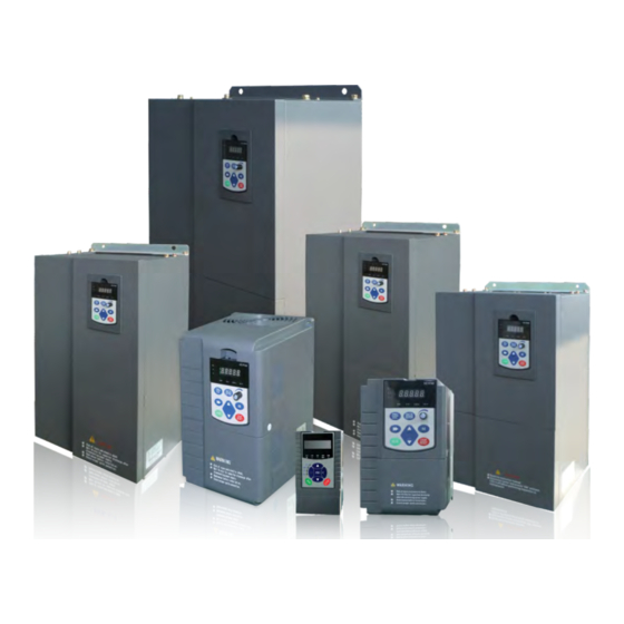
EM11 User’s Manual 2. Product Information 2. Product Information EM11 User’s Manual 2.5 Product appearance and installation dimension Voltage & Power Housing Type 2.5.1 Product appearance Single-phase 220 V 0.4–2.2 kW Plastic housing Three-phase 220 V 0.4–4 kW Plastic housing 5.5–75 kW Sheet metal housing Three-phase 380 V... -
Page 10: Options
EM11 User’s Manual 2. Product Information 2. Product Information EM11 User’s Manual Table 2-4 Options of EM11 frequency inverter Appearance and installing dimension(mm) Model Φd Item Model Functions Remarks EM11- G3-018/P3-022 Single-phase:0.4kw~2.2kw; The internal braking Internal With”-B” after the EM11- G3-022/P3-030 Φ7 unit is optional for Three-phase: 0.75kw~15kw, Standard... -
Page 11: Wearing Parts Replacement
EM11 User’s Manual 2. Product Information 2. Product Information EM11 User’s Manual 2.7.3 Wearing parts replacement 2.9.1 Selection of braking resistance value The wearing parts of frequency inverter include the cooling fan and filting electrolytic capacitor, its service When braking, almost all the renewable energy of motor is consumed on the braking resistor. life is closely related to the using environment and maintenance status. -
Page 12: Installation Of Frequency Inverter
EM11 User’s Manual 2. Product Information 3. Installation of Frequency Inverter EM11 User’s Manual 3. Installation of Frequency Inverter Recommend Recommend Braking Model power of resistance value of Remarks unit braking resistor braking resistor 3.1 Installation environment EM11- G2-075 16k W ≥... -
Page 13: Peripheral Devices Connection Diagram
EM11 User’s Manual 3. Installation of Frequency Inverter 3. Installation of Frequency Inverter EM11 User’s Manual 3.3 Peripheral Devices Connection Diagram 3.4 Instructions of Main Circuit Peripheral Devices Table 3-1 Main circuit peripheral devices use instructions Installation Parts Name Function Description Location The capacity of the circuit breaker shall be 1.5 to 2 times of the rated current of the inverter. -
Page 14: Model Selection Of Main Circuit Peripheral Devices
EM11- G3-090/P3-110 Main Circuit Side Main Circuit Control Circuit Model EM11- G3-110/P3-132 EM11- G3-132/P3-160 Single-phase 220V EM11- G3-160/P3-200 EM11-G1-d75 EM11- G3-200/P3-220 150*2 150*2 EM11-G1-1d5 EM11- G3-220/P3-250 150*2 150*2 EM11-G1-2d2 EM11- G3-250/P3-280 185*2 185*2 Three-phase 220V EM11- G3-280/P3-315 185*2 185*2 EM11-G2-d75... -
Page 15: Connection Terminals Diagram Description
EM11 User’s Manual 3. Installation of Frequency Inverter 3. Installation of Frequency Inverter EM11 User’s Manual 3.8 Sketch and Description of Main Circuit Terminals 3.8.1 Function and description of Main Circuit Terminals 3.8.1.1 Main Circuit Terminals Sketch of single-phase 220V model Including model: Single-phase 220V: EM11-G1-d75~EM11-G1-2d2 Terminal symbol Function description... -
Page 16: Cautions For Main Circuit Wiring
EM11 User’s Manual 3. Installation of Frequency Inverter 3. Installation of Frequency Inverter EM11 User’s Manual 3.9.3 Grounding Wiring 3.8.1.4 Main Circuit Terminals Sketch of Model with optional internal braking units Including model: The inverter will produce leakage current. The higher the carrier frequency is, the larger the leakage Three-phase 220V: EM11-G2-011~EM11-G2-037 current will be. -
Page 17: Control Circuit And Main Circuit Terminals Description
EM11 User’s Manual 3. Installation of Frequency Inverter 3. Installation of Frequency Inverter EM11 User’s Manual It is forbidden to short circuit the shielding layer and other signal cables and the equipment. 3.10.2 Control Circuit Terminal Layout When the inverter is connected to the inductive load equipment (e.g. electromagnetic contactor, relay and solenoid valve), surge suppressor must be installed on the load equipment coil, as showed in Diagram 3-10 Diagram 3-12 EM11 Control Circuit Terminal Sketch Map... -
Page 18: Wiring Of Analog Input Terminals
EM11 User’s Manual 3. Installation of Frequency Inverter 3. Installation of Frequency Inverter EM11 User’s Manual Terminal Terminal 3.10.5 Wiring of Multi-functional Input Terminals Type Terminal function description Symbol Name Optical coupling isolation, dual polarity open collector output. Output voltage range: 0V~24 V Output current range: 0mA~50 mA Digital output DO1-CME... -
Page 19: Description Of Control Circuit Jumper
EM11 User’s Manual 3. Installation of Frequency Inverter 4. Operation and display EM11 User’s Manual please install a fly-wheel diode to the two sides of relay. Please correctly install the polarity of fly-wheel 4. Operation and display diode, otherwise control card and DSP can be damaged. 3.10.7 Description of Control Circuit Jumper 4.1 Instruction of operation and display Jumper Name... -
Page 20: Viewing And Modifying Function Codes
EM11 User’s Manual 4. Operation and display 4. Operation and display EM11 User’s Manual RUN: OFF indicates that the frequency inverter is in the stop state and ON indicates that the frequency inverter is in the running state. LOCAL: It indicates whether the frequency inverter is operated by operation keypad, terminals or remoter (communication). -
Page 21: The Operation Of User-Defined Fast Menu Of Parameters
EM11 User’s Manual 4. Operation and display 4. Operation and display EM11 User’s Manual Parameter Display Mode Display d2-00 V/F curve setting Base mode -dFLt d2-01 Torque boost User-defined mode -user User can modify the user-defined fast menu based on actual requirements. User-modified mode -chGd 4.5 Monitoring Status Parameters... -
Page 22: Description Of Function Codes
EM11 User’s Manual 4. Operation and display 5. Description of Function Codes EM11 User’s Manual Motor Parameter 5. Description of Function Codes b0-00:Motor Type Selection d0-00:Motor Rated Power Motor 1 d0-01:Motor Rated Voltage d0-02:Motor Rated Current 5.1 Group b0: Basic Function Parameters d0-03:Motor Rated Frequency d0-04:Motor Rated Speed Code... - Page 23 EM11 User’s Manual 5. Description of Function Codes 5. Description of Function Codes EM11 User’s Manual Commands are given by pressing keys “RUN” and “STOP/RESET” on the operation panel. The relation between DI6 terminal input pulse frequency and corresponding setting is set by b5-00~ b5-03. The corresponding relation is the linear relation of these two points.
- Page 24 EM11 User’s Manual 5. Description of Function Codes 5. Description of Function Codes EM11 User’s Manual If X and Y operation is used, b0-05 and b0-06 are used to set the adjustment range of the auxiliary This parameter is valid only when the frequency source is set to "X and Y operation". The final frequency is frequency source.
- Page 25 EM11 User’s Manual 5. Description of Function Codes 5. Description of Function Codes EM11 User’s Manual Code Parameter Name Setting Range Default corresponding frequency values change display. 0: Forward direction This parameter is not restored when factory fault setting is done. b0-18 Rotation direction 1: Reverse direction...
-
Page 26: Group B1: Start/Stop Control Parameters
EM11 User’s Manual 5. Description of Function Codes 5. Description of Function Codes EM11 User’s Manual Code Parameter Name Setting Range Default 0.00s~650.00s (b0-25 = 2) Model b0-22 0.0s~6500.0s (b0-25 = 1) Deceleration time 1 dependent 0s~65000s (b0-25 = 0) Acceleration time indicates the time required by the frequency inverter to accelerate from 0 Hz to "Acceleration / Deceleration base frequency"... - Page 27 EM11 User’s Manual 5. Description of Function Codes 5. Description of Function Codes EM11 User’s Manual frequency. Startup DC braking is generally used during restart of the frequency inverter after the rotating motor stops. Pre-excitation is used to make the frequency inverter build magnetic field for the asynchronous motor before If the pre-excited time is not 0, the frequency inverter pre-excites firstly before startup, improving the startup to improve the responsiveness.
-
Page 28: Group B2: Auxiliary Functions
EM11 User’s Manual 5. Description of Function Codes 5. Description of Function Codes EM11 User’s Manual Code Parameter Name Setting Range Default b2-09 0.00 Hz ~maximum frequency Jump frequency 1 0.00 Hz b2-10 0.00 Hz ~ maximum frequency Jump frequency 2 0.00 Hz b2-11 0.00 Hz ~ maximum frequency... - Page 29 EM11 User’s Manual 5. Description of Function Codes 5. Description of Function Codes EM11 User’s Manual Code Parameter Name Setting Range Default Frequency switchover point b2-13 0.00 Hz ~ maximum frequency 0.00 Hz between acceleration time 1 and acceleration time 2 Frequency switchover point b2-14 0.00 ~ maximum frequency...
-
Page 30: Group B3: Input Terminals
EM11 User’s Manual 5. Description of Function Codes 5. Description of Function Codes EM11 User’s Manual It is used to set the accumulative running time threshold of the Frequency inverter. If the accumulative Code Parameter Name Setting Range Default running time (b9-09) reaches the value set in this parameter, the corresponding DO terminal becomes ON. This time running time b2-31 0.0min~6500.0 min... - Page 31 EM11 User’s Manual 5. Description of Function Codes 5. Description of Function Codes EM11 User’s Manual Value Function Description Value Function Description Multi-function terminal 1 The terminal is used to restore the original status of PLC control The setting of 16 speeds or 16 other references can be PLC status reset for the frequency inverter when PLC control is started again Multi-function terminal 2...
- Page 32 EM11 User’s Manual 5. Description of Function Codes 5. Description of Function Codes EM11 User’s Manual Value Function Description This parameter is used to set the mode in which the frequency inverter is controlled by external terminals. The following uses DI1, DI2 and DI3 among DI1 to DI12 as an example, with allocating functions of DI1, After this terminal becomes ON, the frequency inverter directly Immediate DC braking DI2 and DI3 by setting b3-00 to b3-02.
-
Page 33: Group B4: Output Terminals
EM11 User’s Manual 5. Description of Function Codes 5. Description of Function Codes EM11 User’s Manual 1. If b0-11 (Frequency reference resolution) is 2, the setting range is 0.001Hz/s~65.535 Hz/s. Code Name Value Function Description 2. If b0-11 (Frequency reference resolution) is 1, the setting range is 0.01Hz/s~655.35 Hz/s. b3-13 Terminal command mode Three-line 1... - Page 34 EM11 User’s Manual 5. Description of Function Codes 5. Description of Function Codes EM11 User’s Manual FM terminal (used for high-speed pulse output or open-collector switch signal output) as standard. If these Value Function Description output terminals cannot satisfy requirements, use an optional I/O extension card. If the frequency inverter runs with the output frequency of 0, the Zero-speed running (no terminal becomes ON.
- Page 35 EM11 User’s Manual 5. Description of Function Codes 5. Description of Function Codes EM11 User’s Manual the running frequency is lower than value of b4-22, the DO terminal goes OFF. Value Function Description These two parameters are respectively used to set the detection value of output frequency and hysteresis If a fault occurs on the frequency inverter and the frequency inverter Alarm output (all faults) value of cancellation of the output.
- Page 36 EM11 User’s Manual 5. Description of Function Codes 5. Description of Function Codes EM11 User’s Manual Diagram 5-15 Detection range of frequency reached Diagram 5-16 Any frequency reaching detection Code Parameter Name Setting Range Default Code Parameter Name Setting Range Default Any frequency reaching b4-31...
-
Page 37: Group B5: Pulse/Analog Input Terminals
EM11 User’s Manual 5. Description of Function Codes 5. Description of Function Codes EM11 User’s Manual 5.6 Group b5: Pulse/Analog input terminals Code Parameter Name Setting Range Default b5-00 Pulse minimum input(HDI) 0.00 kHz ~b5-02 0.00 kHz Corresponding setting of pulse b5-01 -100.00% ~100.0% 0.00%... - Page 38 EM11 User’s Manual 5. Description of Function Codes 5. Description of Function Codes EM11 User’s Manual Code Parameter Name Setting Range Default Code Parameter Name Setting Range Default fourth point input value of AI1 Corresponding setting of b5-15 AI1 input maximum value 0.00 V ~ 10.00 V 10.00 V b5-23...
-
Page 39: Group B6: Pulse/Analog Output Terminals
EM11 User’s Manual 5. Description of Function Codes 5. Description of Function Codes EM11 User’s Manual Code Parameter Name Setting Range Default 0.00V corresponds to 0.00% and maximum input 10.00V corresponds to 100.0%。 The detected AI1 input b6-05 AO1 gain -10.00~10.00 1.00 corresponding setting varies between 49.0% and 51.0%. - Page 40 EM11 User’s Manual 5. Description of Function Codes 5. Description of Function Codes EM11 User’s Manual Different from DI terminals, VDI state can be set in two modes, selected in b7-05: For example 1:Decided by state of VDOx Whether the state of VDI is valid or not, that is determined by the state of the corresponding VDO. VDI x is uniquely bound to VDO x (x is one of 1~5).
-
Page 41: Group B8: Ai/Ao Correction
EM11 User’s Manual 5. Description of Function Codes 5. Description of Function Codes EM11 User’s Manual 5.9 Group b8: AI/AO Correction Code Parameter Name Setting Range Default Ideal voltage of AO1 b8-12 0.500~4.000 V 2.000V Code Parameter Name Setting Range Default calibration 1 Ideal voltage of AI1... - Page 42 EM11 User’s Manual 5. Description of Function Codes 5. Description of Function Codes EM11 User’s Manual Code Parameter Name Setting Range Default You can change the direction of the frequency inverter running by using the MF.K key. It is valid only when the present command source is operation panel control.
-
Page 43: Group Ba: Communication Parameters
EM11 User’s Manual 5. Description of Function Codes 5. Description of Function Codes EM11 User’s Manual Code Parameter Name Setting Range Default Code Parameter Name Setting Range Default 0: 0 decimal display Unit's digit: Modbus baud ratio. Number of decimal 1: 1 decimal display 0: 300 BPS b9-06... -
Page 44: Group Bb: Fault And Protection
EM11 User’s Manual 5. Description of Function Codes 5. Description of Function Codes EM11 User’s Manual Code Parameter Name Setting Range Default (Err16). At normal application, it will be set as invalid. If in the continuous communication system, setting Motor overload this parameter, you can monitor the communication status. - Page 45 EM11 User’s Manual 5. Description of Function Codes 5. Description of Function Codes EM11 User’s Manual Code Parameter Name Setting Range Default function. This function will be carried out by frequency inverter, when the current exceeds bb-07. This value Time interval of is the percentage of motor rated current.
- Page 46 EM11 User’s Manual 5. Description of Function Codes 5. Description of Function Codes EM11 User’s Manual If the actual motor rotational speed detected by the frequency inverter exceeded the maximum frequency and the excessive value is greater than the value of bb-17 and the lasting time exceeded the value of bb-18, the frequency inverter reports Err43 and acts according to the selected fault protection action.
- Page 47 EM11 User’s Manual 5. Description of Function Codes 5. Description of Function Codes EM11 User’s Manual Code Parameter Name Setting Range Default Code Parameter Name Setting Range Default Unit's digit: Motor overload, Err11. Overvoltage bb-28 200.0~2500.0 V 830.0 V 0: Free stop threshold 1: Stop according to the stop mode It is used to set the overvoltage threshold of the frequency inverter.
-
Page 48: Group Bc: Fault Detection Parameters
EM11 User’s Manual 5. Description of Function Codes 5. Description of Function Codes EM11 User’s Manual frequency is set in bb-36. Code Parameter Name Description Code Parameter Name Setting Range Default Running time of It displays the present running time when the latest fault occurs. bC-10 0: Current running frequency latest fault... - Page 49 EM11 User’s Manual 5. Description of Function Codes 5. Description of Function Codes EM11 User’s Manual 0: Forward action When the feedback value is smaller than the PID setting, the frequency inverter's output frequency rises. For example, the winding tension control requires forward PID action. 1: Reverse action When the feedback value is smaller than the PID setting, the frequency inverter's output frequency reduces.
- Page 50 EM11 User’s Manual 5. Description of Function Codes 5. Description of Function Codes EM11 User’s Manual Code Parameter Name Setting Range Default Code Parameter Name Setting Range Default PID parameter C0-16 PID initial value 0.0%~100.0% 0.0% C0-14 C0-13 ~ 100.0% 80.0% switchover deviation PID initial value...
-
Page 51: Group C1:Multi-Function
EM11 User’s Manual 5. Description of Function Codes 5. Description of Function Codes EM11 User’s Manual Code Parameter Name Setting Range Default C0-21 and C0-22 respectively are corresponding to the maximum absolute value of the output deviation in C1-10 Multi-function 10 -100.0%~100.0% 0.0% forward direction and in reverse direction. - Page 52 EM11 User’s Manual 5. Description of Function Codes 5. Description of Function Codes EM11 User’s Manual Code Parameter Name Setting Range Default Running time of simple C2-08 0.0s(h)~6553.5s(h) 0.0s (h) PLC Segment 3 Acceleration/deceleration C2-09 time of simple PLC Segment 3 Running time of simple C2-10 0.0s(h)~6553.5s(h)
-
Page 53: Group C3: Swing Frequency, Fixed Length And Count
EM11 User’s Manual 5. Description of Function Codes 5. Description of Function Codes EM11 User’s Manual Code Parameter Name Setting Range Default It is variable swing amplitude system. The swing amplitude varies with the central frequency (setting Acceleration/deceleration frequency). C2-27 time of simple PLC 1: Relative to the maximum frequency (b0-13 maximum output frequency) Segment 12... -
Page 54: Group D0: Motor 1 Parameters
EM11 User’s Manual 5. Description of Function Codes 5. Description of Function Codes EM11 User’s Manual Code Parameter Name Setting Range Default During the fixed length control, the length reset operation can be performed via the DI terminal. For details, 0.01A ~ d0-02 (Frequency inverter power ≤55 kW) No-load current Model... - Page 55 EM11 User’s Manual 5. Description of Function Codes 5. Description of Function Codes EM11 User’s Manual Code Parameter Name Setting Range Default Code Parameter Name Setting Range Default 0: ABZ incremental encoder Encoder wire-break 0.0s: No action d0-29 0.0s fault detection time 1: Resolver 0.1s~10.0s d0-20...
-
Page 56: Group D1: Motor 1 Vector Control Parameters
EM11 User’s Manual 5. Description of Function Codes 5. Description of Function Codes EM11 User’s Manual Code Parameter Name Setting Range Default 12: Synchronous motor no-load auto-tuning Speed loop integral If the synchronous motor can be disconnected from the load, no-load auto-tuning is recommended, which d1-05 0.01s~10.00s 1.00s... - Page 57 EM11 User’s Manual 5. Description of Function Codes 5. Description of Function Codes EM11 User’s Manual Code Parameter Name Setting Range Default Code Parameter Name Setting Range Default Torque current loop 0: Invalid field weakening PM field weakening d1-13 0~30000 1300 integral gain d1-21...
-
Page 58: Group D2: Motor 1 V/F Control Parameters
EM11 User’s Manual 5. Description of Function Codes 5. Description of Function Codes EM11 User’s Manual However, in applications requiring rapid torque response, set the acceleration/deceleration time in torque 0: Digital setting (d1-27) The target torque directly uses the value set in d1-27. control to 0.00s. - Page 59 EM11 User’s Manual 5. Description of Function Codes 5. Description of Function Codes EM11 User’s Manual Code Parameter Name Setting Range Default When d2-00 set to 1, these six parameters are used to define the multi-point V/F curve. Cut-off frequency of 0.0%~80.0% The multi-point V/F curve is set based on the motor's load characteristic.
-
Page 60: Group D3 To D5: Relevant Parameters Of Motor 2
EM11 User’s Manual 5. Description of Function Codes 5. Description of Function Codes EM11 User’s Manual Code Parameter Name Setting Range Default as t1 in the following figure. 0: Digital setting (d2-13) 1: AI1 2: AI2 3: AI3 Voltage source for 4: Pulse setting (DI6) d2-12 V/F separation... -
Page 61: Group U0: Monitoring Parameters
EM11 User’s Manual 5. Description of Function Codes 5. Description of Function Codes EM11 User’s Manual The factory setting of carrier frequency varies with the frequency inverter power. If you need to modify the The setting of random PWM depth can make the motor shrill noise to soft and reduce the electromagnetic carrier frequency, note that if the set carrier frequency is higher than factory setting, it will lead to an interference to other equipments. - Page 62 EM11 User’s Manual 5. Description of Function Codes 5. Description of Function Codes EM11 User’s Manual It displays the frequency inverter's output power in the running state. If b0-11 (frequency command resolution) is set to 1, the display range is -3000.00~3000.00 Hz. ...
- Page 63 EM11 User’s Manual 5. Description of Function Codes 5. Description of Function Codes EM11 User’s Manual Code Parameter Name Display Range Code Parameter Name Display Range 0.00Hz~300.00 Hz DI input state visual U0-30 U0-40 Auxiliary frequency Y display 0.0Hz~3000.0 Hz It displays the DI state visually and the display format is shown in the following figure.
-
Page 64: Group A0: System Parameters
EM11 User’s Manual 5. Description of Function Codes 5. Description of Function Codes EM11 User’s Manual Code Parameter Name Setting Range Default It displays the phase Z counting of the present ABZ or UVW encoder. The value increases or decreases by Model 1 every time the encoder rotates a round forwardly or reversely. -
Page 65: Group A1: User-Defined Function Codes
EM11 User’s Manual 5. Description of Function Codes 5. Description of Function Codes EM11 User’s Manual Code Parameter Name Setting Range Default 0:No operation code 14 1: Restore default settings except motor parameters User-defined function If A0-09 is set to 1, most function codes are restored to the default settings except motor parameters, A1-15 User visible function codes ud2.01... -
Page 66: Emc (Electromagnetic Compatibility)
EM11 User’s Manual 6. EMC(Electromagnetic compatibility) 6. EMC(Electromagnetic compatibility) EM11 User’s Manual shielding layer shall be earthed reliably. 6. EMC (Electromagnetic compatibility) 4) When the length of motor cable is longer than 100 meters, it needs to install output filter or reactor. 6.3.3 Handling method for the interferences of the surrounding equipment on the 6.1 Definition inverter... - Page 67 EM11 User’s Manual 6. EMC(Electromagnetic compatibility) 7. Fault Diagnosis and Solution EM11 User’s Manual power is high, the corresponding leakage current will be high too. 7. Fault Diagnosis and Solution 2) Factors of producing leakage current between the cables and solutions: There is distributed capacitance between the output cables of the inverter.
- Page 68 EM11 User’s Manual 7. Fault Diagnosis and Solution 7. Fault Diagnosis and Solution EM11 User’s Manual Fault Name Display Possible Causes Solutions Fault Name Display Possible Causes Solutions 1: The output circuit is grounded or short 1: The three-phase power input is 1: Eliminate external faults.
- Page 69 EM11 User’s Manual 7. Fault Diagnosis and Solution 7. Fault Diagnosis and Solution EM11 User’s Manual Fault Name Display Possible Causes Solutions Fault Name Display Possible Causes Solutions 1: Check the temperature sensor Frequency 1: Overvoltage exists. 1: Handle based on over voltage. cabling and eliminate the cabling inverter Err22...
- Page 70 EM11 User’s Manual 7. Fault Diagnosis and Solution Appendix I EM11 User’s Manual Fault Possible Causes Solutions 1: The setting of carrier frequency is too Appendix I. Modbus communication protocol high. 1: Reduce the carrier frequency Err14 ( IGBT 2: The cooling fan is damaged, or the air (d6-00).
- Page 71 EM11 User’s Manual Appendix I Appendix I EM11 User’s Manual response to the data. Here, master is personnel computer (PC), industrial machine or programmable logical controller (PLC), and the slave is inverter. Master not only visits some slave, but also sends the broadcast information to all the slaves.
- Page 72 EM11 User’s Manual Appendix I Appendix I EM11 User’s Manual Data(H) It indicates the replying data or the data waiting to write-in. During the Definition of communication parameter address transmission, high bit is put in the front, and low bit is at the back. Read and write function-code parameters (Some functional code is not changed, only for the manufacturer Data(L) use.)
- Page 73 EM11 User’s Manual Appendix I Appendix I EM11 User’s Manual Control command input frequency inverter: (write in only) Pulse output control: (write in only) Command word address Command function Command word address Command function 0001: Forward running 2004 0~7FFF indicates 0%~100% 0002: Reverse running 0003: Forward jog Inverter fault description:...
- Page 74 EM11 User’s Manual Appendix I Appendix I EM11 User’s Manual Code Parameter Name Setting Range Default Code Parameter Name Setting Range Default Unit's digit: Modbus baud ratio. Modbus protocol data Unit's digit: Modbus protocol. 0: 300 BPS bA-06 0: Non-standard Modbus protocol transmission format 1: 600 BPS 1: Standard Modbus protocol...
- Page 75 EM11 User’s Manual Appendix II Appendix II EM11 User’s Manual Code Parameter Name Setting range Default Property Appendix II. Function Code Table Auxiliary frequency The same as b0-03 (Main frequency source b0-04 ★ source Y selection X selection) If A0-00 is set to a non-zero number, parameter protection is enabled. You must write in correct user Selection of auxiliary 0: Relative to maximum frequency b0-05...
- Page 76 EM11 User’s Manual Appendix II Appendix II EM11 User’s Manual Code Parameter Name Setting range Default Property Code Parameter Name Setting range Default Property 1: 0.1 Hz Rotational speed b0-11 Frequency unit ☆ b1-02 1~100 ★ 2: 0.01 Hz tracking speed b0-12 Preset frequency 0.00 ~ maximum frequency (b0-13)
- Page 77 EM11 User’s Manual Appendix II Appendix II EM11 User’s Manual Code Parameter Name Setting range Default Property Code Parameter Name Setting range Default Property Frequency switchover 0: No function point between 1: Forward RUN (FWD) or running b2-13 0.00 Hz ~ maximum frequency 0.00 Hz ☆...
- Page 78 EM11 User’s Manual Appendix II Appendix II EM11 User’s Manual Code Parameter Name Setting range Default Property Code Parameter Name Setting range Default Property 38: Normally open (NO) input of external Unit's digit: DI6 valid mode. DI9 function fault 0, 1 (same as DI1) b3-08 ★...
- Page 79 EM11 User’s Manual Appendix II Appendix II EM11 User’s Manual Code Parameter Name Setting range Default Property Code Parameter Name Setting range Default Property 26: Zero current state Frequency detection b4-24 0.00Hz ~ maximum frequency 50.00 Hz ☆ 27: Output current exceeded limitation value (FDT2) b4-06 DO3 function(extend)
- Page 80 EM11 User’s Manual Appendix II Appendix II EM11 User’s Manual Code Parameter Name Setting range Default Property Code Parameter Name Setting range Default Property of AI2 maximum input Corresponding setting b5-08 -100.00% ~100.0% 0.0% ☆ b5-30 AI2 input filter time 0.00s~10.00s 0.10s ☆...
- Page 81 EM11 User’s Manual Appendix II Appendix II EM11 User’s Manual Code Parameter Name Setting range Default Property Code Parameter Name Setting range Default Property Unit's digit: VDI1. 6: Motor rotational speed corresponding to 0: Invalid 0~Max. operation frequency 1: Valid 7: Output current corresponding to 0~1000A Ten's digit: VDI2 AO1 output function...
- Page 82 EM11 User’s Manual Appendix II Appendix II EM11 User’s Manual Code Parameter Name Setting range Default Property Code Parameter Name Setting range Default Property Measured voltage of Unit's digit: VDO1. b8-17 0.500~4.000 V 2.000V ☆ AO2 calibration 1 0: Positive logic valid Ideal voltage of AO2 1: Reverse logic valid b8-18...
- Page 83 EM11 User’s Manual Appendix II Appendix II EM11 User’s Manual Code Parameter Name Setting range Default Property Code Parameter Name Setting range Default Property 0000~FFFF Unit's digit: Modbus baud ratio. Bit00: PID feedback 0: 300 BPS Bit01: PLC stage 1: 600 BPS Bit02: Pulse input frequency (kHz) 2: 1200 BPS Bit03: Running frequency 2 (Hz)
- Page 84 EM11 User’s Manual Appendix II Appendix II EM11 User’s Manual Code Parameter Name Setting range Default Property Code Parameter Name Setting range Default Property Time interval of fault Unit's digit: Motor overload, Err11. bb-11 0.1s~100.0s 1.0s ☆ auto reset 0: Free stop Input phase loss 1: Stop according to the stop mode protection/contactor...
- Page 85 EM11 User’s Manual Appendix II Appendix II EM11 User’s Manual Code Parameter Name Setting range Default Property Code Parameter Name Setting range Default Property DC Bus voltage of 1st Unit's digit: Speed deviation too large, Err42 bC-21 – – ● fault Same as unit's digit in bb-32 Input terminal status of...
- Page 86 EM11 User’s Manual Appendix II Appendix II EM11 User’s Manual Code Parameter Name Setting range Default Property Code Parameter Name Setting range Default Property switchover deviation 2 1: AI1 2: AI2 Unit's digit: Integral separated. 3: AI3 0: Invalid 4: Pulse setting(DI6) 1: Valid 5: PID C0-15...
- Page 87 EM11 User’s Manual Appendix II Appendix II EM11 User’s Manual Code Parameter Name Setting range Default Property Code Parameter Name Setting range Default Property Acceleration/deceleratio Segment 14 C2-13 n time of simple PLC ☆ Running time of simple C2-32 0.0s(h)~6553.5s(h) 0.0s (h) ☆...
- Page 88 EM11 User’s Manual Appendix II Appendix II EM11 User’s Manual Code Parameter Name Setting range Default Property Code Parameter Name Setting range Default Property motor) 0.001mH~65.535 mH (Frequency inverter auto-tuning power ≥75 kW) 11: Synchronous motor with-load 0.1mH~6553.5 mH (Frequency inverter auto-tuning Mutual inductive power≤...
- Page 89 EM11 User’s Manual Appendix II Appendix II EM11 User’s Manual Code Parameter Name Setting range Default Property Code Parameter Name Setting range Default Property d1-18 Motor running slip gain 50%~200% 100% Acceleration time in ☆ d1-32 0.00s~120.00s 0.10s ☆ torque control d1-19 Braking slip gain 50%~200%...
- Page 90 EM11 User’s Manual Appendix II Appendix II EM11 User’s Manual Code Parameter Name Setting range Default Property Code Parameter Name Setting range Default Property for V/F separation power ≥75 kW) 0.0s~1000.0s Back EMF Model Voltage rise time of V/F d3-18 0.1V~6553.5 V ★...
- Page 91 EM11 User’s Manual Appendix II Appendix II EM11 User’s Manual Code Parameter Name Setting range Default Property Code Parameter Name Setting range Default Property time 0: Digital setting (d4-27) 1: AI1 Excitation current loop d4-10 0~30000 2000 ☆ proportional gain 2: AI2 3: AI3 Excitation current loop...
- Page 92 EM11 User’s Manual Appendix II Appendix II EM11 User’s Manual Code Parameter Name Setting range Default Property Code Parameter Name Setting range Default Property 0.0%~80.0% d6-05 Dead zone 0: No compensation Cut-off frequency of d5-02 Actual cut-off frequency= Motor rated 50.0% ★...
- Page 93 EM11 User’s Manual Appendix II Appendix II EM11 User’s Manual Code Parameter Name Setting range Default Property Code Parameter Name Setting range Default Property AI2 voltage before Received value of U0-22 0.00V~10.57 V ● correction U0-50 point-point -100.00%~100.00% ● AI3 voltage before communication U0-23 -10.57V~10.57 V...
-
Page 94: Warranty Agreement
User visible function codes uA0.00 ☆ 6) If there is any problem during the service, contact EMHEATER’s agent or EMHEATER directly. code 17 7) This agreement shall be interpreted by China EM Technology Limited. User-defined function A1-18 User visible function codes uA0.00 ☆...
Need help?
Do you have a question about the EM11-G1-1d5 and is the answer not in the manual?
Questions and answers