Table of Contents
Advertisement
Advertisement
Table of Contents

Summary of Contents for JFRMEDICAL Cube 30 ATV
- Page 1 JFR Medical Instruments GmbH Ostuferhafen 15, 24149 Kiel, Germany T: 0431 - 7298 740-0, F: 0431 - 7298 740-19 Cube 30 ATV E: info@jfr-gmbh.de Customer Service: Ventilator Version 04/2017 - User Manual, Cube 30 ATV, English Software Version: 1.X.X User Manual...
-
Page 2: Table Of Contents
TABLE OF CONTENTS 1. INTRODUCTION ........1.1 Intended use ........1.2 Contraindication . - Page 3 9. SCOPE OF DELIVERY ........54 9.1 Standard scope of delivery Cube 30 ATV ... . . 9.2 Accessories/spare parts ......
-
Page 4: Introduction
1.2 Contraindication The Cube 30 ATV is not a life-supporting system and may therefore not be used by patients that are only able to tolerate short interruptions in ventilation. The use of the device could also be contraindicated among patients who suffer from the following conditions: •... -
Page 5: Side Effects
• Hypotension, particularly combined with intravascular volume depletion • Fluid discharge, short-term cranial operation or trauma • Acute sinus or middle-ear inflammation • Dehydration • Severe bullous pulmonary inflammation. 1.3 Side effects Please contact your doctor immediately if you experienced severe headache, unusual chest pain or shortness of breath. -
Page 6: Overview Of The Device
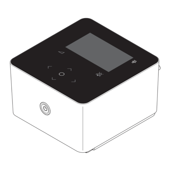
2. OVERVIEW OF THE DEVICE You will find the scope of supply included as standard in section 9.1 on Page 54. Control panel with display Start/stop button Safety clip (mains cable) Mains socket USB A connection Micro USB connection Air outlet (if used without respira- tory humidifier) and silicone cover for air outlet Loudspeaker... - Page 7 11. Connection socket for respiratory humidifier 12. Type plate 13. Air outlet (if used with respiratory humidifier) 14. LED for respiratory humidifier 15. Audio-pause key 16. Navigation buttons 17. OK key 18. Ramp key 19. Display Overview of the device...
-
Page 8: Accessories
2.1 Accessories 2.1.1 Optional respiratory humidifier (not yet available at the moment) 20. Lock clamp 21. Air inlet of the respiratory humidifier 22. Air outlet 23. Connection socket for respiratory device 24. Release button 25. Heating plate 26. Cover for water chamber 27. Opening lever to the water cham- 28. - Page 9 32. Type plate to the respiratory humid- ifier 33. Storage compartment for the sili- cone cover of the power connector (if respiratory humidifier is used) 2.1.2 Further accessories Tube system in accordance with ISO 5367 Respiratory mask (diagram, not included in the scope of supply) Overview of the device...
- Page 10 Bacterial filter (diagram, not included in the scope of supply) Mains cable (EU type) Transport bag Overview of the device...
-
Page 11: Explanation Of Symbols
2.2 Explanation of symbols Symbols on type plate Symbol Meaning Manufacturer Date of manufacture Serial number Model number Alternating current Protection rating II Type BF application part Protection from: IP21 + spillage Protection against the ingress of solid foreign bodies ≥ 12.5 mm IP21 diameter and larger, and against vertically falling water droplets plus spillage CE declaration of conformity The device cannot be disposed of in domestic waste. - Page 12 Symbols on the device Symbol Meaning Follow user instructions Alternating current USB connections Loudspeaker Symbols in the clinical manual Symbol Meaning WARNING This symbol designates an extraordinarily dangerous situation. Fail- ure to follow this information can result in serious injuries and even death. CAUTION This symbol designates a dangerous situation. Failure to follow this information can result in slight or moderate injuries.
-
Page 13: Putting The Device Into Service
3. PUTTING THE DEVICE INTO SERVICE 3.1 Setting up the device Warning Take care when setting up the device that the air inlet on the back of the device is not blocked by cur- tains, bedding etc. • Ensure that the device is put into service by following the instructions below. - Page 14 Connect the power mains cable to the device. Secure the power cable to the device with the help of the safety clip. Insert the other end of the mains cable into a socket. Connect the respiratory tube on the air outlet on the back of the device. Connect the other end of the respiratory tube to the mask.
- Page 15 With respiratory humidifier (not yet available) Check that the opening for the air outlet on the back of the device is closed with the silicone cover. Ensure that the silicone cover for the respiratory humidifier's connection socket under the device has been removed. There is a storage recess for the silicone cover of the connection under- neath the respiratory humidifier.
- Page 16 Connect the respiratory humidifier to the device. To do this, place the device on the respiratory humidifier so that it is connected on the front. Ensure that the lock clamp of the respiratory humidifier hooks into the corresponding lugs of the device. Press the back of the device down. Connect the power mains cable to the device.
-
Page 17: Fitting The Respiratory Mask
Connect the respiratory tube to the air outlet on the respiratory humidi- fier. Connect the other end of the respiratory tube to the mask. 3.3 Fitting the respiratory mask Note The device requires a respiratory mask with integrated air outlet. Other- wise, CO may be reinhaled. -
Page 18: Connecting Bacterial Filter
3.4 Connecting bacterial filter If the plan is to use the device with several patients Warning (e.g. in a small clinic), it is necessary to provide the device with a bacterial filter to protect it from conta- mination with bacteria. The bacterial filter is placed between the device's air outlet and the tube sys- tem. -
Page 19: Using The Device Daily
4. USING THE DEVICE DAILY 4.1 Starting therapy Do not carry out therapy while the device is con- Warning nected to the PC via the USB port. • Put on the respiratory mask. For detailed information on the correct fit of the respiratory mask please refer to the manufacturer information. •... -
Page 20: Switching Therapy Sets
(off, 1-5, in 1 steps). • The device saves the step set so that it may be started when it is next used. • The heating plate can be switched off to use the device with a humidifier connected not using humidification. 4.3 Switching therapy sets The device enables the user to choose one of two therapy sets. - Page 21 The colour of the alarm status bar varies depending on the alarm's priority that has occurred (red for high priority, yellow for medium priority and turquoise for low priority). If the device is in the standby state (i.e. has not been operated for at least two minutes) an alarm list that completes the entire display appears and an acous- tic signal sounds.
- Page 22 4.4.1 Pausing alarms • You can switch the acoustic alarm to pause for the duration of two minutes by pressing the "Audio pause" key. • After a period of two minutes the device reactivates the acoustic signal if the triggering event is still present. •...
-
Page 23: Stopping Therapy
4.5 Stopping therapy • Remove the respiratory mask. • Press the start/stop button for the period of 3 seconds. Therapy is stopped when you release the button. The device signals that therapy has been switched off by a beep and by notification in the display. - Page 24 You may need a travel plug adapter to be able to use the power cable in the destination country. The Cube 30 ATV can be used on the plane if the plane is operated via a 100- 240 V AC power source.
-
Page 25: Functional Description
5. FUNCTIONAL DESCRIPTION This chapter has only informative character. The therapy settings shall only be adjusted by a doctor and cannot be changed by the patient. 5.1 General function of the device The device sucks ambient air through the filter system into the device where it is compressed by the blower unit. - Page 26 then returns, released by the patient exhaling into the EPAP (Expiratory Pos- itive Airway Pressure). If the patient does not exhale for a set period (can be set by Ti max), the device switches to EPAP latest after the set period. PCV / Bilevel T Pressure Controlled Ventilation.
-
Page 27: Additional Therapy Functions
5.3 Additional therapy functions The device also offers the following therapy functions. 5.3.1 Ramp To make the start of therapy more pleasant for the patient, there is the option to set a ramp, through which the pressure level is slowly raised up to the ther- apy pressure. - Page 28 Display Priority Leakage Non vented mask Moderate Low minute volume Moderate High respiratory rate Low respiratory rate Moderate Target volume not reached Moderate Target minute volume not reached Moderate Functional description...
-
Page 29: Setting The Device
6. SETTING THE DEVICE 6.1 Control panel The standby screen appears on the display when you switch on the device. The navigation buttons are underneath the display with the left, right, up and down keys. There is an OK button in the middle of the navigation buttons. Only the keys that currently have a function are lit. -
Page 30: Standby Screen
When setting up parameters you are able to change the pa- rameter value by pressing the right/left keys and confirm the set value by pressing the OK key. To cancel the setting operation and leave the submenu, press the up key until the Cancel field is selected and confirm Cancel with the OK key. - Page 31 With ongoing therapy the current status is displayed on the right-hand side by means of different measured values. 6.2.1 Therapy status range Parameter Description Respiratory Rate. The number of breaths per minute, averaged over the last five breaths. I:E ratio. The ratio of inspiration to expiration. Calculated from the last breath.
- Page 32 6.2.2 Status bar The time and the activity of the various device functions are read with the help of the icons in the right-hand area in the status bar next to the currently select- ed menu option. The icons are hidden if any of the functions is switched off. Even information about the ramp, provided this has been enabled, can be found in the middle of the status bar.
-
Page 33: Menu
6.2.3 Graph If you select the "Graph info" option, a graphical representation of the last 30 seconds of the mask pressure and the patient flow appears on the display in real time. The current measured value is displayed on the left-hand side of each of the graphs. - Page 34 6.3.2 Menu overview The device is in Patient mode. The suboptions of the menu, where you are able to change settings yourself, are designated with an *. All further subop- tions show the configurations set by the doctor. QUICK VIEW MASK CHECK DATA LOGS * LANGUAGE MENU...
- Page 35 Setting range/ Parameter Description Default Default: Off Brightness Sets the brightness of the display Range: Off, 10-100% Display standby in standby mode. Step: 10% Default: 100% Brightness Sets the brightness of the device Range: 40-100% Controls active keys in normal mode. Step: 10% Default: Off Brightness...
-
Page 36: Viewing The Data Logs
6.4 Viewing the data logs 6.4.1 Alarm log To obtain a display of all alarms that occur, you have to select the Alarm log menu option. • Go to Menu > Data logs > Alarm log and press the OK key to confirm. • The log appears on the display with the last alarms that occurred. -
Page 37: Data Management
USB stick. Otherwise, loss of data and incorrect data may be the result. The Cube 30 ATV has two USB ports (1x USB-A, 1x Micro USB) on the back of the device. The therapy and device data can be saved via the USB A port with a USB stick. -
Page 38: Function Test
6.6 Function test The device carries out an automatic function test each time it is connected to the power supply, during which important hardware components are checked. The device generates two acoustic signal beeps during the course of the func- tion test that show that the acoustic alarm system is functioning. If errors are identified during the function test, these are shown in the display. - Page 39 Alarm Simulation • Start the therapy. • Block the air inlet. • Introduce strong pressure into the device via the air High pressure outlet (although not more than 50 hPa; otherwise the device could be damaged). The alarm should sound within 10 seconds. •...
- Page 40 Alarm Simulation • Ensure that the alarm is activated. • Set the PCV / Bilevel T mode. • Connect an artificial lung with a cubic capacity of 500 ml. Low respiratory rate • Set the therapy parameters to the following values: - Respiratory rate to 10 bpm - "Low respiratory rate"...
-
Page 41: Operating Malfunctions
7. OPERATING MALFUNCTIONS 7.1 Alarms The device issues alarms of different priority. These differ in terms of a possi- ble result if the cause of the alarm is not responded to. High priority The result of a high-priority alarm can be the death or irreversible injury to the patient. - Page 42 acoustic signal. This consists of a sequence of tones that vary depending on the nature of the alarm and priority. The sequence of tones is indicated in the following table by the letters forming each tone pitch (c, a, f, e). The C is an octave above c.
- Page 43 Priority Length of Display Acoustic Cause Measure (Display) trigger Remove connec- tor, wait 5 minutes and restart device. Note: The backup Moderate There is an alarm will be dis- C c c Direct internal error. charged during the 5 minute wait. If there is still an System error, please con-...
- Page 44 Priority Length of Display Acoustic Cause Measure (Display) trigger Ensure that the A respiratory patient is using a mask is being respiratory mask Moderate used without vented c a f 10 sec with an air outlet. an air outlet, mask Check that the air or the air out- outlet openings are let is blocked.
- Page 45 Priority Length of Display Acoustic Cause Measure (Display) trigger The target Immedi- minute vol- ately, if not Target ume is not reached minute reached The patient's condi- Moderate despite volume c a f despite the tion should be the maxi- maximum checked.
-
Page 46: Handling Errors
7.2 Handling errors 7.2.1 Error messages (display) Error message Possible cause Measure Do not start the therapy. Contact your doctor or your medical advisor to "Internal storage error. have the settings Software error. Settings reset. Code E1" checked. If the error mes- sage appears again, please contact your ser- vice partner. -
Page 47: Troubleshooting
7.2.2 Troubleshooting Problem Possible cause Measure Press a key on the device. The Device is in standby mode and device should wake up from brightness of the display in standby mode. If this does not standby mode is set to "off". happen, please investigate Nothing being shown other possible causes. - Page 48 Problem Possible cause Measure Ensure that the device is Device is close to the heating/ placed away from sunlight and in sunlight. heating. Ensure that the air inlet to the Fluctuations in temperature of device is not blocked by cur- the air stream depending on tains or bedding.
- Page 49 Problem Possible cause Measure Check that the respiratory humidifier's LED is illuminated on the device. The respiratory Respiratory humidifier is not humidifier is connected cor- connected correctly. rectly if the LED is illuminated. If not, detach the device from the respiratory humidifier and reconnect them again.
-
Page 50: Cleaning And Maintaining The Device
8. CLEANING AND MAINTAINING THE DEVICE Caution Service and maintenance must not be performed during operation of the device! 8.1 Intervals The device and the individual components must be cleaned and maintained at regular intervals. You will find a user guide on how to clean the components from Page 48 onwards. -
Page 51: Cleaning
Components Interval Activity Water chamber of the res- Clean water chamber of the Daily piratory humidifier respiratory humidifier Transport bag When needed Clean transport bag 8.2 Cleaning After cleaning, ensure that all the device's elements Warning and accessories are rinsed carefully with clean water. - Page 52 Respiratory mask Note Please observe the manufacturer's information. • Disconnect the respiratory mask from the tube system. • Clean the respiratory mask with mild soapy water. • Then rinse the respiratory mask carefully with clean water. • Allow the respiratory mask to air dry. Tube system Note Please observe the manufacturer's information.
- Page 53 the water chamber. • Remove the gasket from the upper half of the water chamber. • Clean all parts of the water chamber with mild soapy water. • Rinse all parts of the water chamber with clean water. • Allow the individual parts to dry completely before you put them together again.
-
Page 54: Maintenance
8.3 Maintenance Replacing the coarse filter • Remove the dark coarse filter on the back of the device. • Dispose of the old coarse filter in normal domestic waste. • Replace the coarse filter. Replacing the fine filter • First remove the dark coarse filter on the back of the device. •... -
Page 55: Disinfection
Safety checks The device must be subject to a safety check at the prescribed intervals to en- sure operating safety. To maintain the device, the device must be serviced by an authorised distrib- utor at the following interval as a preventative measure: •... -
Page 56: Disposing Of
8.5 Disposing of Device The device may not be disposed of in normal domestic waste. Please contact your authorised collection point or an authorised municipal au- thority waste disposal company for correct disposal. You can obtain the ad- dresses from your municipal authority. Or send the device back to your service partner. -
Page 57: Scope Of Delivery
9. SCOPE OF DELIVERY 9.1 Standard scope of delivery Cube 30 ATV Part Order number Cube 30 ATV Device DE P001G001 Cube 30 ATV Device UK P001G002 Hose system (Ø 15 mm, length 1.80 m) P001Z001 EU power cable P001Z005 UK power cable P001Z006 Fine filter P001Z007 Coarse filter... -
Page 58: Technical Data
10. TECHNICAL DATA 10.1 Technical data Device specification: Sizes, W x H x D: 168 x 108 x 182 mm weight: 1650 g air outlet: 22 mm cone (in accordance with DIN EN ISO 5356-1) Service areas: Power supply: 100 - 240 V, 50/60 Hz Max. - Page 59 Performance features: Max. working pressure: 30 hPa (by pressure measurement/ adjustment) Min. working pressure: 3 hPa (by pressure measurement/ adjustment) Max. stable limit pressure: 40 hPa Min. stable limit pressure: 0 hPa Maximum respiratory resistance in the event of single failure: Inspirational pressure on the patient connection opening of the device for a 4.05 hPa...
- Page 60 at 3 hPa: 193.5 l/min at 10 hPa: 184.5 l/min Flow at maximum speed: at 17 hPa: 164 l/min at 23 hPa: 147.7 l/min at 30 hPa: 125.7 l/min Max. operating time/day: 16 hours/day EMC in accordance with EN 60601-1-2/ CISPR 11, class B 07.2007: Product category in accordance with...
-
Page 61: Display Values Therapy Status Range
10.2 Display values therapy status range Range Parameter Accuracy Refresh rate (step) Range: 0-255 bpm ± 1 bpm Each breath Step: 1 bpm Range: 1:0.0 to 1:9.9 ± 0.01 Each breath Step: 0.01 Range: 0.0-65.535 l ± 150 ml Start of expiration Step: 0.001 l Range: 0-65.535 l ±... -
Page 62: Setting Ranges And Accuracy Of The Therapy Settings
10.3 Setting ranges and accuracy of the therapy settings Parameter Setting range Accuracy Range: 3-20 hPa/cm H ² CPAP ± 0.4 hPa Step: 0.5 hPa/cm H ² Range: 5-30 hPa/cm H ² Step: 0.5 hPa/cm H IPAP ± 0.4 hPa ² Dependency: ≥ EPAP + 2 hPa/cm H ²... - Page 63 Parameter Setting range Accuracy Range: 4-30 bpm Backup rate ± 1 bpm Step: 1 bpm Range: 0.3-5 s Step: 0.1 s Inspiration time ± 1 ms Dependency: 20-80% of a respiratory cycle Range: 0.3-5 s Ti min Step: 0.1 s ± 1 ms Dependency: <...
-
Page 64: Setting Ranges And Accuracy Of The Alarm Parameters
10.4 Setting ranges and accuracy of the alarm parameters Alarm Setting range Accuracy Range: Off, 10-60 bpm High respiratory rate ± 1 bpm Step:1 bpm Rate: Off, 4-20 bpm Low respiratory rate ± 1 bpm Step: 1 bpm Range: Off, 2.000-10.000 l Low minute volume ± 0.2 Pa Step: 0.100 l Leakage Range: On, off... -
Page 65: Protective Distance
10.6 Protective Distance Please ensure the protective distances between the device and wireless com- munication devices such as mobile phones. Otherwise the therapy of the de- vice might be influenced. Protective distance depending on frequency Maximum nominal in m power of sending source 150 kHz to 80 80 MHz to 800 800 MHz to 2,5 in W 0.01 0.12 0.12 0.23 0.37... -
Page 66: Safety Information/Warnings
11. SAFETY INFORMATION/WARNINGS 11.1 Operating the device WARNING • If there is any damage to the housing do not put your hand or any metallic objects in the housing. There is a risk of electric shock. Contact your service partner if there are any obvious defect to the hous- ing. -
Page 67: Transport/Maintenance
Caution • Set up the device in such a way that the air outlet cannot be blocked on the back of the device by curtains, bedding etc. This could result in the device overheating and being damaged. General information • Please do not use anti-static or electric conducting tubes. •... - Page 68 Please observe the following cleaning information Page 57. • Do not transport the device with the respiratory humidifier connected. Ensure that the water chamber of the respiratory humidifier has been emptied prior to being transported. Any ingress of water into the device may result in damage. •...
-
Page 69: Index
12. INDEX Alarm Graph ....Display ....Handling ....Log . - Page 70 Set ....Settings Device ....Log ....Setup Bacterial filter .
Need help?
Do you have a question about the Cube 30 ATV and is the answer not in the manual?
Questions and answers