
Summary of Contents for Italkero lightfire dolce vita
- Page 1 Mod. 12 kW Mod. 12 kW E.P. 0476 BR0969 USA - USER MANUAL AND ASSEMBLY INSTRUCTIONS...
- Page 2 Fig.3...
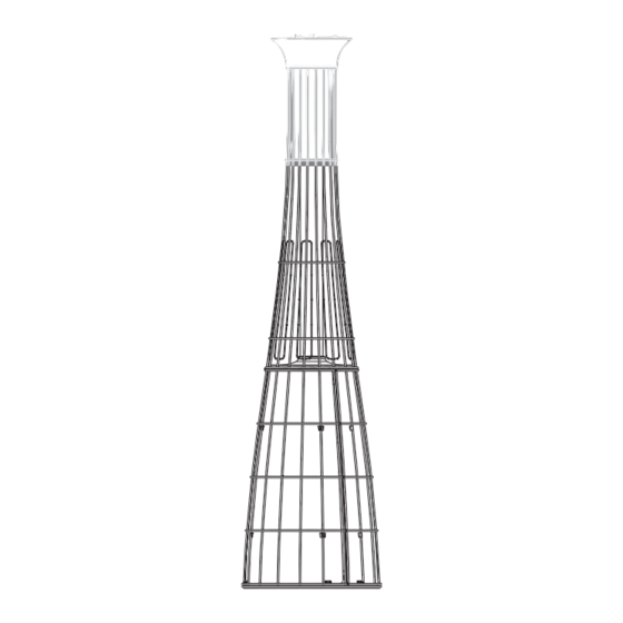
- Page 3 KEY: 1) fastening knob, 2) cover dish, 3) exchanger head, 4) protection grid, 5) glass pipe, 6) magnet, 7) bur- ner, 8) ignition/adjustment knob, 9) battery holder, 10) control unit (remote control Mod.), 11) tank support base, 12) side panel, 13) control cover panel, 14) trolley, 15) Antiwind, 16) SMALL remote control (remote control Mod.).
- Page 4 Fig.1 Fig.2...
- Page 5 Fig.4 1,5Volt 1,5Volt 1,5Volt torcia stilo ministilo Fig.5 Fig.6...
- Page 6 Fig.7 Fig.8 Fig.9...
- Page 7 Fig.10 Fig.11 Fig.12...
- Page 8 UK - REPLACING PIPE FRA - TUBE DE VERRE DE RECHANGE Fig.13 DE - ERSATZ TUBE NL - VERVANGING GLAZEN BUIS UK - TUBE MAINTENANCE FRA - TUBE EN VERRE PROPRE Fig.14 DE - WARTUNG TUBE NL - SCHONE GLAZEN BUIS optional...
- Page 9 Fig.15 centralina/control unit On MAX burner Off telecomando/remote control UK - DUNP-SWITCH SAFETY DEVICE Fig.16 DE - SAFETY DEVICE ANTI-KIPPEN FRA - ROULETTES ANTI-BASCULE NL - ANTITIPPER...
- Page 10 UK - TANK FIXING FRA - SERRURE A CYLINDRE Fig.17 DE - TANK HALTEBAND NL - SLOTCILINDER...
- Page 11 UK - With kit lights installed, the appliance must be covered and protected from the rain. Fig.18 DE - Bei Montage mit LED, müssen diese vor Regen geschützt werden. FRA - Avec le kit installé feux, placer l'appareil dans un endroit couvert et protégé de la pluie. NL - Met de kit geïnstalleerd lichten, plaatst u het apparaat in een afgedekt en beschermd tegen regen.
- Page 12 UK - KIT lights, battery and charger. Please read the information wrapping the charger and the instructions . - Do not use the charger in areas not covered or outside. - The battery (min 10 hours) is complete only when the green LED on the charger turns off. - Do not use the battery for more than 10 hours operation, this device requires a level Minimum charge for its pro- per operation and maintenance (about 200 charge cycles).
- Page 13 UK - ASSEMBLY EQUIPMENT FRA - MONTER LES APPAREILS Fig.19 DE - MONTIEREN SIE DEN APPARAT NL - MONTEER HET APPARAAT Fig.20 UK - ASSEMBLY COFFEE TABLE (Ø 80cm) FRA - ASSEMBLEZ LA TABLE (Ø 80cm) DE - AUFSPANNFLACHE (Ø 80cm) NL - MONTAGETAFEL (Ø...
- Page 14 Lightfire Dolce Vita SEEBECK Fig.21...
- Page 15 UK - Lightfire "Dolce Vita" with the SEEBECK effect IMPORTANT! This device requires no external power supply (mains or extra rechargeable battery). This model is equipped with a heat exchanger (1) in aluminum that, thanks to the effect thermoelectric Seebeck, converts the heat of the flame into electricity which is then used to power both the KIT LED lights that the gas valve.
- Page 16 DolceVita E.P. - serie 2 marrone / brown MODULI TERMICI bianco / white THERMAL MODULE rosso nero black SCHEDA ELETTRONICA ELECTRONIC BOARD grigio / grey BATTERIE BATTERY nero / black bianco / white marrone / brown marrone / brown nero rosso black rosso / red...
- Page 17 Tab. 1 Tab. 2...
-
Page 18: Table Of Contents
- UK - Contents THE REMOTE CONTROL GENERAL DESCRIPTION ASSEMBLY START-UP SWITCH-OFF MAINTENANCE STORAGE WARRANTY TROUBLESHOOTING... - Page 19 CAREFULLY LOOK AFTER THIS BOOKLET FOR THE ENTIRE LIFE OF THE APPLIANCE AND REQUEST A NEW ONE IN CASE OF DAMAGE OR LOSS! IMPORTANT! SHOULD THE PARTS BE DAMAGED, DO NOT GO AHEAD WITH ASSEMBLY! IMPORTANT! This appliance must be installed in compliance with the Regulations, Laws and Standards applicable in the Country of use.
-
Page 20: General Description
GENERAL DESCRIPTION Due to its specific type of operation with direct and reflected irradiance, this appliance approxi- mately heat up a surface of 13 m with a range of action of 2 meters. The weather of your spe- cific region could influence the device efficiency, as the appliance position (totally or in part open space) as your subjective heating feelings. - Page 21 ASSEMBLY OPERATIONS (MOBILE type with LPG tank): Before starting assembly operations, remove any guards. 1 – Delicately place the structure on the ground and fit the cover dish (Fig. 3: 2). 2 – Remove the side panels (Fig. 3) and position the tank on the base plate (Fig. 3: 11). 3 –...
-
Page 22: Start-Up
6 – Before making the connection, check to see whether the gas diaphragm (Fig. 9: 5) needs fitting on the inlet connection (Fig. 9: 4) (solution valid for SWITZERLAND, AUSTRIA, GER- MANY and LUXEMBOURG - see Tab. 1 or 2). IMPORTANT! DO NOT FIT the diaphragm on appliances fuelled with gas G30/G31 at 29÷37 mbar. - Page 23 IMPORTANT! WHEN FIRST STARTED – IN THE OPEN AIR OR WELL-VENTILATED ENVIRON- MENT – THE APPLIANCE COULD GIVE OFF VAPOURS OR SMELLS FOR A SHORT TIME. IMPORTANT! PLEASE AVOID USING THE OUTDOORS, ESPECIALLY IN ADVERSE WEATHER CONDITIONS. The technical characteristics of the glass tube are particular and such as to enable the resi- stance to thermal shock due to normal changes in temperature, humidity or light rain.
-
Page 24: Maintenance
SWITCHING OFF A - MANUAL mod.: 1 – Remove the side cover (Fig. 3: 13). 2 – Turn the control knob clockwise, returning this to position "0" (Fig. 5: 1). 3 – Correctly fit the side cover back on in reverse sequence. B –... -
Page 25: Storage
STORAGE If the appliance is not used for a long time (change of season or other reasons), follow the instructions below: - Store the appliance in a dry place, protected against any possible damage. - ALWAYS cover the burner unit and base to avoid obstructions (cobwebs, dust) or damage (denting, weather conditions, etc.). - Page 26 TROUBLESHOOTING: with remote control. FAULT CAUSE REMEDY 1-Not enough gas supply (bad LPG gasification 1-Clean, set / replace. No flame or dirt in system) or pressure regulator not set properly or faulty. 2-No gas flow (tank empty or interruption in 2-Check / replace.
- Page 27 TROUBLESHOOTING: manual controls. FAULT CAUSE REMEDY 1 – non enough gas supply flow: 1- Check: No flame - bad LPG gasification; - Check and replace empty tank; - bad LPG gasification with low temperature. - Replace with Propane gas tank. - pressure regulator wrongly set or faulty.
Need help?
Do you have a question about the lightfire dolce vita and is the answer not in the manual?
Questions and answers