
Summary of Contents for TOOLSMART TS04
-
Page 1: Digital Multimeter
DIGITAL MULTIMETER USER’S MANUAL TS04 99 Washington Street Melrose, MA 02176 Phone 781-665-1400 Toll Free 1-800-517-8431 Visit us at www.TestEquipmentDepot.com... -
Page 2: Table Of Contents
Checking Battery Voltage ..... . 13 Using the NCV Detector ......13 Using the Digital Multimeter with the ToolSmart ™... -
Page 3: Introduction
INTRODUCTION Thank you for purchasing General Tools & Instruments’ (General’s) TS04 ToolSmart ™ Digital Multimeter (DMM). Please read this user’s manual carefully and thoroughly before using the instrument. The DMM can be used as a standalone multimeter, or with General’s free ToolSmart ™... -
Page 4: Product Overview
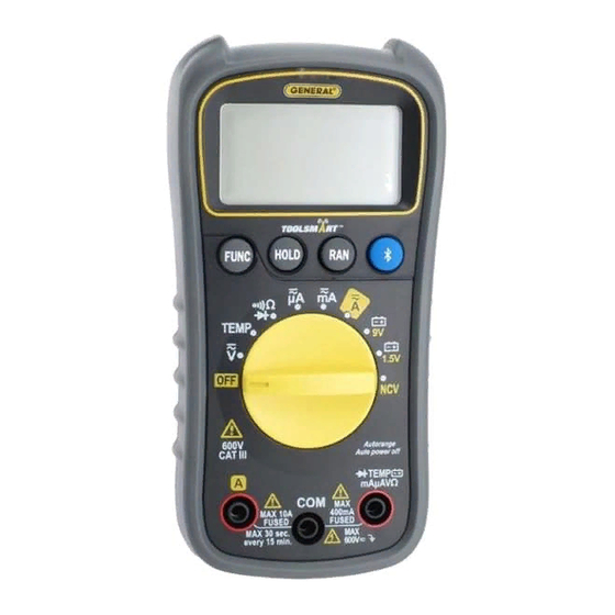
PRODUCT OVERVIEW Fig. 1 shows the labels and positions of the controls, LCD and physical structures of the meter. Fig. 2 shows all possible indications on the LCD. Familiarize yourself with the functions and meanings of all controls, indications and connectors before moving on to the safety, setup and operating instructions. 1. -
Page 5: Safety Instructions
1. Indicates DC voltage or current measurement 2. Indicates AC voltage or current measurement 3. Negative polarity indicator 4. Bluetooth enabled indicator 5. Indicates Auto power off function is enabled 6. Low battery indicator 7. Indicates detection of non- contact voltage 8. - Page 6 • •WARNING Do not apply more than the rated voltage, as marked on the TEMP meter, between the and COM jacks or between any jack and ground. mAµAVΩ Also do not input more than the rated current, as marked on the meter, through the A jack.
-
Page 7: Setup Instructions
Electrical Symbols Used On the Meter and In This Manual Symbol Description Symbol Description AC (Alternating Current) Fuse DC (Direct Current) Double-insulated Caution, risk of electric Risk of danger. Important shock. Hazardous voltage. information. Refer to the manual. Low battery indication Earth ground Diode Continuity beeper... -
Page 8: Operating Instructions
OPERATING INSTRUCTIONS GENERAL INSTRUCTIONS All parameters are measured through the included test leads. Unless you are measuring currents larger than 400 mA, plug the red test lead into the TEMP mAµAVΩ jack and the black test lead into the C OM jack. To measure currents larger than 400 mA, plug the red lead into the A jack (Fig. -
Page 9: Choosing A Measurement Range
DISABLING AUTO POWER OFF By default, the DMM will automatically power itself off following any period of 15 minutes of front-panel inactivity. The icon at the upper left of the LCD indicates that the Auto Power Off function is enabled. To disable the APO function, press and hold the FUNC button while powering on the meter by moving the rotary function switch to any position other than OFF. - Page 10 (1) Remove power from the circuit to be tested and discharge all high-voltage capacitors. (2) Turn the rotary switch to the , position,, depending on the µA amplitude of the current you expect to encounter. If you are unsure of the amplitude, select the 10A position first and then switch to the µA position if all of your measurements are less than 400mA.
-
Page 11: Measuring Resistance
MEASURING RESISTANCE •• •• Warning To avoid electrical shock or damage to the meter when measuring resistance, turn off all power to the circuit and discharge all high-voltage capacitors. Ω (1) Turn the rotary switch to the position and press the FUNC button until , k or M appears on the right side of the LCD. -
Page 12: Checking For Continuity
CHECKING FOR CONTINUITY •• •• Warning To avoid possible damage to the meter or other equipment, turn off the power source and discharge all high-voltage capacitors. Ω (1) Turn the rotary switch to the position and press the FUNC button until icon appears in the upper right corner of the LCD. -
Page 13: Checking Battery Voltage
APP AND AN APPLE iOS OR ANDROID SMARTPHONE To stream measurements and calculations made by the DMM to an Apple iOS or Android smartphone, begin by downloading the ToolSmart ™ app from the iTunes Store or Google Play Store to your mobile device. -
Page 14: Specifications
SPECIFICATIONS Parameter or Feature/Function Attribute Specification AC voltage Measurement ranges 0 to 4V/40V/400V/600V Measurement accuracy ±(1% of reading + 10 digits) Maximum resolution DC voltage Measurement ranges 0 to 400mV/4V/40V/400V/600V Measurement accuracy ±(0.8% of reading + 5 digits) in 600V range; ±(0.5% of reading + 2 digits) in other ranges Maximum resolution... -
Page 15: Specifications
Parameter or Feature/Function Attribute Specification Battery voltage Measurement ranges 0 to 9V, 0 to 1.5V Measurement ±(0.8% of reading + 7 digits) accuracy in 9V position; ±(3% of reading + 5 digits) in 1.5V position Max resolution Safety rating CAT III 600V NCV detection >110VAC voltage &... -
Page 16: Operating & Maintenance Tips
OPERATING & MAINTENANCE TIPS When the icon appears in the upper left corner of the LCD, immediately replace the meter’s “9V” battery by following the instructions on page 7. To replace a blown fuse: 1. Power off the meter. 2. Unplug the test leads. 3. -
Page 17: Warranty Information
WARRANTY INFORMATION General warrants its instruments and accessories, and digital tools products against defects in material or workmanship for one year from the date of purchase unless otherwise stated on the packaging, manual, and/or marketing materials. General also warrants its non-digital tools products against defects in material or workmanship on a limited lifetime term. -
Page 18: Fcc Statement
FCC STATEMENT This device complies with part 15 of the FCC Rules. Operation is subject to the following two conditions: (1) This device may not cause harmful interference, and (2) This device must accept any interference received, including interference that may cause undesired operation. This equipment has been tested and found to comply with the limits for a Class B digital device, pursuant to part 15 of the FCC Rules. - Page 19 NOTES __________________________________________________________ __________________________________________________________ __________________________________________________________ __________________________________________________________ __________________________________________________________ __________________________________________________________ __________________________________________________________ __________________________________________________________ __________________________________________________________ __________________________________________________________ __________________________________________________________ __________________________________________________________ __________________________________________________________ __________________________________________________________ __________________________________________________________ __________________________________________________________ __________________________________________________________...
-
Page 20: Washington Street
Melrose, MA 02176 Phone 781-665-1400 Toll Free 1-800-517-8431 Visit us at www.TestEquipmentDepot.com Specifications subject to change without notice ©2016 GENERAL TOOLS & INSTRUMENTS NOTICE - WE ARE NOT RESPONSIBLE FOR TYPOGRAPHICAL ERRORS. MAN# TS04 01/14/16 GeneralToolsNYC General Tools & Instruments...
Need help?
Do you have a question about the TS04 and is the answer not in the manual?
Questions and answers
Just purchased. Can I measure amps out of my solar panel?
Yes, the TOOLSMART TS04 can measure DC current (amps), which allows it to measure current from a solar panel. However, power must be turned off before connecting the meter to measure current.
This answer is automatically generated