Advertisement
Quick Links
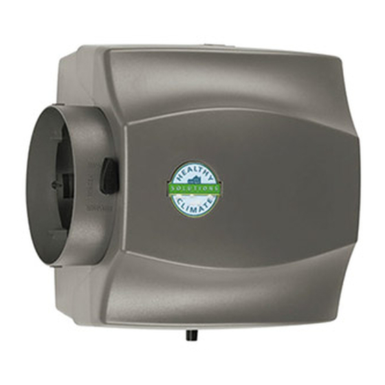
INSTALLATION INSTRUCTIONS AND TEMPLATE FOR HEALTHY CLIMATE LARGE BYPASS
HUMIDIFIER MODELS HCWB3-17, HCWB3-17K, HCWB3-17A & HCWB3-17AK
RE D COMPLETE S FETY INSTRUCTIONS
This product must be installed by a qualified heating and air conditioning contractor. Failure to do so could result in serious injury from electrical shock.
WARNING
1. ELECTRICAL SHOCK HAZARD.
Can cause injury or death.
Disconnect all electrical power
supplies before servicing.
2. RISK OF PROPERTY DAMAGE, INJURY OR
DEATH. Installation, adjustments, alterations,
service and maintenance must be performed
by your Lennox dealer.
3. RISK OF SCALDING. Water temperature over
125°F can cause severe burns and scalding
instantly. Shut off the hot water supply before
disconnecting or tapping into any hot water
supply line.
4. RISK OF SHARP EDGES HAZARD. Equipment
sharp edges can cause injuries. Avoid grasping
equipment edges without protective gloves.
RECOMMENDED WIRING DIAGRAMS
Models HCWB3-17A
NOTE
& HCWB3-17AK
VERIFY THAT MODE SWITCH
AUTOMATIC HUMIDIFIER CONTROL
IS IN THE "BYPASS" POSITION.
For detailed Automatic
Humidifier Control installation
NOTE
and wiring instructions, see
DO NOT WIRE TRANSFORMER
Publication No. 504,879M
USING FURNACE BLOWER CIRCUIT.
included with Control.
24 VAC FURNACE ACCESSORY TERMINALS
(10 VA MINIMUM) OR 24 VAC TRANSFORMER
Model HCWB3-17 & HCWB3-17K
MANUAL CONTROL
For detailed Manual Humidifier Control installation
and wiring instructions, see Publication No. 506407−01
included with Control.
IMPORTANT
USE 120 VAC POWER SOURCE OTHER THAN FURNACE MOTOR
CIRCUIT. HOWEVER, THE TRANSFORMER CAN BE POWERED OFF
THE HOT 120 VAC LINE BEFORE IT ENTERS THE FURNACE.
• DO NOT WIRE TRANSFORMER INTO FURNACE BLOWER CIRCUIT.
IMPORTANT
WHEN CURRENT SENSING RELAY IS USED:
• WIRE CURRENT SENSING RELAY INTO 24 VAC HUMIDIFIER
CONTROL CIRCUIT ONLY! DO NOT INSTALL IN TRANSFORMER
PRIMARY CIRCUIT.
HUMIDIFIER
506366-01
4/2011
(Supersedes 7/2009)
ATTENTION INSTALLER:
This product must be installed in compliance with all local, state and federal codes.
RISK OF PROPERTY AND EQUIPMENT DAMAGE.
1. Water heating system can be damaged if water
supply remains off.
2. After humidifier installation is completed, turn hot
water supply back on.
3. Water heating system must be de-energized if the
main water supply remains shut off.
4. Do not set humidity level above recommended or to
recommended level if condensation exists on inside
windows of any unheated space, as condensation
damage may result. Excess humidity can cause
moisture accumulation which can allow the
possibility for mold growth in your home.
5. Do not install humidifier in location where freezing
temperatures may occur. The water line could freeze
and crack causing water damage to the home.
R
C
H
24V
(10 VA MINIMUM)
SHUT-OFF
(SADDLE VALVE)
WATER SUPPLY
YELLOW
NOTE
24 V
SOLENOID
CURRENT SENSING RELAY
VALVE
REQUIRED IF TRANFORMER
WIRES
IS CONSTANTLY POWERED.
CONNECT DRAIN LINE HERE
SHUT-OFF
(SADDLE VALVE)
WATER SUPPLY
CONNECT DRAIN LINE HERE
TEMPL TE MUST BE LEVEL
TRACE ALONG OUTER EDGE
HEALTHY CLIMATE
ND INST LL TION TEMPL TE BEFORE ST RTING
CAUTION
6. Do not install humidifier or bypass connection
on furnace cabinet.
7. Do not install humidifier or bypass connection
on blanked off end of cooling coil where
airflow will be restricted.
8. Do not connect the transformer to blower
motor wiring. Premature component failure
may result.
9. Do not install humidifier where water
pressures exceed 125 psi, since humidifier
damage may result. Follow codes in effect
concerning pressure reduction.
10. Do not install humidifier on systems with
greater than 0.4 in. wg pressure differential
between supply and return plenums.
AUTOMATIC
HUMIDIFIER
ODT
CONTROL
CURRENT
SENSING
RELAY
COMMON
(IF REQUIRED)
MOTOR
LEAD
C
LO
HI
FURNACE
BLOWER MOTOR
MANUAL
HUMIDIFIER CONTROL
24 VAC FURNACE
ACCESSORY TERMINALS
YELLOW 24 V
OR TRANSFORMER
SOLENOID
(10 VA MINUMUM)
VALVE WIRES
CURRENT SENSING RELAY
FURNACE
(IF REQUIRED)
BLOWER MOTOR
C
HI
COMMON LEAD
LO
®
HUMIDIFIERS
SPECIFICATIONS
HUMIDIFIER DIMENSIONS
Width
(including solenoid valve):
Height
BYPASS DUCT OPENING
24 VAC-60 Hz, 0.5 AMP
INSTALLATION OPTIONS
The humidifier can be installed on either the
supply or return plenum of a forced air
handling system and is easily reversible for
NORTH, EAST
installation with right hand or left hand
OR WEST SIDE
bypass duct connections. The humidifier
OF HOME
dimensions and serviceability must be
OUTDOOR
considered when selecting the best location
TEMPERATURE
for the humidifier. Here are 2 examples of
SENSOR
many types of installations.
ABOVE EXPECTED
Upflow
SNOW LINE
FLUE
RETURN
AIR
90-1478
Horizontal
RETURN
AIR
90-1452
WARNING
Cover on humidifier must be securely in
place when blower is operating. Gas fumes,
90-1433
which could contain carbon monoxide, can
be drawn into living space resulting in
personal injury or death.
15
3
⁄
"
8
15
3
⁄
"
(including drain spud):
4
Depth
10
1
⁄
"
:
4
6" diameter
PLENUM OPENING
10"W x 12
3
⁄
"H
4
WATER FEED RATE
3 gph
ELECTRICAL DATA
SUPPLY
AIR
COOLING
COIL
COOLING
COIL
SUPPLY
AIR
Advertisement

Summary of Contents for Healthy Climate Solutions HCWB3-17
-
Page 1: Specifications
HUMIDIFIERS 4/2011 (Supersedes 7/2009) INSTALLATION INSTRUCTIONS AND TEMPLATE FOR HEALTHY CLIMATE LARGE BYPASS HUMIDIFIER MODELS HCWB3-17, HCWB3-17K, HCWB3-17A & HCWB3-17AK RE D COMPLETE S FETY INSTRUCTIONS ND INST LL TION TEMPL TE BEFORE ST RTING ATTENTION INSTALLER: This product must be installed by a qualified heating and air conditioning contractor. Failure to do so could result in serious injury from electrical shock. - Page 2 ⁄ ” I.D. plastic hose (not prevent sagging. Seal duct INSTRUCTIONS FOR HCWB3-17 & HCWB3-17K: The enclosed and bottom of the cover (1) 24 VAC. In order for the humidifier furnished). Run drain line from seams and humidifier base Manual Humidifier Control is designed for low voltage service to and base (2).


