Table of Contents
Advertisement
Quick Links
www.gigatronics.com
Publication 31231, Rev. J, October 2003
Giga-tronics Incorporated v 4650 Norris Canyon Road, San Ramon, CA 94583
925.328.4650/800.726.4442/925.328.4700 (Fax) v Customer Service: 800.444.2878/925.328.4702 (Fax)
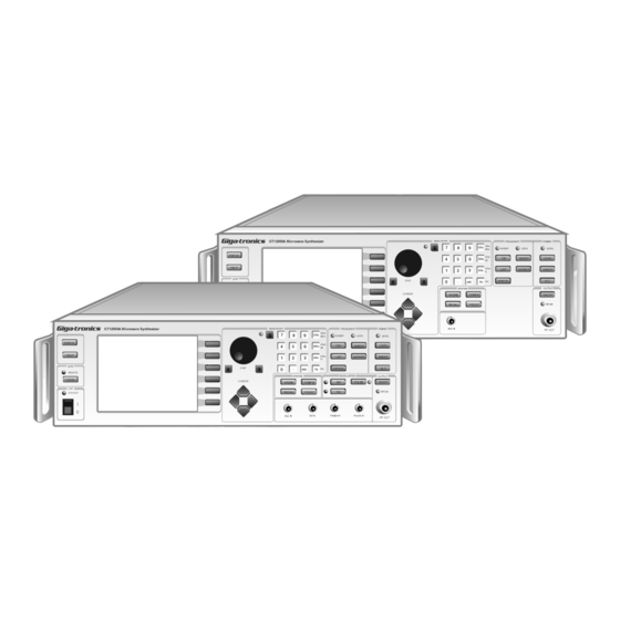
Series 12000A Microwave Synthesizers
Operation Manual
Certified Product
ISO 9001
Certified Process
Advertisement
Table of Contents

Subscribe to Our Youtube Channel
Related Manuals for Giga-tronics Series 12000A

Summary of Contents for Giga-tronics Series 12000A
- Page 1 Series 12000A Microwave Synthesizers Operation Manual Publication 31231, Rev. J, October 2003 Certified Product ISO 9001 Giga-tronics Incorporated v 4650 Norris Canyon Road, San Ramon, CA 94583 925.328.4650/800.726.4442/925.328.4700 (Fax) v Customer Service: 800.444.2878/925.328.4702 (Fax) Certified Process...
- Page 2 MODEL NUMBERS The Series 12000A has model numbers for each instrument with a specific frequency range as described in Chapter 1. All models are referred to in this manual by the general term 12000A, except where it is necessary to...
- Page 3 DECLARATION OF CONFORMITY...
-
Page 5: Table Of Contents
Contents About this Publication ..........................xi Conventions ..............................xiii Configuration Data .............................xv Record of Publication Changes ......................... xvii Special Configurations ..........................xix Introduction General Information ........................1-1 1.1.1 Introduction ......................1-1 1.1.2 Features ......................1-2 1.1.3 Environmental Standards ................... 1-2 1.1.4 Items Furnished ....................1-2 1.1.5 Items Required .................... - Page 6 Internally Generated Scan/AM Envelope........1-37 1.8.2.4 Power..................1-37 Front Panel Operation Introduction ..........................2-1 Front Panel Description ......................2-1 2.2.1 Series 12000A Front Panel Layout Descriptions ..........2-3 Front Panel Applications ......................2-9 2.3.1 Direct Entry .......................2-11 2.3.1.1 Numeric Keypad Entry..............2-11 2.3.1.2 Increment/Decrement ..............
- Page 7 Preface 2.3.5.4 Trigger Types................2-20 2.3.5.5 Configuring Points ..............2-20 2.3.5.6 Edit List ..................2-21 2.3.6 List Entry Speed Up ..................2-23 2.3.7 List Execution Speed Up .................. 2-23 2.3.7.1 Lists Precompilation..............2-23 2.3.7.2 Multiple Precompiled Lists ............2-23 2.3.7.3 Individual Point Execution Speed Up (Fast Option)....
- Page 8 Series 12000A Microwave Synthesizers 3.2.3.10 TRIGger Subsystem Commands..........3-28 3.2.4 SCPI Status Commands .................. 3-29 3.2.5 Sample SCPI Commands ................3-31 Native Command Codes ......................3-32 3.3.1 IEEE 488 Interface ................... 3-33 3.3.2 Command Syntax ..................... 3-33 3.3.2.1 Function Codes................3-33 3.3.2.2...
- Page 9 Preface Calibration ..........................4-9 4.3.1 Equipment & Documentation Required .............. 4-9 4.3.1.1 All Models ..................4-9 4.3.1.2 Additional Requirements (Series 125XXA/127XXA Only) ..4-10 4.3.2 Timebase Calibration ..................4-10 4.3.3 Output Amplitude Calibration ................4-10 4.3.3.1 Power vs. Detector Voltage ............4-10 4.3.3.2 Modulator Control vs.
- Page 10 Option 24: Internal Modulation Generator............A-3 A.3.5 Option 26: Step Attenuator (20 GHz Instruments) ..........A-4 A.3.6 Option 29: Scan Modulation................. A-4 Index Series 12000A Microwave Synthesizers .....................Index-1 Firmware Field Upgrade Introduction ..........................B-1 Series 12000A Firmware Upgrade Procedure ................B-1 Publication 31231, Rev. J, October 2003...
- Page 11 Preface Publication 31231, Rev. J, October 2003...
- Page 12 Series 12000A Microwave Synthesizers Illustrations Figure 1-1: Series 12000A Front Panel Inputs/Outputs (All Models) ..........1-5 Figure 1-2: Series 12000A Rear Panel Inputs/Outputs (All Models)..........1-6 Figure 1-3: Fuse Holder ....................... 1-10 Figure 2-1: Series 12000A Front Panel Layouts ................2-2 Figure 2-2: Display Screen with Interactive Softkeys..............
- Page 13 Table 1-1: Series 12000A Model Numbers.................. 1-1 Table 1-2: Series 12000A I/O Connector Descriptions ..............1-7 Table 1-3: Series 12000A IEEE 488.2 Hardware Configurations ..........1-8 Table 1-4: EIA-232 Pin Assignments ................... 1-9 Table 2-1: Phase Shift Completion Times ................. 2-13 Table 2-2: Factory Default Settings ...................
- Page 14 Series 12000A Microwave Synthesizers Publication 31231, Rev. J, October 2003...
-
Page 15: About This Publication
About this Publication This publication describes the local (front panel) and remote (GPIB) operation of the Giga-tronics Series 12000A Microwave Synthesizers: Preface In addition to a comprehensive Table of Contents and general information about the publication, the Preface also contains a record of changes made to the publication since its production, and a description of Special Configurations. - Page 16 Series 12000A Microwave Synthesizers Index - Series 12000A Microwave Synthesizers A subject listing of contents for the Series 12000A. Changes that occur after production of this publication, and Special Configuration data will be inserted as loose pages in the publication binder. Please insert and/or replace the indicated pages as detailed in the Technical Publication Change Instructions included with new and/or replacement pages.
-
Page 17: Conventions
Conventions The following conventions are used in this publication. Additional conventions not included here will be defined at the time of usage. Warning WARNING WARNING The WARNING statement is encased in gray and centered in the page. This calls attention to a situation, or an operating or maintenance procedure, or practice, which if not strictly corrected or observed, could result in injury or death of personnel. - Page 18 Series 12000A Microwave Synthesizers Publication 31231, Rev. J, October 2003...
-
Page 19: Configuration Data
Each instrument has a two-digit number. This number is the Manufacturing Configuration Code. Model Number Each instrument has a 5-digit serial number and one suffix character which designates the Series 12000A. Suffix character A is the Series version. Model Type (124XXA) CW, No Modulation (125XXA) Step (127XXA) Step &... - Page 20 Series 12000A Microwave Synthesizers Publication 31231, Rev. J, October 2003...
-
Page 21: Record Of Publication Changes
Record of Publication Changes This table is provided for your convenience to maintain a permanent record of publication change data. Replacement pages will be issued as a TPCI (Technical Publication Change Instructions), and will be inserted at the front of the binder. Remove the corresponding old pages, insert the new pages, and record the changes here. - Page 22 Series 12000A Microwave Synthesizers xviii Publication 31231, Rev. J, October 2003...
-
Page 23: Special Configurations
Special Configurations When the accompanying product has been configured for user-specific application(s), supplemental pages will be inserted at the front of the publication binder. Remove the indicated page(s) and replace it (them) with the furnished Special Configuration supplemental page(s). Publication 31231, Rev. J, October 2003... - Page 24 Series 12000A Microwave Synthesizers Publication 31231, Rev. J, October 2003...
-
Page 25: Introduction
1.1.1 Introduction The Series 12000A are Microwave Synthesizers with Step, Ramp (Series 127XXA Only) and List Sweep capability; the instruments operate over a wide range of microwave frequencies, power levels and in a variety of modulation modes. The 12000A can generate output signals over a frequency range of 10 MHz to 20 GHz;... -
Page 26: Features
Power Cord, 6 ft. (P/N WMPO-030007) 1.1.5 Items Required No special tools are required to operate the Series 12000A. Test equipment required for performance verification is described in Chapter 4 for the Series 124XXA and Section 4.4 for the Series 125XXA/ 127XXA within. -
Page 27: Cooling
FRAGILE — DELICATE INSTRUMENT If corresponding with the factory or the local Giga-tronics sales office regarding reshipment, please provide the model and serial number. If the instrument is being returned for repair, be sure to enclose all relevant information regarding the problem that has been found. -
Page 28: Installation
All instruments are shipped in operational condition and no special installation procedures are required. See Chapter 4 for warm-up time prior to calibration and testing for all models. Each Giga-tronics instrument must pass rigorous inspections and tests prior to shipment. Following installation, the performance of all models should be checked immediately to insure that operation has not been impaired during shipment. -
Page 29: I/O Connectors (Front Panel)
Introduction 1.3.1 I/O Connectors (Front Panel) Figure 1-1 illustrates the panel interface located on the front of the Series 12000A for all models. All connectors are type BNC unless otherwise stated. GT12000A Microwave Synthesizer DATA ENTRY FREQUENCY POWER nSec SWEEP... -
Page 30: I/O Connectors (Rear Panel)
I/O Connectors (Rear Panel) This section defines the panel interface and its functions located on the rear of the Series 12000A for all models. Some connectors are duplicates of the front panel for all models (See Figure 1-1 for reference). -
Page 31: Table 1-2: Series 12000A I/O Connector Descriptions
Introduction Table 1-2: Series 12000A I/O Connector Descriptions Model I/O Connector Connector Description 125XXA/ (Rear) 124XXA (Front) 127XXA ≥ Connector accepts a sweep or step trigger input √ √ TRIGGER IN ns wide at TTL level to initiate a sweep or step. -
Page 32: Computer Interface
1.3.3.1 GPIB The IEEE 488.2 interface connection (24-pin) between the Series 12000A and host computer equipment for remote operation over the General Purpose Interface Bus (GPIB) is located on the rear of the unit. The connector pin assignments are listed in Table 1-3 for all models. -
Page 33: Table 1-4: Eia-232 Pin Assignments
Introduction 1.3.3.2 EIA-232 This 9-pin connector interfaces communications equipment using RS-232 format. See the table below for the connector pin assignments to all models. Table 1-4: EIA-232 Pin Assignments Function Protective Ground Transmitted Data Received Data Request To Send Clear To Send Data Set Ready Signal Ground Carrier Detect... -
Page 34: Power
1.3.4 Power All models of the Series 12000A contains primary and stand by power with interval switching. The instrument automatically senses input line voltage in the range of 90 to 253 Vac, 47 to 64 Hz (400 Hz Optional). There are no manual voltage adjustments or selection controls. The 12000A has a 3-Wire power cord with a 3-terminal polarized plug for connection to the power source and safety ground. -
Page 35: Specifications
1.4.3 - Spectral Purity √ √ 1.4.4 - Step Frequency Sweep √ √ 1.4.5 - Step Power Sweep The following are specifications for the Series 12000A Microwave Synthesizers. 1.4.1 CW Operation Ranges Model 10 MHz to 8 GHz 12408A 12508A... - Page 36 Series 12000A Microwave Synthesizers Residual FM During Switching Refer to FM Table, Wide Mode Residual Column, Section 1.7.3 Phase Offset Mode Range -180 to +180 degrees Resolution .01 degrees, maximum Step Size .01 to 180 degrees Accuracy Not specified. This is relative mode of operation and is designed to be used interactively 1-12 Publication 31231, Rev.
-
Page 37: Rf Output
Introduction 1.4.2 RF Output Maximum Leveled Output (0 to 35 ° Frequency Range (GHz) Output Power (dBm) Option 26 (dBm) 0.01 to 2 +15 dBm +14 dBm >2 to <8 +15 dBm +15 dBm 8 to 15 +15 dBm +13 dBm >15 to 20 +15 dBm +12 dBm... - Page 38 Series 12000A Microwave Synthesizers Output SWR <2.0:1 (Typical) Level Drift <0.05 dB/hour. Max 0.1 dB/24 hours 1-14 Publication 31231, Rev. J, October 2003...
-
Page 39: Spectral Purity
Introduction 1.4.3 Spectral Purity Harmonics Frequency (GHz) Harmonic (dBc) Power (dBm) 0.01 to 0.10 0.10 to 2 >2 to 20 Subharmonics None, 0.01 - 2 GHz 0.01 - 2 GHz 55 dBc >2 GHz A subharmonic is defined as any ¼, ½, or ¾ multiple of the fundamental RF Output Nonharmonics <-60 dBc from 0.01 to 16 GHz (offsets >300 Hz) <-55 dBc from >16 to 20 GHz (offsets >300 Hz) -
Page 40: Step Frequency Sweep
Series 12000A Microwave Synthesizers 1.4.4 Step Frequency Sweep Range FA (minimum frequency of instrument) to FB (maximum frequency of instrument) Step Size Any increment within the frequency resolution Dwell Time May be set in 1 µs increments from approximately 1µs to 200 sec Setup Time 200 µs (Typical) -
Page 41: Step Power Sweep
Introduction 1.4.5 Step Power Sweep Range LA (minimum level of instrument) to LB (maximum level of instrument) Step Size Any increment within the instrument’s resolution Dwell Time May be set in 1 µs increments from approximately 1 µs to 200 sec Setup Time 100 µs (Typical) Accuracy &... -
Page 42: Supplemental Specifications
Series 12000A Microwave Synthesizers Supplemental Specifications Model Supplemental Specifications 125XXA/ 124XXA 127XXA √ √ 1.5.1 - General Specifications 1.5.2 - Weight & Dimensions √ √ √ √ 1.5.3 - Option 20 Specifications 1.5.1 General Specifications GPIB IEEE STD 488.2 (GPIB), all parameters except AC power on/off... -
Page 43: Option 20 (High Power) Specifications
Introduction 1.5.3 Option 20 (High Power) Specifications (Apply from 0× to 35×C) Output Power +20 dBm Flatness +/- 2.5 dB Harmonics <-5 dBc from 0.01 to 0.1 GHz <-20 dBc for 0.1 to 20.0 GHz @ +20 dBm Output Power Pulse On/Off (PULSE ON/OFF ONLY ON SERIES 12500A/12700A) 60 dBc... -
Page 44: Specifications (Series 12500A/12700A)
0.1 Hz Standard (1 kHz, Option 36) Minimum Sweep Width 100 Hz Standard (1 MHz, Option 36) Maximum Step Width From the minimum frequency to the maximum. Frequency of the Series 12000A as configured Sweep Width Resolution 0.1 Hz standard (1 kHz, Option 36) Sweep Time... - Page 45 Introduction O to 10 V Ramp Output Vout = (10 V) |(fout - fstart)| / |(fstop - fstart)|(Frequency Ramp sweep mode) Vout = (10 V) |(Pout - Pstart)| / |(Pstop - Pstart)|(Power Ramp sweep mode) Vout = 0 to 10 V ramp @ current set sweep rate (Ramp during CW mode) O.5 / GHz Output Vout = (0.5 V) (Fout in GHz) Sweep Modes...
-
Page 46: Ramp Power Sweep
Series 12000A Microwave Synthesizers 1.6.2 Ramp Power Sweep Continuous sweep, self generated within the instrument. Can be operated simultaneously with digital frequency sweep. Range - 10 dBm to maximum power, up or down (-120 dBm is maximum power with Option 26) Sweep Time (Any Sweep Mode) 2 ms to 200 sec in five ranges. -
Page 47: Modulation Parameters & Operational Modes
Introduction Modulation Parameters & Operational Modes Model Modulation Parameters & Operational Modes 125XXA/ 124XXA 127XXA √ 1.7.1 - Amplitude Modulation (AM) √ 1.7.2 - Scan Modulation √ 1.7.3 - Frequency Modulation (FM) √ 1.7.4 - Phase Modulation (φM) √ 1.7.5 - Pulse/Square Wave Modulation (PM) AM, FM, Pulse and Option 29 (Scan Modulation) driven by external waveforms is standard only on the 125XXA/127XXA models. -
Page 48: Externally Supplied Am Envelope
Series 12000A Microwave Synthesizers 1.7.1.2 Externally Supplied AM Envelope Waveform Any waveform compatible with bandwidth considerations Scaling 0%/V to 95%/V Input Voltage Minimum: -1 V, Maximum: +1 V for 50% depth ±10% depth @ 1 kHz modulation rate Input Impedance 600 Ω... -
Page 49: Frequency Modulation (Fm)
Introduction 1.7.3 Frequency Modulation (FM) Specifications apply with Scan/AM and PM off. FM may be operated simultaneously with Linear AM and or PM (PM & Linear AM not allowed simultaneously). 1.7.3.1 Wide Mode Envelope Parameters Maximum Deviation See table contained in Section 1.7.3.2 Minimum Deviation 10 kHz at 4 - 8 GHz (Other ranges proportionally) Modulation Resolution... -
Page 50: Narrow Mode Envelope Parameters
Series 12000A Microwave Synthesizers 1.7.3.2 Narrow Mode Envelope Parameters Maximum Deviation See table below Modulation Resolution 10 Hz (Deviation <10 kHz) 1 kHz (Deviation >10 kHz) (at 4 - 8 GHz, other ranges proportional) Flatness ±2 dB for rates from DC to 1 MHz (measured at 1 V input, i.e. -
Page 51: Internally Generated Fm Envelope
Introduction 1.7.3.3 Internally Generated FM Envelope See Option 24 specifications in Section 1.8.1 1.7.3.4 Externally Supplied FM Envelope Waveform Any waveform compatible with bandwidth considerations Rate DC to 8 MHz Input Sensitivity, Settable for maximum Peak deviation (FM deviation control set to maximum) Input Impedance 50 W (Nominal) Publication 31231, Rev. -
Page 52: Phase Modulation (Fm)
Series 12000A Microwave Synthesizers 1.7.4 Phase Modulation (φM) Specifications apply with SCAN/AM and PM off. f M may be operated simultaneously with Linear AM and or PM (PM & Linear AM not allowed simultaneously). 1.7.4.1 Wide Mode Envelope Parameter Maximum Deviation See table contained in Section 1.7.4.2... -
Page 53: Internally Generated Pm Envelope
Introduction Modulation Accuracy ±5% (relative to FM) at max deviation, 100 kHz modulation rate Distortion <5% (±1 MHz deviation) Incidental AM <±0.2%/MHz of deviation Frequency (GHz) Max Wide Deviation Max Narrow Deviation .010 to .016 .40 radians .02 radians >.016 to .032 .80 radians .04 radians >.032 to .064... -
Page 54: Pulse/Square Wave Modulation (Pm)
Series 12000A Microwave Synthesizers 1.7.5 Pulse/Square Wave Modulation (PM) Specifications apply with Scan/AM and FM off. PM may be operated with FM. 1.7.5.1 PM Basic Operation On/Off Ratio > 80 MHz Rise Fall/Times: Rise Time Frequency Range <10 ns >500 MHz <50 ns... -
Page 55: Internally Generated Pm Envelope
Introduction Delivered Minimum Pulse Widths Minimum Width Frequency Range 20 ns >500 MHz 100 ns 64 to 500 MHz 1 ms <64 MHz 1.7.5.2 Internally Generated PM Envelope See Option 24 specifications in Section 1.8.1 1.7.5.3 Externally Generated PM Envelope (One Envelope produced by each pulse) Repetition Rate 5 Hz to 5 MHz, leveled... -
Page 56: Supplemental Specifications (Series 12500A/12700A)
Series 12000A Microwave Synthesizers Supplemental Specifications (Series 12500A/12700A) Model Supplemental Specifications (Series 12500A/12700A) 125XXA/ 124XXA 127XXA √ 1.8.1 - Option 24 Specifications √ 1.8.2 - Option 29 Specifications 1.8.1 Option 24 (Internal Modulation Generator) Specifications 1.8.1.1 Amplitude Modulation Source Waveform... -
Page 57: Frequency Modulation Source
Introduction 1.8.1.2 Frequency Modulation Source Waveform Sine, square, triangle, ramp (+ or -) Rate 0.01 Hz to 1 MHz, all waveforms Resolution 0.01 Hz Accuracy ±0.01 Hz ± Timebase Accuracy 1 % (Typical) FM Output , into 1 M W 1.8.1.3 Pulse Modulation Source Rate... -
Page 58: Pulse Start Variable Delay
Series 12000A Microwave Synthesizers 1.8.1.4 Pulse Start Variable Delay (Referenced to Sync Output) Range 0 to 1.67 seconds Resolution 10 ns Accuracy ±2.5% of setting or ±20 ns, whichever is greater Jitter ±0.01% of setting or ±100 ps, whichever is greater 1.8.1.5... -
Page 59: Pulse Modes
Introduction 1.8.1.6 Pulse Modes (Triggered, Gated, Delayed, Singlet, Doublet, Triplet, or Quadlet and Free Running) Interval Range 100 ns to 1.67 seconds Resolution 10 ns Accuracy ±2.5% of setting or 20 ns, whichever is greater Jitter 0.01% of setting or 100 ps, whichever is greater NOTE: The interval between pulse one and pulse two, and the interval between triplets and quadlets are the same. -
Page 60: Option 29 (Scan Modulation) Specifications
Series 12000A Microwave Synthesizers 1.8.2 Option 29 (Scan Modulation) Specifications Specifications apply with FM and PM turned off. 1.8.2.1 Envelope Parameters Frequency of Operation 0.01 to 20 GHz 1.8.2.2 Scan Mode Range 0 to 60 dB, ≥ +10 dBm (Settable to 65 dB) Resolution 0.1 dB... -
Page 61: Internally Generated Scan/Am Envelope
Introduction 1.8.2.3 Internally Generated Scan/AM Envelope See Specifications for Option 24 in section 1.8.1 1.8.2.4 Power 2 dB reduction in power, .01-20 GHz Publication 31231, Rev. J, October 2003 1-37... - Page 62 Series 12000A Microwave Synthesizers 1-38 Publication 31231, Rev. J, October 2003...
-
Page 63: Front Panel Operation
√ 2.2.1 - Series 12000A Front Panel Layout Descriptions The Series 12000A front panel contains the controls and display for complete local operation of the instrument. Front panel controls are grouped according to functions performed. Descriptions of the controls are referenced to the blocked numbers illustrated in Figure 2-1 on the next page for all models. -
Page 64: Series 12000A Front Panel Layouts
Series 12000A Microwave Synthesizers Figure 2-1: Series 12000A Front Panel Layouts Publication 31231, Rev. J, October 2003... -
Page 65: Series 12000A Front Panel Layout Descriptions
Front Panel Operation 2.2.1 Series 12000A Front Panel Layout Descriptions Power When this power switch is turned ON, the adjacent LED will be green. When the power switch is OFF but main power is connected on the rear panel, the LED will be yellow to indicate a standby condition. -
Page 66: Data Entry Field (All Models)
Series 12000A Microwave Synthesizers Data Entry Field The DATA ENTRY field contains the 12-button keypad, Units keys, Knob Lock key, CURSOR keys, and the resolution STEP Up/Down keys and adjusting knob. Figure 2-3 illustrates the Data Entry field. Each control within the field is explained in the following paragraphs. - Page 67 Front Panel Operation Step Keys These keys increment or decrement a parameter value by one each time they are pressed. The keys duplicate the action of the adjusting knob except that they always step the value up or down by one.
- Page 68 Series 12000A Microwave Synthesizers Power Field This field controls the parameters for power level and sweep operation. Level Press [LEVEL] to adjust the output signal level. Sweep Press [SWEEP] to configure a power sweep and to select alternate sweep methods. The sweep parameters can be changed while this menu is displayed.
-
Page 69: System Configuration Selection (Preset)
Front Panel Operation Figure 2-4: System Configuration Selection (Preset) Modulation Field The MODULATION field selects the type of modulation to be used. AM, FM, φM and PM are available (SERIES 125XXA/127XXA ONLY). Press [AM] to select amplitude modulation. AM can be linear, expressed in percent, or Scan (Option 29), expressed in dB with the output power being proportional to the input voltage. - Page 70 Series 12000A Microwave Synthesizers RF Field The RF field provides an RF connector and a switch to turn the output on and off. The adjacent LED will be ON when the RF output is turned on. The front panel RF connector will be relocated to the rear panel when Option 22 is installed.
-
Page 71: Front Panel Applications
Front Panel Operation Front Panel Applications Model Front Panel Applications Page 125XXA/ 124XXA 127XXA √ √ 2.3.1 - Direct Entry 2-11 √ √ 2.3.2 - Set a CW Signal 2-12 √ √ 2.3.3 - Step Frequency Sweep Configuration 2-15 √ √... - Page 72 Series 12000A Microwave Synthesizers The 12000A features a comprehensive HELP system linked to the current display. Press the [HELP] key to display general information about the function — this screen also provides softkeys selections for more detailed help topics. 2-10...
-
Page 73: Direct Entry
Front Panel Operation 2.3.1 Direct Entry Data Entry for the various menus depends on the type of entry. Parameters with numeric values can be entered and changed by the following methods: 2.3.1.1 Numeric Keypad Entry With the cursor positioned at the far left (e.g., on FREQ in the Fixed Frequency menu as shown in Figure 2-5), enter the numeric value with the keypad. -
Page 74: Set A Cw Signal
Series 12000A Microwave Synthesizers 2.3.2 Set a CW Signal [CW] [LEVEL] [CW] Press to generate a fixed frequency at a fixed amplitude. Pressing will select the [LEVEL] Frequency field and pressing will select the Power Level field. The up and down cursor can be used to one field or the other in either menu. -
Page 75: Change Output Phase
Front Panel Operation 2.3.2.2 Change Output Phase The Phase Change menu is accessed via a softkey from the CW menu. Figure 2-6: Phase Adjustment Selection Figure 2-7: Phase Adjustment Selection (Phase Change) • The minimum and maximum values allowed are +/- 180.00 degrees •... -
Page 76: Change Resolution
Series 12000A Microwave Synthesizers Table 2-1: Phase Shift Completion Times Typical Time for Completion of Phase Shift CWFreq 11 MHz 11 MHz 50 MHz 500 MHz 1 GHz 2 GHz 2 GHz 4 GHz 4 GHz 8 GHz 16 GHz Φ... -
Page 77: Step Frequency Sweep Configuration
Front Panel Operation 2.3.3 Step Frequency Sweep Configuration Use this feature to set up a step frequency sweep. Figure 2-8 illustrates the Step Frequency Sweep menu. A Step Frequency Sweep will start and stop at the frequency values designated in the configuration. The dwell time and the output power at each step also need to be defined. -
Page 78: Step Frequency Sweep Parameters
Series 12000A Microwave Synthesizers 2.3.3.1 Step Frequency Sweep Parameters Sweep Type The sweep type is selective between Step and Ramp (Ramp is only available on Series 127XXA models). This section details how to set up a Step Frequency sweep; See Section 2.3.11 for instructions on how to set up a Ramp Frequency sweep. -
Page 79: Add Markers To A Frequency Sweep
Front Panel Operation 2.3.4 Add Markers to a Frequency Sweep Markers can be added to a sweep in different ways to identify their position in the sweep. Markers can be entered as video, intensity, or amplitude. Video markers illuminate the vertical reticule when the markers are reached. - Page 80 Series 12000A Microwave Synthesizers [Pause Time] 5. For intensity markers, adjust the pause time of the marker by pressing and using the keypad to set the new time. Press the appropriate [Units] key to activate the new value. The minimum value must be =>1.0 µ s See Section 2.3.2 for instructions on how to copy a frequency directly from the CW Frequency menu to...
-
Page 81: List Set Up
Front Panel Operation 2.3.5 List Set Up The List Mode is an alternate sweep method that takes full advantage of automatic switching at the highest sweep speed. To configure up to 99 lists with a variety of points in each, and then allow the instrument to automatically scan through the points. -
Page 82: List Table
Series 12000A Microwave Synthesizers 2.3.5.2 List Table Place the cursor on this parameter. Press the Step Up or Down key to increment or decrement the list number. Enter the list number with the keypad and press any Units key to complete the entry. Each table represents a different sweep configuration;... -
Page 83: Edit List
Front Panel Operation are best changed by entering the new value with the keypad and pressing the appropriate Units key. The values can then be fine-adjusted with either the Step keys or the adjusting knob. ☛ NOTE: Points do not have to be entered in any numerical or other order. They can be inserted in any order. - Page 84 Series 12000A Microwave Synthesizers To change range refer to Figure 2-12. Figure 2-12: List 1 Range Menu The list number will be displayed in the menu title at the top of the screen. To edit the range of a list...
-
Page 85: List Entry Speed Up
Lists Precompilation In the Series 12000A, list points exist in two different forms. One is the source form, where the data describing a point is in a form that closely corresponds to the human readable formats used by the front panel’s list menu. -
Page 86: Individual Point Execution Speed Up (Fast Option)
Series 12000A Microwave Synthesizers 2.3.7.3 Individual Point Execution Speed Up (Fast Option) While executing a list part of the operation of the CPU is dedicated to updating the display. There are options available to set the display certain ways such as blanking it or freezing it to relieve the CPU of this burden. -
Page 87: List Points Storage
Front Panel Operation 2.3.8 List Points Storage When a list is created the points are stored in “source” form and when a list is precompiled the point is stored in “object” form. Source form points are allocated from nonvolatile memory so that they will be preserved even when the unit is off and power is removed. -
Page 88: Cpu Busy Clock
Series 12000A Microwave Synthesizers 2.3.8.1 CPU Busy Clock This feature provides a visual indicator of when the CPU is busy (Figure 2-14). Figure 2-14: CPU Busy Clock Feature 2.3.8.2 Keyboard Abort This feature provides a method to abort any time consuming process that keeps the CPU busy. The keys able to abort a process are: •... -
Page 89: Step Power Sweep Configuration
Front Panel Operation 2.3.9 Step Power Sweep Configuration Use this feature to set up a step power sweep. Figure 2-15 illustrates the Step Power Sweep menu. A Step Power Sweep will start and stop at the power values designated in the configuration. The dwell time and the output frequency at each step also need to be defined. -
Page 90: Step Power Sweep Parameters
Series 12000A Microwave Synthesizers 2.3.9.1 Step Power Sweep Parameters Sweep Type The sweep type is selective between Step and Ramp (Ramp is only available on Series 127XXA models). This section details how to set up a Step Power sweep. See Section 2.3.12 for instructions on how to set up a Ramp Power sweep. -
Page 91: Alc Operation
Front Panel Operation 2.3.10 ALC Operation Figure 2-16: Automatic Leveling Control Selection The ALC menu screen allows controlling the various functions which relate to the setting of the instrument output power. Some of the modes are optional, a few are yet to be released. The descriptions following detail the operation 2.3.10.1 ALC Menu without Step Attenuator... -
Page 92: Alc Mode
Series 12000A Microwave Synthesizers 2.3.10.2 ALC Mode This field allows choosing between leveled power and maximum power. In the leveled power mode, the output power (modified by the Power Slope and/or Offset parameters) is set by the operator. When Maximum Power is selected, the instrument will produce the highest power possible. The Level LED remains on when in Maximum Power mode. -
Page 93: Offset
Front Panel Operation The ‘Slope Start Frequency’ field sets the point at which slope correction begins. The output power then changes at a rate set by the slope variable. The ‘Power Level’ field is for convenience in setting the global power level variable. Note the letters ‘SLP’, these appear in the any menu having a Level field to indicate that Power Slope is enabled. -
Page 94: Ramp Frequency Sweep Configuration (Series 12700A Only)
Series 12000A Microwave Synthesizers 2.3.11 Ramp Frequency Sweep Configuration (Series 12700A Only) Use this feature to set up a Ramp frequency sweep. Figure 2-19 illustrates the Ramp Frequency Sweep menu. A Ramp frequency sweep starts at a designated frequency and runs continuously until it reaches a stop frequency. -
Page 95: Ramp Frequency Sweep Parameters
Front Panel Operation 2.3.11.1 Ramp Frequency Sweep Parameters Sweep Type The sweep type is selective between Step and Ramp. This section details how to set up a Ramp Frequency sweep; See Section 2.3.3 for instructions on how to set up a Step Frequency sweep. With the cursor on Sweep type, press either Step key to select Ramp. -
Page 96: Ramp Power Sweep Configuration (Series 12700A Only)
Series 12000A Microwave Synthesizers 2.3.12 Ramp Power Sweep Configuration (Series 12700A Only) Use this feature to set up a Ramp Power sweep. Figure 2-20 illustrates the Ramp Power Sweep menu. A Ramp Power sweep starts at a power level, which must designated, and runs continuously until it reaches a stop level. -
Page 97: Ramp Power Sweep Parameters (Series 12700A Only)
Front Panel Operation 2.3.12.1 Ramp Power Sweep Parameters (Series 12700A Only) Sweep Type The sweep type is selective between Step and Ramp. This section details how to set up a Ramp sweep, See Section 2.3.3 for instructions on how to set up a Step sweep. With the cursor on Sweep Type, press either Step key to select Ramp. -
Page 98: External Amplitude Modulation (Series 12500A/12700A Only)
Series 12000A Microwave Synthesizers 2.3.13 External Amplitude Modulation (Series 12500A/12700A Only) Linear AM ☛ NOTE: Option 24 is available to provide internal AM, FM or PM and Option 29 is available to provide Scan AM (Logarithmic AM). [AM] Press to select the modulation parameter. Refer to the modulation parameters and specifications in Chapter 1 for detailed information. -
Page 99: Internal Amplitude Modulation (Series 12500A/12700A Only)
Front Panel Operation 2.3.14 Internal Amplitude Modulation (Series 12500A/12700A Only) [AM] Press to select the modulation parameter. Refer to the modulation parameters and specifications in Chapter 1 for detailed information. Figure 2-22: Amplitude Modulation Selection (Internal) When Option 24 is installed in the instrument, the Amplitude Modulation Screen appears as shown in Figure 2-22. - Page 100 Series 12000A Microwave Synthesizers Depth Since the amplitude of the internal source is calibrated (Typical for Gaussian noise), the modulation depth may be set directly from the menu. Modulation depth is expressed in % for linear AM and dB for SCAN (Logarithmic) AM.
-
Page 101: External Scan Amplitude Modulation (Opt. 29) (Series 12500A/12700A Only)
Front Panel Operation 2.3.15 External Scan Amplitude Modulation (Opt. 29) (Series 12500A/12700A Only) Scan AM (Logarithmic AM) [AM] Press to select the modulation parameter. Refer to the modulation parameters and specifications in Chapter 1 for detailed information. Using Scan Modulation Scan AM is defined as a logarithmic change in the RF output level for a linear change in the input voltage. - Page 102 Series 12000A Microwave Synthesizers Input Voltage The AM Input BNC connector Input Voltage for Scan Modulation (Logarithmic AM) is 0 to +6 Volts. 2-40 Publication 31231, Rev. J, October 2003...
-
Page 103: Internal Modulation (Opt. 24) With Scan Am (Opt. 29) Selected
Front Panel Operation 2.3.16 Internal Modulation (Opt. 24) with Scan AM (Opt. 29) Selected (Series 12500A/12700A Only) Scan AM (Logarithmic AM) [AM] Press to select the modulation parameter. Refer to the modulation parameters and specifications in Chapter 1 for detailed information. Figure 2-24: Scan AM (Internal) Using Internal Scan With AM Mode: highlighted (reference above screen), use the UP or DOWN Step Key to select Scan. -
Page 104: External Frequency Modulation (Series 12500A/12700A Only)
Series 12000A Microwave Synthesizers 2.3.17 External Frequency Modulation (Series 12500A/12700A Only) Wideband FM/Narrowband FM [FM] Press to select the modulation parameter. Refer to the modulation parameters and specifications in Chapter 1 for detailed information. Using Frequency Modulation There are four modes of operation for Frequency Modulation. - Page 105 Front Panel Operation Sensitivity This parameter selection allows the user to specify how much deviation is produced for a 1 volt input. The value is the peak deviation. 1 volt is the maximum permitted input level. If less than 1 volt is input, the deviation may be computed by multiplying the input voltage by the displayed deviation setting.
-
Page 106: Internal Frequency Modulation (Series 12500A/12700A Only)
Series 12000A Microwave Synthesizers 2.3.18 Internal Frequency Modulation (Series 12500A/12700A Only) [FM] Press to select the modulation parameter. Refer to the modulation parameters and specifications in Chapter 1 for detailed information. When Option 24 is installed in the instrument, the Frequency Modulation Screen appears as shown below. - Page 107 Front Panel Operation Deviation This parameter field allows setting the deviation for the frequency modulation. The deviation is set directly since the modulation generator output is a fixed level. The deviation limits are the same as with external modulation. The phase modulation menu is accessed by a softkey labeled “Switch to FM” in the FM menu (See figure on previous page).
-
Page 108: Phase Modulation (Series 12500A/12700A Only)
Series 12000A Microwave Synthesizers 2.3.19 Phase Modulation (Series 12500A/12700A Only) [FM] Press to select the modulation parameter. Refer to the modulation parameters and specifications in Chapter 1 for detailed information. Figure 2-27: Phase Modulation Selection Using Phase Modulation Phase modulation, as implemented in the Series 125XXA/127XXA, is created by simply differentiating the input modulating signal. -
Page 109: External Pulse Modulation (Series 12500A/12700A Only)
Front Panel Operation 2.3.20 External Pulse Modulation (Series 12500A/12700A Only) Active High (Positive-going)/Active Low (Negative-going) [PM] Press to select the modulation parameter. Refer to the modulation parameters and specifications in Chapter 1 for detailed information. Figure 2-28: Pulse Modulation Selection Using Pulse Modulation The Pulse Modulation function allows controlling the instrument RF output with a high speed high on/off ratio level shift (on/off keying). -
Page 110: Internal Pulse Modulation (Series 12500A/12700A Only)
Series 12000A Microwave Synthesizers 2.3.21 Internal Pulse Modulation (Series 12500A/12700A Only) [PM] Press to select the modulation parameter. Refer to the modulation parameters and specifications in Chapter 1 for detailed information. When Option 24 is installed in the instrument, the Pulse Modulation screen appears as shown below. in addition, the operation of the additional fields is described below. - Page 111 Front Panel Operation Waveform This parameter determines how many pulses are produced for each trigger (internal or external). The maximum number of pulses per group is four. Each pulse in the group will have the same width. The ‘Start Delay’ parameter will always be the time from the trigger to the first pulse in the group. See ‘Gap’, below for a description of the inter-pulse spacing.
-
Page 112: Interface Configuration
Series 12000A Microwave Synthesizers 2.3.22 Interface Configuration To configure the GPIB interface use the menu shown in Figure 2-30. To access the menu press the [CONFIG] GPIB key then press the softkey. GPIB Address This sets the GPIB address; the default is 6. -
Page 113: Network Analyzer Sweep Settings (Series 12700A Only)
The Ramp Frequency and Power Sweep Interface default is set to “Network Analyzer” to support Giga-tronics’ 8003 Precision Scalar Analyzer (See the left side graphic in Figure 2-32 below). The ramp sweeps are set to CONTINUOUS and IMMEDIATE by default. To go from “Network Analyzer” to “Normal”... -
Page 114: System Reset
A battery failure (The “Signature Failure” menu could appear) • Power interruption to the Series 12000A while NVRAM is being modified (In example, a List is being created) Resetting the checksum will allow in most cases for normal operation without losing current settings, stored setups or Lists. - Page 115 Front Panel Operation Signature Failure Menu The NVRAM also contains a 32 bit signature word. The signature word has two purposes: • Change in a new firmware forces the user to initialize NVRAM due to restructuring (Changing the arrangement of NVRAM without adding new information would not cause a “Checksum Failure” and a failure is forced) •...
-
Page 116: Table 2-2: Factory Default Settings
Series 12000A Microwave Synthesizers Table 2-2: Factory Default Settings Model Parameter Default Condition 125XXA/ 124XXA 127XXA √ √ CW Frequency Minimum √ √ RF @ Power up √ √ RF Level 0 dBm √ Amplitude Modulation √ AM Rate (Opt. 24) 1 kHz √... -
Page 117: Remote Operation
√ 3.1.1 - Languages Available The Series 12000A Microwave Synthesizers can be operated from a remote host over the General Purpose Interface Bus (GPIB) using either Standard Commands for Programmable Instruments (SCPI) or Native language commands. Operation via the RS-232 interface is possible using the Native commands for all three models. -
Page 118: Scpi Command Codes
3.2.4 - SCPI Status Commands √ √ 3.2.5 - Sample SCPI Commands The SCPI syntax implemented in the Series 12000A includes the IEEE 488.2 Common commands, status reporting, error reporting, and table-specified defaults at power-up or *RST. 3.2.1 SCPI Command Format Details of typography (such as indentation, case, and punctuation) are very significant in SCPI and must be attended to with great care. - Page 119 Remote Operation Some commands require a parameter. The parameter types are listed below for all three models: Boolean A Boolean (true or false) condition. Enter: ON or 1 for TRUE OFF or 0 for FALSE NUM_VAL A numeric value or a qualitative term which represents a numeric value. Enter: Sign (optional) value digits decimal point (optional)
-
Page 120: Scpi Mandated Commands
Series 12000A Microwave Synthesizers 3.2.2 SCPI Mandated Commands The following are SCPI mandated commands. The command syntax is followed by a description of the command. Many of these commands refer to the Status System, which is discussed in detail in Section 3.2.4. - Page 121 Remote Operation *OPC? Syntax: *OPC? Description: This query form places an ASCII character 1 into the device’s output queue when all pending selected device operations have been finished. Unlike the *OPC command, the *OPC? query does not affect the OPC Event bit in the Standard Event Status Register (ESR). *RST Syntax: *RST...
- Page 122 Series 12000A Microwave Synthesizers Syntax: Response: Returns a binary string containing the status bits of Lock, Level and Calibration. Description: This command ouputs a 16-bit binary format string as described in the following table. Bits Condition Not used - always 0...
-
Page 123: Scpi Source Commands
Remote Operation 3.2.3 SCPI SOURCe Commands SCPI Source commands are divided into the sections listed below. In some cases the Source code may contain additional sets of functions. All Source subsystem commands begin with [SOURce], but as [SOURce] is the default command at the root level it need not be entered. The following SOURce subsystems are used in the 12000A: Model SCPI SOURCe Commands... -
Page 124: Am Subsystem Commands (Series 12500A/12700A Only)
Series 12000A Microwave Synthesizers 3.2.3.1 AM Subsystem Commands (Series 12500A/12700A Only) The Amplitude Modulation subsystem sets the modulation controls and the parameters associated with the modulating signal(s). ■ AM:DEPTh ■ AM:INTernal:FUNCtion:SHAPe ■ AM:SCALing ■ AM:SCAN ■ AM:STATe ■ AM:SOURc:EXTernal ■... - Page 125 Remote Operation AM:SCAN Syntax: AM: SCAN n Example: AM: SCAN 2 ! Activates internal Scan Amplitude Modulation Description: Activate and select the source of the Scan AM according to the following values for n: n = 0 Deactivate (turn off) Scan Amplitude Modulation. n = 1 Activate external Scan Amplitude Modulation (Only with Option 29).
- Page 126 Series 12000A Microwave Synthesizers AM:TYPE Syntax: AM:TYPE <Boolean> Example: AM:TYPE LOGarithmic ! Select LOGarithmic AM shaping Description: This command controls the AM shaping. The default is LINear. LINear = The output voltage is directly proportional to V LOGarithmic = The output voltage is proportional to log (V...
-
Page 127: Fm Subsystem Commands (Series 12500A/12700A Only)
Remote Operation 3.2.3.2 FM Subsystem Commands (Series 12500A/12700A Only) The Frequency Modulation command subsystem sets the modulation controls and the parameters associated with the FM signal(s). The FM commands used in the 12000A are: ■ FM[:DEViation] ■ FM:INTernal:FUNCtion:SHAPe ■ FM:SENSitivity ■... - Page 128 Series 12000A Microwave Synthesizers FM:STATe Syntax: FM:STATe <Boolean> Example: FM:STATe ON (or OFF) ! Turn the FM output ON (or OFF) Description: This command activates or deactivates the FM mode. FM:TYPE Syntax: FM:TYPE Example: FM:TYPE ! Switch to another model Description: It sets the mode for Frequency Modulation.
-
Page 129: Frequency Subsystem Commands
Remote Operation 3.2.3.3 FREQuency Subsystem Commands The Frequency subsystem commands control the frequency sweep characteristics of the 12000A. This subsystem includes the following commands: ■ FREQuency[:CW|:FIXed] ■ FREQuency[:CW|:FIXed]? ■ FREQuency[:CW|:FIXed]:RES ■ FREQuency[:CW|:FIXed]:STEP ■ FREQuency[:CW|:FIXed]:STEP[:INCRement] ■ FREQuency[:CW|:FIXed]:STEP[:INCRement]? ■ FREQuency:CENTer ■ FREQuency:CENTer? ■... - Page 130 Series 12000A Microwave Synthesizers FREQuency[:CW|:FIXed]:STEP Syntax: FREQuency:STEP <Num_Val> [HZ | KZ | MZ | GZ] Example: FREQuency:STEP 100 HZ ! Set the sweep frequency step to 100 Hz Description: This command specifies a sweep frequency step size. The commands FREQuency[:CW] and FREQuency[:FIXed] are synonymous; either command specifies a fixed frequency for the synthesizer.
- Page 131 Remote Operation FREQuency:MODE Syntax: FREQuency:MODE CW|FIXed|SWEep|LIST|SENSe Example 1: FREQuency:MODE CW ! Set the CW commands to control the frequency subsystem Example 2: FREQuency:MODE LIST ! Set the List commands to control the frequency subsystem Description: This command establishes which set of commands will be used to control the frequency subsystem.
- Page 132 Series 12000A Microwave Synthesizers FREQuency:STOP Syntax: FREQuency:STOP <Num_Val> [HZ | KZ | MZ | GZ] Example: FREQuency:STOP 100 MZ ! Set the sweep stop frequency to 100 MHz Description: This command sets the STOP frequency. It also sets the upper limit of a manual sweep.
-
Page 133: List Subsystem Commands
Remote Operation 3.2.3.4 LIST Subsystem Commands ■ LIST:ADD:POINt ■ LIST:DELete:LIST ■ LIST:DELete:POINt ■ LIST:DWELl ■ LIST:DWELl:POINt ■ LIST:DWELl:POINt? ■ LIST:FREQuency ■ LIST:FREQuency:POINt ■ LIST:FREQuency:POINt? ■ LIST:PRECompute? ■ LIST:POWer ■ LIST:POWer:POINt ■ LIST:POWer:POINt? ■ LIST:RANGe:ADD ■ LIST:RANGe:DWELI ■ LIST:RANGe:POWer ■ LIST:RANGe:STARt ■... - Page 134 Series 12000A Microwave Synthesizers LIST:DELete:POINt Syntax: LIST:DELete:POINt n1 n2 Example: LIST:DELete:POINt 1 3 ! Deletes point 3 of list 1 Description: This command deletes point n2 from list n1. After a point is deleted, the following points in the list are promoted to replace the one deleted (NOTE: n2 = 1 denotes the first point in the list).
- Page 135 Remote Operation LIST:PRECompute? Syntax: LIST:PRECompute? n Example: LIST:PRECompute? 1 ! Performs precompute for list 1 Description: This command calculates list n, and stores the calculated values in RAM. Return 0 when done. When the pre-calculated list is subsequently run, the first trace will run at full speed, since the instrument will not need to do the calculations as part of executing the first trace.
- Page 136 Series 12000A Microwave Synthesizers LIST:RANGe:POWer Syntax: LIST:RANGe:POWer Example: LIST:RANGe:POWer -3 ! Set the list power range to -3 dBm Description: This command sets the power output for each point in the list range set to d (NOTE: The unit for the power level is dBm).
- Page 137 Remote Operation LIST:TRIGger:SOURce Syntax: LIST:TRIGger:SOURce BNC|GPIB|IMMEdiate Example: LIST:TRIGger:SOURce GPIB ! Sets the trigger condition for the current list to GPIB Description: This command sets the trigger condition for the current running list to one of the following sources: BNC, GPIB or IMMEDIATE. Publication 31231, Rev.
-
Page 138: Marker Subsystem Commands
Series 12000A Microwave Synthesizers 3.2.3.5 MARKer Subsystem Commands ■ MARKer:AOFF ■ MARKer:AMPLitude ■ MARKer:FREQuency ■ MARKer:FREQuency? ■ MARKer:POINt ■ MARKer[:STATe] MARKer:AOFF Syntax: MARKer:AOFF Example: MARKer:AOFF ! Turns off all the markers Description: This command turns off all markers. MARKer:AMPLitude Syntax: MARKer:AMPLitude <Boolean>... -
Page 139: Power Subsystem Commands
Remote Operation 3.2.3.6 POWer Subsystem Commands ■ POWer:ATTenuation ■ POWer:ALC[:STATe] ■ POWer:ALC:SOURce:INTernal ■ POWer[:LEVel][:IMMediate][:AMPlitude] ■ POWer[:LEVel][:IMMediate][:AMPlitude]? ■ POWer[:LEVel][:IMMediate][:Amplitude]:STEP ■ POWer:MODE ■ POWer:STARt ■ POWer:STOP POWer:ATTenuation Syntax: POWer:ATTenuation <Num_Val> Example: POWer:ATTenuation -10 DB ! Set the power attenuation to -10 dBm Description: This command sets the power attenuation level in dB POWer:ALC[:STATe]... - Page 140 Series 12000A Microwave Synthesizers POWer[:LEVel][:IMMediate][:Amplitude]:STEP? Syntax: POWer:STEP? Description: This query form discovers the present step size. POWer:MODE Syntax: POWer:MODE FIXed|SWEep|LIST Example 1: POWer:MODE SWEep ! Set the SWEep commands to control the amplitude subsystem Example 2: POWer:MODE LIST ! Set the List commands to control the amplitude subsystem...
-
Page 141: Pulse Modulation Subsystem Commands(12500A/12700A)
Remote Operation 3.2.3.7 PULse Modulation Subsystem Commands (Series 12500A/12700A Only) ■ PULSe:WIDTh? ■ PULM:SOURce ■ PULM:STATe PULSe:WIDTh? Syntax: PULSe:WIDTh? Example: PULSe:WIDTh ! Query the width value Description: This command queries the width of the pulse. PULM:SOURce Syntax: PULM:SOURce EXTernal|INTernal Example: PULM:SOURce EXTernal ! Select an EXTernal PM source Description:... -
Page 142: Sweep Subsystem Commands
Series 12000A Microwave Synthesizers 3.2.3.8 SWEep Subsystem Commands ■ SWEep:FREQuency:COUNt ■ SWEep:FREQuency:DWELl ■ SWEep:FREQuency:GENeration ■ SWEep:FREQuency:STEP ■ SWEep:FREQuency:TIME ■ SWEep:POWer:COUNt ■ SWEep:POWer:DWELl ■ SWEep:POWer:STEP ■ SWEep:POWer:TIME To use the SWEep:FREQuency and SWEep:POWer commands, first set the instrument to the appropriate control. Refer to :MODE under the FREQuency and POWer Subsystem Commands in earlier sections of this chapter. - Page 143 Remote Operation SWEep:FREQuency:TIME Syntax: SWEep:FREQuency:TIME <Num_Val> Example: SWEep:FREQuency:TIME 10 MS ! Set the sweep duration to 10 microseconds Description: This command set the duration of the sweep. This command does not turn sweeping on. SWEep:POWer:COUNt Syntax: SWEep:POWer:COUNt <Num_Val> Example: SWEep:POWer:COUNt 10 ! Set the number of sweeps to 10 Description: This command determines the number of sweeps that will be enabled by...
-
Page 144: System Subsystem Commands
Series 12000A Microwave Synthesizers 3.2.3.9 SYSTem Subsystem Commands ■ SYSTem:ERRor? ■ SYSTem:PRESet SYSTem:ERRor? Syntax: SYSTem:ERRor? Description: This command returns all error codes currently in the event status registers. SYSTem:PRESet Syntax: SYSTem:PRESet Description: This command sets the synthesizer to the preset state. -
Page 145: Scpi Status Commands
Remote Operation 3.2.4 SCPI Status Commands All commands in Table 3-1 relate to the status monitoring system and read from and/or write to the various status group registers. The event and condition registers are read-only. The enable registers and transition filters are read/write. Each status group’s transition filter actually contains two filters, one to detect positive-going transitions (PTR) and one to detect negative-going transitions (NTR). - Page 146 Series 12000A Microwave Synthesizers Table 3-1: SCPI Status Commands (Continued) Keyword Parameter Type Initial Value Query Form? The STATus:QUEStionable:POWer commands relate to the registers of the questionable power status group. none none STATus :QUEStionable :FREQuency none none query only [:EVENt?]...
-
Page 147: Sample Scpi Commands
Remote Operation 3.2.5 Sample SCPI Commands Table 3-2 shows some examples of brief SCPI commands. Table 3-2: Sample SCPI Commands Model Command Meaning 125XXA/ 124XXA 127XXA √ √ *IDN? Query instrument identification (response format: maker,model,serial#,firmware version) (Sample response: Giga- tronics,12000A,048256,75). √... -
Page 148: Native Command Codes
Series 12000A Microwave Synthesizers Native Command Codes Model Native Command Codes 125XXA/ 124XXA 127XXA √ √ 3.3.1 - IEEE 488 Interface √ √ 3.3.2 - Command Syntax √ √ (See Section for 3.3.3 - Native Command Code Set Restrictions) √... -
Page 149: Ieee 488 Interface
Remote Operation 3.3.1 IEEE 488 Interface The Series 12000A permits data bus control in accordance with the IEEE Standard Digital Interface for Programmable Instruments, IEEE STD 488.2. Table 3-3 shows the IEEE 488 standard subsets that are implemented in the 12000A. -
Page 150: Command Interpretation
12000A, and some existing commands are unsupported. Commands in the Series 12000A syntax are represented in this publication by upper case letters. Some commands are followed by one or more lower case letters. These letters are interpreted as follows: Indicates that alphanumeric characters are expected. -
Page 151: Native Command Code Set
3.3.3 Native Command Code Set Table 3-4 lists the IEEE 488.2 native commands that are implemented in the Series 12000A. Most of these codes do not stand alone; commands, prefixes, variables and suffixes must be combined with them. For further information refer to the sections cited in Table 3-4. - Page 152 Series 12000A Microwave Synthesizers Table 3-4: 12000A Native Command Set (Continued) Model Command Description Section 125XXA/ 124XXA 127XXA √ √ Clear Status 3.3.18 √ √ CW d Set CW frequency (HZ,KZ,MZ,GZ) 3.3.5 √ √ Set GPIB active parameter 3.3.5 √...
- Page 153 Remote Operation Table 3-4: 12000A Native Command Set (Continued) Model Command Description Section 125XXA/ 124XXA 127XXA √ √ Set active parameter to dwell time 3.3.8 √ √ Increment CW frequency by minimum step size 3.3.5 √ √ Initialize heap space to empty 3.3.18 √...
- Page 154 √ √ Output start, center, time parameter for freq sweep 3.3.16 √ √ Output diagnostic characters 3.3.16 √ √ Make OI respond with Giga-tronics info 3.3.16 √ √ Output identification 3.3.16 √ √ OPAS Output lock and level flag 3.3.16 √...
- Page 155 Remote Operation Table 3-4: 12000A Native Command Set (Continued) Model Command Description Section 125XXA/ 124XXA 127XXA √ PM n Activate/deactivate pulse modulation 3.3.15 √ PR d Set internal PM rate (HZ,KZ,MZ,GZ) 3.3.15 √ √ PS n Activate/deactivate power sweep 3.3.12 √...
- Page 156 Series 12000A Microwave Synthesizers Table 3-4: 12000A Native Command Set (Continued) Model Command Description Section 125XXA/ 124XXA 127XXA √ √ SHPL d Set CW power step size (DB) 3.3.5 √ SHPM Activate external PM for Model 8757A 3.3.15 √ √...
-
Page 157: Ieee Common Commands
Queue overflow. *IDN? Syntax: *IDN? Description: The instrument identification string can be requested with this command. The following string will be returned: Giga-tronics, model number, serial number, version and build number, such as Giga-tronics, 12520A, 992604, 1.05-44.5. *RST Syntax: *RST Description: This command will cause the instrument to reset. -
Page 158: Fixed Frequency/Level Commands
Series 12000A Microwave Synthesizers 3.3.5 Fixed Frequency/Level Commands Model Fixed Frequency/Level Commands 125XXA/ 124XXA 127XXA √ √ √ √ √ √ (Ramp on 127XXA Only) √ √ √ √ √ √ SHCW √ √ SHPL √ √ These commands set or control parameters to operate the instrument in fixed frequency and/or fixed output level modes. - Page 159 Remote Operation Syntax: RF n Example: ! Turns RF on RF 1 Description: This command sets the RF output of the instrument. Send RF 1 turns on the RF; Sending RF 0 turns off the RF. Syntax: SF d terminator Example: ! Set frequency resolution to 50 MHz SF 50 MZ...
-
Page 160: List Mode Commands
Series 12000A Microwave Synthesizers 3.3.6 List Mode Commands Model List Mode Commands 125XXA/ 124XXA 127XXA √ √ √ √ √ √ √ √ √ √ √ √ √ √ √ √ √ √ √ √ √ √ √ √ √... - Page 161 Remote Operation Syntax: Example: Description: This command causes the List Mode to run once before stopping after the LR command has been issued. When the list is exhausted, the frequency remains at the frequency of the last point. Single Sweep mode supports Immediate, Trigger in BNC and Softkey triggers (See TR commands).
- Page 162 Series 12000A Microwave Synthesizers Syntax: LF n n d [HZ | KZ | MZ | GZ] Example: LF 2 6 5 GZ ! Set point 6 in List 2 to 5 GHz Description: Sets the frequency for point n2 of list n1 to d [HZ | KZ | MZ | GZ], where d is the frequency (a decimal number with possible decimal point and/or exponent) and [HZ | KZ | MZ | GZ] is the units in which the frequency is expressed.
- Page 163 Remote Operation Syntax: LGL d DM Example: LGL -3 DM ! Set list range power to -3 dBm Description: The power output for each point of the list range is set with this command. Syntax: LL n1 n2 d DM Example: LL 2 6 -3.5 DM ! Set point 6 in List 2 to -3.5 dBm...
- Page 164 Series 12000A Microwave Synthesizers Syntax: TR n Example: TR 2 ! Sets the current list trigger to immediate Description: Sets the trigger condition for the current list as specified by the value n: n = 0 Sets the trigger condition for the current list to Trigger in BNC. This...
-
Page 165: Manipulating Lists Via Gpib
Remote Operation 3.3.7 Manipulating Lists via GPIB The following is an example of a sample script for list mode: ??##1000 mSec. DU 3 LA 1,0 LL 1,1,15.0000 DM LF 1,1,5.0 GZ LT 1,1, 10 us LA 1,1 LL 1,2,10.0000 DM LF 1,2,6.0 GZ LA 1,2 LL 1,3,5.0000 DM... -
Page 166: List Entry Speed Up
Series 12000A Microwave Synthesizers 3.3.7.2 List Entry Speed Up The manipulation (adding, editing, deleting) of large numbers of list points can be speeded up by changing the list trigger mode from the default mode (immediate) to a non-immediate one, e.g.: •... -
Page 167: List Precompilation
Remote Operation 3.3.7.3 List Precompilation In the 12000A, list points exist in two different forms. One is the source form, where the data describing a point is in a form that closely corresponds to the human readable formats used by the front panel’s list menu and the GPIB Lxxx commands. -
Page 168: Multiple Precompiled Lists
Series 12000A Microwave Synthesizers 3.3.7.4 Multiple Precompiled Lists The 12000A also supports the precompilation of multiple lists. This can be done by following the single list precompilation procedure for each list of interest; alternately: 1. Add and/or edit all the points for all the lists. -
Page 169: List Points Storage
Remote Operation 3.3.7.5 List Points Storage The 12000A allocates storage for list points from pools of memory; thus, the storage requirement for a given number of list points is largely independent of the number of lists in which they are placed. For example, a single list of 100 points requires about the same amount of storage as 10 lists of 10 points each. -
Page 170: Precompiling Saved Lists
Series 12000A Microwave Synthesizers 3.3.7.6 Precompiling Saved Lists Currently, the 12000A exhibits a glitch in the precompilation and subsequent execution of lists that were input to the unit during a previous line power session (and thus automatically saved in nonvolatile memory). -
Page 171: Step Frequency Sweep Commands
Remote Operation 3.3.8 Step Frequency Sweep Commands The following commands control the operation of the instrument during Step Frequency Sweep. This mode of operation permits stepping the frequency between two points with a user defined step size and dwell time. Step Frequency Sweep provides discrete increments of frequency. Model Step Frequency Sweep Commands 125XXA/... - Page 172 Series 12000A Microwave Synthesizers Syntax: GA d [HZ | KZ | MZ | GZ] Example: GA 5 GZ ! Set the step frequency start to 5 GHz Description: Sets the start frequency for a step frequency sweep to d [HZ | KZ | MZ | GZ], where d is the frequency (a decimal number with possible decimal point and/or exponent) and [HZ | KZ | MZ | GZ] is the units in which the frequency is expressed.
- Page 173 Remote Operation Syntax: GD d [S | MS | US] Example: GD 25 MS ! Set the step frequency dwell time to 25 ms Description: Sets the dwell time for a step frequency sweep to d [S | MS | US], where d is the frequency (a decimal number with possible decimal point and/or exponent) and [S | MS | US] is the units in which the frequency is expressed.
- Page 174 Series 12000A Microwave Synthesizers Syntax: TR n Example: TR 2 ! Sets the current sweep trigger to immediate Description: Sets the trigger condition for the current sweep as specified by the value n: n = 0 Sets the trigger condition for the current sweep to Trigger in BNC.
-
Page 175: Ramp Frequency Sweep Commands (Series 12700A Only)
Remote Operation 3.3.9 Ramp Frequency Sweep Commands (Series 12700A Only) The Ramp Frequency Sweep mode (also known as Analog Sweep) produces a linear change in frequency over a specified time period. The sweep is defined between two frequency points. Although the frequency is actually a series of discrete steps, the steps are sufficiently small that the net result appears to be continuous. - Page 176 Series 12000A Microwave Synthesizers Syntax: DF d [HZ | KZ | MZ | GZ] Example: DF 5 GZ ! Activates Ramp Sweep with a 5 GHz Delta Sweep Description: Sets the center for a Ramp Frequency Sweep to d [HZ | KZ | MZ | GZ], where d is the center frequency (a decimal number with possible decimal point and/or exponent) and [HZ | KZ | MZ | GZ] is the units in which the frequency is expressed.
- Page 177 Remote Operation Syntax: Example: Description: This command restarts the current Sweep. The sweep is interrupted and reset to the start frequency. All other parameters remain unchanged. Syntax: Example: Description: Puts Ramp Frequency Sweep into continuously sweeping mode. If a Ramp Frequency Sweep was not running, starts it running;...
- Page 178 Series 12000A Microwave Synthesizers Syntax: TR n Example: TR 2 ! Sets the current sweep trigger to immediate Description: Sets the trigger condition for the current sweep as specified by the value n: n = 0 Sets the trigger condition for the current sweep to Trigger in BNC.
-
Page 179: Marker Commands
Remote Operation 3.3.10 Marker Commands Markers are provided during frequency sweeps to allow identifying specific points along the sweep. This set of commands permits marker assignment and selection. Model Marker Commands 125XXA/ 124XXA 127XXA √ √ √ √ M n d √... -
Page 180: Step Power Sweep Commands
Series 12000A Microwave Synthesizers 3.3.11 Step Power Sweep Commands The following commands control the operation of the instrument during Step Power Sweep. This mode of operation permits stepping the power between two points with a user defined step size and dwell time. - Page 181 Remote Operation Syntax: QB d DM Example: QB 8 DM ! Set the Step Power Sweep stop 8 dBm Description: Sets the stop power for a Step Power Sweep to d [DM], where d is the power (a decimal number with possible decimal point and/or exponent) and [DM] is the units terminator. If a Step Power Sweep was not running, starts it running;...
- Page 182 Series 12000A Microwave Synthesizers Syntax: TR n Example: TR 2 ! Sets the current sweep trigger to immediate Description: Sets the trigger condition for the current sweep as specified by the value n: n = 0 Sets the trigger condition for the current sweep to Trigger In BNC.
-
Page 183: Ramp Power Sweep Commands (Series 12700A Only)
Remote Operation 3.3.12 Ramp Power Sweep Commands (Series 12700A Only) The Ramp Power Sweep mode (also known as Analog Power Sweep) produces a linear change in power over a specified time period. The sweep is defined between two power levels. Although the power is actually a series of discrete steps, the steps are sufficiently small that the net result appears to be continuous. - Page 184 Series 12000A Microwave Synthesizers Syntax: PA d DM Example: PA 2 DM ! Set the Ramp Power Sweep start to 2 dBm Description: Sets the start power for a Ramp Power Sweep to d [DM], where d is the power (a decimal number with possible decimal point and/or exponent) and [DM] is the units terminator.
- Page 185 Remote Operation Syntax: TR n Example: TR 2 ! Sets the current sweep trigger to immediate Description: Sets the trigger condition for the current sweep as specified by the value n: n = 0 Sets the trigger condition for the current sweep to Trigger In BNC. This will stop the current sweep until the Trigger In BNC is pulsed, at which time the sweep will go to its starting condition and begin running (single step will take one step for each trigger).
-
Page 186: Amplitude Modulation Commands (Series 12500A/12700A Only)
Series 12000A Microwave Synthesizers 3.3.13 Amplitude Modulation Commands (Series 12500A/12700A Only) The Amplitude Modulation command set selects of the source of modulation and the modulation depth. If Option 24 is installed, the various parameters of the internal generator are able to be set. - Page 187 ! Activate external AM Description: The AMF set of commands duplicate the functions of the AM commands listed above. This command group is included for compatibility with older Giga-tronics instruments. Syntax: AR d [Hz | KZ | MZ |GZ] Example:...
- Page 188 Series 12000A Microwave Synthesizers Syntax: SD d Example: SD 40 ! Set the Scan depth to 40 dB Description: Sets the depth of Amplitude Modulation to d dB. (NOTE: The AM source needs to be set prior to using this command since the external depth and internal depth are independent variables.
-
Page 189: Frequency Modulation Commands (Series 12500A/12700A Only)
Remote Operation 3.3.14 Frequency Modulation Commands (Series 12500A/12700A Only) The Frequency Modulation command set selects of the source of modulation and the modulation deviation. If Option 24 is installed, the various parameters of the internal generator are able to be set. Model Frequency Modulation Commands (Series 12500A/12700A Only) 125XXA/... - Page 190 Series 12000A Microwave Synthesizers Syntax: FD d [HZ | KZ | MZ | GZ] Example: FD 400 KZ ! Set the internal FM rate to 400 Hz Description: Sets the rate of the internal frequency modulation generator to d [Hz | KZ | MZ |GZ]. This command is valid only with Option 24.
-
Page 191: Pulse Modulation Commands (Series 12500A/12700A Only)
Remote Operation 3.3.15 Pulse Modulation Commands (Series 12500A/12700A Only) The Pulse Modulation command set selects of the source of modulation and the delay. If Option 24 is installed, the various parameters of the internal generator are able to be set. Model Pulse Modulation Commands (Series 12500A/12700A Only) 125XXA/... - Page 192 Series 12000A Microwave Synthesizers Syntax: PW d [S | MS | US] Example: PW 5 MS ! Set PM width to 5 ms Description: Sets the width for an internally generated PM signal to d [S | MS | US], where d is the time (a decimal number with possible decimal point and/or exponent) and [S | MS | US] is the units terminator.
-
Page 193: Output Commands
Remote Operation 3.3.16 Output Commands This series of commands allows a remote controller to read the values of many of the instrument parameters. The returned string is a decimal number expressed in base units (Hz for frequency, seconds for time, dBm for power). See examples following. Note that this series of commands causes the instrument output buffer to be loaded with the desired result. - Page 194 Series 12000A Microwave Synthesizers Syntax: Example: Response: Returns a string containing first the start frequency, the center frequency, and last the sweep time. A space separates each value. Response Example: 9000000000.0 12000000000.0 .005 Description: This command outputs the coupled parameters found in center/delta frequency sweeps.
- Page 195 Remote Operation OPCW Syntax: OPCW Example: OPCW Response: Returns a string containing the current CW frequency. Response Example: 4500000.0 (A CW frequency of 4.5 MHz) Description: The value of the current value of the CW frequency will be returned, even if the instrument is in a different mode.
- Page 196 Series 12000A Microwave Synthesizers OPPL Syntax: OPPL Example: OPPL Response: Returns a string containing the value of the output power in dBm. Response Example: -15.3 (An output power of -15.3 dBm) Description: The value of the current value of the fixed output power will be returned, even if the instrument is in a different mode (e.g.
-
Page 197: Alc Commands
Remote Operation 3.3.17 ALC Commands Model ALC Commands 125XXA/ 124XXA 127XXA √ √ √ √ SHA1 √ √ SHPS √ √ SHRF √ √ SHSL √ √ SHRL √ √ Syntax: Example: ! Selects Internal Leveling Description: Selects the leveling method according to the following values for n. n = 1 Selects Internal Leveling. - Page 198 Series 12000A Microwave Synthesizers SHPS Syntax: SHPS d DB Example: SHPS80DB ! Sets the attenuator to 80 dB Description: Sets the attenuator independently of the level control, in 10 dB increments, from 0 to 110 dB. When using this command, the level control can independently adjust the input level to the step attenuator from at least -10 to +15 dBm with the PL command.
-
Page 199: Instrument Control Commands
Remote Operation 3.3.18 Instrument Control Commands Model Instrument Control Commands 125XXA/ 124XXA 127XXA √ √ √ √ √ √ √ √ √ √ √ √ √ √ √ √ √ √ √ √ √ √ SHM4 √ √ SHS1 √ √... - Page 200 Series 12000A Microwave Synthesizers Syntax: DU n Example: DU 1 ! Displays ‘Remote Operation’ Description: This command specifies what will be displayed on the instrument screen during GPIB operation. The (currently) valid values of n are: 0 Leaves the screen blank. 1 Displays Remote Operation on the screen.
- Page 201 Remote Operation Syntax: Example: Description: In instruments with Option 20, this command will force the instrument control system to always keep the high power amplifier module in the circuit. Normally, the high power amplifiers are only used if the output RF power is set to +15 dBm or higher. This command is used primarily for doing the level characterization.
- Page 202 Series 12000A Microwave Synthesizers Syntax: Example: Description: Increases the value of the active parameter by its step size. If, for example, the last command sent to the instrument was CW5GZ then the CW frequency parameter will be the active parameter. If the step size for the CW frequency was 100 MHz, then sending UP will increase the frequency by 100 MHz.
-
Page 203: Performance Verification
√ √ 4.1.1 - Recommended Equipment • This chapter provides step-by-step procedures to verify performance of the Series 12000A Microwave Synthesizers for all three models (Modulation related items are in Section 4.4 for the Series 125XXA/127XXA models) • Sectional header page references are only provided for items pertaining directly to performance verification testing •... -
Page 204: Performance Tests
Series 12000A Microwave Synthesizers Performance Tests Model Performance Tests Page 125XXA/ 124XXA 127XXA √ √ 4.2.1 - Introduction (Performance Tests) √ √ 4.2.2 - Frequency Range, Resolution & Accuracy √ √ 4.2.3 - Spurious Signals Tests √ √ 4.2.4 - Signal Sideband Phase Noise √... -
Page 205: Frequency Range, Resolution & Accuracy
Performance Verification 4.2.2 Frequency Range, Resolution & Accuracy 4.2.2.1 Description Connect the 12000A RF output to the input of a frequency counter. The internal timebase of the counter is a reference for the 12000A to eliminate timebase errors from the measurements. This procedure does not check for timebase accuracy, and therefore the frequency in the 12000A display should agree with the counter, within the resolution of each instrument. -
Page 206: Spurious Signals Tests
Series 12000A Microwave Synthesizers 4.2.3 Spurious Signals Tests 4.2.3.1 Description The output of the 12000A is connected to a spectrum analyzer. Various frequencies are selected and the analyzer tuned to determine the presence of either harmonically or non-harmonically spurious signals. - Page 207 Performance Verification The adjusting knob on the 12000A may generate some noise spikes when it is rotated. The acquisition of the various phase lock loops in the instrument can also cause transients (within the specified settling time). Both of these effects will disappear when a steady state condition has been reached. It is important to identify the particular class of spurious signal as the specifications may be different for each.
-
Page 208: Single Sideband Phase Noise
Series 12000A Microwave Synthesizers 4.2.4 Single Sideband Phase Noise 4.2.4.1 Description The test in this procedure is limited by the measuring system and verifies only the majority of the phase noise specification. To completely test the phase noise specification requires a far more sophisticated measurement system. -
Page 209: Rf Output Power Tests
Performance Verification 4.2.5 RF Output Power Tests 4.2.5.1 Description Although it is possible to make the following measurements manually, it is extremely tedious. It is recommended that an automated system be set up to take and record the data. Three tests are run. The first measures the maximum available output with the level control loop disabled. -
Page 210: Procedure (Attenuator Test: Option 26)
Series 12000A Microwave Synthesizers 4.2.5.4 Procedure (Attenuator Test: Option 26) Connect the 12000A to the measuring receiver via the downconverter. With the 12000A at 0 dBm and set to the first test frequency; set LO 21.4 MHz above UUT set frequency. Establish a reference on the receiver in a tuned RF level mode. -
Page 211: Calibration
The equipment required to perform user-initiated calibration consists of (1) a known accurate 5 or 10 MHz source, (2) a Giga-tronics 8540 or 8650 Universal Power Meter with an 80313A or equivalent power sensor, (3) a 1.00 to 6.00 Vdc source (this source can be a stable power supply and a voltmeter with 1% or better accuracy). -
Page 212: Additional Requirements (Series 125Xxa/127Xxa Only)
IEEE 488 control is connected to an IEEE equipped computer. The test program supplied by Giga-tronics is now run. For each of the installed internal detectors (one is used for .01 to 2 GHz and another for 2 to 20 GHz) and for each gain range of the ALC input amplifier, the instrument will step the power and determine the relationship between the actual RF power and the dc input to the Analog-to-Digital Converter. -
Page 213: Amplitude Vs. Frequency Correction Factors
Performance Verification 4.3.3.3 Amplitude vs. Frequency Correction Factors The last phase of the Amplitude Calibration sequence determines correction factors as the instrument is varied across its operating range. These correction factors compensate for RF path losses within the instrument and following the leveling detector. They also compensate for variations in the leveling coupler. -
Page 214: Factory Calibrations
Series 12000A Microwave Synthesizers 4.3.5 Factory Calibrations 4.3.5.1 ALC Temperature Compensation To maintain accurate leveling operation over the specified temperature range, the instrument uses a set of data tables that are generated during normal instrument test. These data tables are a multi- dimensional array at various temperatures, levels, and detectors. -
Page 215: Performance Tests (Series 12500A/12700A)
Performance Verification Performance Tests (Series 12500A/12700A) Model Performance Tests (Series 12500A/12700A) Page 125XXA/ 124XXA 127XXA √ 4.4.1 - Amplitude Modulation Test 4-14 √ 4.4.2 - Frequency Modulation Test 4-16 √ 4.4.3 - Pulse Modulation On/Off Ratio Test 4-19 √ 4.4.4 - Pulse Modulation Rise & Fall Time Test 4-20 √... -
Page 216: Amplitude Modulation Test
Series 12000A Microwave Synthesizers 4.4.1 Amplitude Modulation Test 4.4.1.1 Description The output from the 12000A is connected to a discriminator. The discriminator output is monitored on an oscilloscope to determine deviation and bandwidth. 4.4.1.2 Equipment Required UUT ² Mixer/Divider ² Oscillator ² Measuring Receiver Figure 4-6: Amplitude Modulation Test 4.4.1.3... -
Page 217: Procedure (Am Bandwidth)
11. At 1.5 and 10 GHz, check AM Depth at 30, 90% modulation. Verify accuracy of +/- 10% of reading at each step. 12. Enter data in the AM Modulation Test - AM Depth area of the Series 12000A Microwave Synthesizers Performance Verification Data Sheet, Section 4.4.1.3. -
Page 218: Frequency Modulation Test
Series 12000A Microwave Synthesizers 4.4.2 Frequency Modulation Test 4.4.2.1 Description The output from the 12000A is connected to a discriminator. The discriminator output is monitored on an oscilloscope to determine deviation and bandwidth. 4.4.2.2 Equipment Required UUT ² Function Generator ² Oscilloscope ² Digital Voltmeter ² FM Test Fixture Figure 4-7: Frequency Modulation Test 4.4.2.3... - Page 219 Performance Verification Maximizing Delay Discriminator Output Obtaining a six division change on a 5 mV scale may be difficult to obtain for a 1 MHz change in frequency. Increasing output power will improve the output of the discriminator. The output of the UUT can be adjusted to levels as high as +13 dBm or higher for the 4 to 8 GHz frequency band.
-
Page 220: Procedure
Series 12000A Microwave Synthesizers 5. Adjust the time base of the digital scope to 1 second for the entire span of the X axis (100 mSec typical). Set the vertical scale to 100 mV per division. 6. Pulse the generator to initiate the RF sweep. -
Page 221: Pulse Modulation On/Off Ratio Test
Performance Verification 4.4.3 Pulse Modulation On/Off Ratio Test 4.4.3.1 Description The 12000A is set to a CW frequency at a power level of 0 dBm. A spectrum analyzer is used to view the signal. The pulse modulation is then enabled and the resulting waveform is measured. 4.4.3.2 Equipment Required UUT ²... -
Page 222: Pulse Modulation Rise & Fall Time Test
Series 12000A Microwave Synthesizers 4.4.4 Pulse Modulation Rise & Fall Time Test 4.4.4.1 Description A crystal detector is connected to the 12000A, terminated in 50 Ω , and monitored with an oscilloscope. ☛ NOTE: It is very important to use either the specified detector or one with similar rise time characteristics. -
Page 223: Pulse Modulation Overshoot & Settling Time
Performance Verification 4.4.5 Pulse Modulation Overshoot & Settling Time 4.4.5.1 Description A crystal detector is connected to the 12000A, terminated in 50 Ω and monitored with an oscilloscope. ☛ NOTE: It is very important to use either the specified detector or one with similar rise time characteristics. -
Page 224: Pulse Modulation Accuracy Test
Series 12000A Microwave Synthesizers 4.4.6 Pulse Modulation Accuracy Test 4.4.6.1 Description In this test the peak pulse level is compared to the level in the CW mode. 4.4.6.2 Equipment Required UUT ² Oscilloscope ² Pulse Generator ² Crystal Detector ² Coaxial Cable Figure 4-11: Pulse Modulation Accuracy Test 4.4.6.3... -
Page 225: Calibration (Series 12500A/12700A Native)
4.5.3 - Mode Related Calibrations Use Section 4.3 for calibration data pertaining to all three models. Use this section for native specific data belonging to the 125XXA/127XXA models. Refer to the Series 12000A Microwave Synthesizers Service Manual for detailed calibration instructions (P/N 31232). -
Page 226: Mode Related Calibrations
Series 12000A Microwave Synthesizers 4.5.3 Mode Related Calibrations Whenever this mode of operations is selected (as always, through the AM Menu) and the AM function is turned on, the instrument automatically performs a calibration of the modulator at whatever output frequency has been selected. - Page 227 Performance Verification SERIES 12000A MICROWAVE SYNTHESIZERS Performance Verification Test Data Sheet (Page 1 of 2) Under Test Result record measured values (if any). In the case of a function check or range check, write OK to indicate that the unit under test meets specifications.
- Page 228 Series 12000A Microwave Synthesizers SERIES 12000A MICROWAVE SYNTHESIZERS Performance Verification Test Data Sheet (Page 2 of 2) Serial Number: Tested By: Date: Quality Assurance: Amplitude Modulation Test (SERIES 12500A/12700A ONLY) AM Depth (+/- 10%) Frequency 1.5 GHz Int. Ext. Int.
-
Page 229: Accessories & Options
Introduction (Accessories & Options) 124XXA 127XXA √ √ The following accessories and options are available for the Series 12000A Microwave Synthesizers. Each accessory and option is described under its respective heading in this appendix. Table A-1: Accessories & Options Accessory/ Part... -
Page 230: Accessories
A.2.3 A003: Rack Mount without Slides This is a field kit for mounting the Series 12000A in a standard equipment rack. The kit does not include mounting slides. The kit is available from Giga-tronics with part number 29902. A.2.4 A010: Operation Manual Use part number 31231 to order additional copies of the instrument’s Operation manual. -
Page 231: Options
A.3.2 Option 22: Rear Panel RF Output Connector Option 22 provides the RF output connector which is relocated to the Series 12000A’s rear panel if installed. Option 22 can be installed with or without Option 26. A.3.3 Option 23: Type N RF Output Connector Option 23 changes the RF output connector to Type N if installed. -
Page 232: Option 26: Step Attenuator (20 Ghz Instruments
Series 12000A Microwave Synthesizers the Series 125XXA/127XXA models. This option has been incorporated into the main body of the publication; a procedure or specification applies only to instruments with this option where a note to that effect is included. A.3.5... -
Page 233: Firmware Field Upgrade
√ √ Series 12000A firmware code is in the form of V07X-BXX-XX, where V07X can be either V072 or V073. Verify the version firmware currently installed by turning on the 12000A and observing the version firmware number on the start-up screen. If your code is V073, then proceed to download the latest version firmware following the instructions on the Giga-tronics website (after Download Registration). - Page 234 Series 12000A Microwave Synthesizers Publication 31231, Rev. J, October 2003...
- Page 235 Index Series 12000A Microwave Synthesizers Change Output Phase 2-13 Check Sum Failure Menu (NVRAM) 2-52 Cleaning Command Syntax 3-33 About this Publication Computer Interface Accessories EIA-232 Instrument Carrying Case GPIB Operation Manual Configuring Points 2-20 Rack Mount With Slides Conventions...
- Page 236 Series 12000A Microwave Synthesizers Narrow Mode Envelope Parameters Internal Pulse Modulation 1-26 2-48 Wide Mode Envelope Parameters 1-25 Internally Generated PM Envelope 1-31 Frequency Modulation Calibration 4-23 Introduction Frequency Modulation Commands 3-73 Accessories & Options Frequency Modulation Source 1-33 Cleaning...
- Page 237 Index Pulse Modulation On/Off Ratio Tests 4-19 Pulse Modulation Overshoot & Settling Time 4-21 Pulse Modulation Rise & Fall Time Test 4-20 RF Output Power Tests Narrow Mode Envelope Parameters Single Sideband Phase Noise 1-26 Spurious Signals Tests Narrow Mode Envelope Parameters (fM) 1-28 Performance Verification Native Command Code Set...
- Page 238 Series 12000A Microwave Synthesizers SCPI Syntax Repeat Mode 2-20 Reshipment Preparation RF Output 1-13 Timebase Calibration 4-10 RF Output Power Tests Tracking Filter Linearity 4-11 Transfer To/From a Marker 2-12 TRIGger Subsystem Commands 3-28 Trigger Types 2-20 Sample SCPI Commands...
Need help?
Do you have a question about the Series 12000A and is the answer not in the manual?
Questions and answers