Table of Contents
Advertisement
Quick Links
DRW170687AB
Multi Indicator
KN-2000W SERIES
I N S T R U C T I O N
M A N U A L
Thank you very much for selecting KONICS products.
For your safety, please read the following before using.
Safety Considerations
※Please keep these instructions and review them before using this unit.
※ Please observe the cautions that follow;
Warning
Serious injury may result if instructions are not followed.
Caution
Product may be damaged, or injury may result if instructions are not followed.
※The following is an explanation of the symbols used in the operation manual.
Caution: Injury or danger may occur under special conditions.
Warning
1. In case of using this unit with machinery(E.g.: nuclear power control, medical
equipment, ship, vehicle, train, airplane, combustion apparatus, safety device,
crime/disaster prevention equipment, etc) which may cause damages to
human life or property, it is required to install fail-safe device.
Failure to follow this instruction may result in fire, human injury or damage to property.
2. Install this unit on a panel.
Failure to follow this instruction may result in electric shock.
3. Do not connect, repair, or inspect this unit when power is ON.
Failure to follow this instruction may result in electric shock.
4. Do not disassemble the case. Please contact us if it is required.
Failure to follow this instruction may result in electric shock or fire.
5. Wire properly after checking terminal numbers.
Failure to follow this instruction may result in fire.
Caution
1. This unit shall not be used outdoors.
Failure to follow this instruction may result in shortening the life cycle of the product
or electric shock.
2. Please observe the rated specifications.
Failure to follow this instruction may result in shortening the life cycle of the product
or fire.
3. In cleaning this unit, do not use water or organic solvent. And use dry cloth.
Failure to follow this instruction may result in electric shock or fire.
4. Do not use this unit where there are flammable or explosive gas, humidity,
direct ray of the sun, radiant heat, vibration and impact etc.
Failure to follow this instruction may result in fire or explosion.
5. Do not inflow dust or wire dregs into the unit.
Failure to follow this instruction may result in fire or malfunction.
6. Wire it properly after checking terminal numbers when connecting power
cable and measuring input.
Failure to follow this instruction may result in fire or explosion.
Ordering Information
KN-2
0
0
0
W
Size
W
DIN W96×H48mm
Power supply
0
100-240VAC 50 to 60Hz
1
24VDC
0
No option
1
Transmission output (4-20mA)
Option output
4
RS485 communication output
Transmission output (4-20mA)
5
+ RS485 communication output
0
No alarm output
Alarm output
2
Alarm output: 2
4
Alarm output: 4
Item
KN-2 Multi Indicator
※1: For transmission output(4-20mA), select one between transmission output+alarm output 2 or
transmission output+alarm output 4.
※
The above specifications are subject to change without notice.
Connections
KN-20
W
RTD/TC/mV/±1V
-1~+10V
0~20mA
F.G.
transmitter
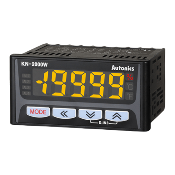
Unit Description
1
1. Display part(red)
● Run mode: Displays current measurement value.
2
3
● Parameter set mode: Displays parameter and SV.
2. Unit indicator: Displays the set unit.
5
3. Alarm output indicator
: Turns ON when the alarm is ON.
4
6
4.
key
: Used to enter parameter set mode, move to parameters, save SV and return to
RUN mode.
5.
,
,
key: Used to change parameter SV.
6. D.IN3
: Press the
and
keys for 3 sec at the same time, it operates the set function
(alarm clear, display hold, zero-point adjustment) at [DI-K] at program mode.
Dimensions
96
10
108
● Panel cut-out
91
Input Type and Range
Input type
Parameter Input range(℃)
TC-K
K(CA)
-200.0 to 1350.0
TC-J
J(IC)
-200.0 to 800.0
E(CR)
TC-E
-200.0 to 800.0
T(CC)
TC-T
-200.0 to 400.0
TC-R
R(PR)
0.0 to 1750.0
B(PR)*
TC-B
400.0 to 1800.0
Thermo
-couple
TC-S
S(PR)*
0.0 to 1750.0
N(NN)*
TC-N
-200.0 to 1300.0
C(W5)*
TC-C
0 to 2300
TC-L
L(IC)*
-200.0 to 900.0
U(CC)*
TC-U
-200.0 to 400.0
TC-P
Platinel II*
0.0 to 1390.0
Cu50Ω*
Cu50
-200.0 to 200.0
※1
Cu100Ω*
Cu10
-200.0 to 200.0
RTD
JPt100Ω
JPt1
-200.0 to 600.0
DPt50Ω
DPt5
-200.0 to 600.0
DPt1
DPt100Ω
-200.0 to 850.0
0.00 - 20.00mA
aMA1
Current
aMA2
4.00 - 20.00mA
19999 to 19999
-50.00 - 50.00mV
aMV1
Analog
(display range is variable
aMV2
-200.0 - 200.0mV
depending on decimal point position)
Voltage
-1.0000 - 1.0000V
A-V1
A-V2
-1.000 - 10.000V
※Above input types which have the * mark are not displayed.
To display the above input types, supply the power with pressing the
Specifications
KN-22
W
Series
KN-2000W
AC voltage
100-240VAC
50 to 60Hz
Power
supply
DC voltage
24VDC
Allowable voltage range 90 to 110% of rated voltage
AC voltage
Max. 8VA
Power
consumption
DC voltage
Max. 3W
Display method
4½-digit, 7-segment LED (selectable red, green, yellow) method
Character size
W10×H17mm
RTD
JPt100Ω, DPt100Ω, DPt50Ω, Cu50Ω, Cu100Ω (5 types)
Thermocouple K, J, E, T, R, B, S, N, C (W5), L, U, PLII (12 types)
Input type
KN-24
W
●Voltage: ±1.0000V, ±50.00mV, ±200.0mV, -1.000-10.000V (4 types)
Analog
●Current: 4.00-20.00mA, 0.00-20.00mA (2 types)
●Contact input: max. 2kΩ in ON,Max. 90kΩ in OFF
●Non-contact input: residual voltage max. 1.0V in ON,
Digital input
●Outflow current: approx. 0.2mA
Alarm output ●2-point: relay contact capacity 250VAC
●4-point: relay contact capacity 250VAC
Sub
Transmission
ISOLATED DC4-20mA (PV transmission) load resistance max. 600Ω
output
output
Com. output
RS485 (Modbus RTU)
±0.2% F.S. ±1-digit (25±5℃)
±0.3% F.S. ±1-digit (-10 to 20℃, 30 to 50℃)
Display accuracy
In case of thermocouple and below -100°C input, [±0.4% F.S.]±1-digit
※TC-T, TC-U is min. ±2.0℃
Setting method
Set by front keys or RS485 communication
Alarm output hysteresis
Set ON/OFF interval (1 to 999-digit)
Sampling cycle
Analog input: 100ms, temperature sensor input: 250ms
Dielectric voltage
2000VAC 50/60Hz for 1 min (between input terminal and power terminal)
0.75 mm amplitude at frequency of 5 to 55Hz (for 1 min) in each X, Y, Z
Vibration
direction for 2 hours
Mechanical: min. 10,000,000,
Relay
2-point
Electrical: min. 100,000 (250VAC 3A resistance load)
life
Mechanical: min. 20,000,000,
cycle
4-point
Electrical: min. 500,000 (250VAC 1A resistance load)
Insulation resistance
Over 100MΩ (at 500VDC megger)
Noise immunity
±2kV the square wave noise (pulse width 1㎲) by noise simulator
Memory retention
Approx. 10 years (non-volatile semiconductor memory type)
Ambient temp. -10 to 50℃, storage: -20 to 60℃
Environ
-ment
Ambient humi. 35 to 85%RH, storage: 35 to 85%RH
(unit: mm)
Approval
Weight
※1
Approx. 332g (approx. 200g)
※ 1: The weight includes packaging. The weight in parenthesis is for unit only.
※ Environment resistance is rated at no freezing or condensation.
Communication
■ Communication set [Program mode: ADDR, BAUD]
You can set communication address [ ADD R] and communication speed [ BA UD] for
RS485 communication.
■ Communication write enable/disable [Program mode: COmW]
90
You can set to enable [ EnA] or disable [ DIsA] or writing parameter setting by RS485
communication.
■ Communication manual
Min. 116
Refer to communication manual for RS485 communication.
Visit our web site (www.konics.com) to download communication manual and software
[Integrated device management program: DAQMaster].
■ Software [Integrated device management
92
+0.6
0
program: DAQMaster]
Integrated device management program,
DAQMaster, is able to set and monitor parameters. It
is available only for RS485 communication models.
Item
Minimum requirements
IBM PC compatible computer with Intel
System
Pentium Ⅲ or above
Input range(℉)
Operating
Microsoft Windows 98/NT/XP/Vista/7/8/10
-328 to 2462
system
-328.0 to 1472.0
Memory
256MB or more
-328.0 to 1472.0
Hard disk
More than 1GB of free hard disk space
-328.0 to 752.0
VGA
1024×768 or higher resolution display
32 to 3182
Others
RS-232 serial port (9-pin), USB port
752 to 3272
※1:
32 to 3182
※2: 1 : Moves digits / 4, 3 : Changes SV.
※3: Press the
-328 to 2372
32 to 4172
※After entering setting group, press the
RUN mode
no additional key operation in 30 sec, it returns to RUN mode.
-328.0 to 1652.0
※
Press
key.
MODE
-328.0 to 752.0
32 to 2534
※1
※2
Alarm 1
S
AL1
09(9
-328.0 to 392.0
value
Set each alarm value; [ AL-1 to AL-4] in program mode.
※3
MODE
MODE
-328.0 to 392.0
• Setting range
-328.0 to 1112.0
Alarm 2
S
AL2
09(9
value
-328.0 to 1112.0
MODE
※When alarm operation [ AL-1 to AL-4] in program mode
-328.0 to 1530.0
Alarm 3
S
AL3
00)1
value
※For model with 2 alarm output (KN-22
MODE
Alarm 4
S
AL4
00)1
value
MODE
High peak
S
Displays high/low peak value.
hPEK
----
value
※High/Low peak value is available only to check and initialize
MODE
※Initial high/low peak is saved after 2 sec from supplying the
Low peak
S
lPEK
----
key.
value
MODE
RUN mode
Press
for 3 sec
IN-P
Input type
MODE
Temperature
UNIT
unit
MODE
Front display
dUNT
unit
leakage current max. 0.03mA in OFF
MODE
Low limit
3A 1c
L-RG
input value
1A 1a
MODE
High limit
H-RG
input value
MODE
Decimal
dP
point
MODE
Low limit
L-SC
scale value
MODE
High limit
H-SC
scale value
MODE
4mA output
lOUT
scale value
MODE
20mA output
hOUT
scale value
MODE
Input and
transmission
EX.I0
output
MODE
extension
AL1 mode
AL-1
MODE
AL-2
AL2 mode
MODE
AL-3
AL3 mode
MODE
AL-4
AL4 mode
MODE
AL output
A-HY
hysteresis
MODE
■ Communication specifications
Item
Specifications
Input special
InSF
function
Com. method RS485 2-wire half duplex
MODE
Com.
19200, 9600, 4800, 2400,
speed(BPS)
1200
Input
IN-B
correction
Converter
Converter built in RS232
MODE
Max.
32 units
MAvF
Digital filter
connections
MODE
Com.
Max. 1200m (within 700m
Digital input
DI-T
distance
recommended)
terminal
Protocol
Modbus 1.1 RTU
MODE
Parity
None
Digital input
DI-K
Stop Bit
1-bit
key
Data length
8-bit
MODE
S
:Press any key among the 1 , 3 , 4 .
CLOR
Display color
MODE
key after checking/changing SV in each parameter.
The value flashes twice and is saved. It moves to next parameter.
MODE
MODE
key for 3 sec or there is
: This parameter may or may not appear, depending on the
Alarm
C-AL
other parameter set or model type.
display color
MODE
※Displayed only for alarm output models.
Sensor
break
BURN
alarm
output
MODE
: Temperature sensor input → within temperature range
Analog input → L-SC to H-SC
Com.
is no alarm [ AT)_] or sensor break alarm [ SBa_], these
ADDR
address
parameters are not displayed.
MODE
W), AL3, AL4 are
Com.
not displayed.
BAUD
speed
MODE
Com.
COmW
write
MODE
it. (Refer to ' High/Low peak monitoring' for initialization.)
LOCK
Lock
power.
MODE
※1:
S
:Press any key among the 1 , 3 , 4 .
※2: 1 : Moves digits / 4, 3 : Changes SV.
※3: Press the
MODE
key after checking/changing SV in each parameter.
The value flashes twice and is saved. It moves to next parameter.
※After entering setting group, press the
key for 3 sec or there is
MODE
no additional key operation in 30 sec, it returns to RUN mode.
key
MODE
※
: This parameter may or may not appear, depending on the
other parameter set or model type.
※1
※2
S
aMA2
Select input type. (Refer to ' Input Type and Range'.)
MODE
※3
※Displayed only when selecting
3
S
temperature sensor input type.
?C
?F
4
※Displayed only when selecting analog input type.
S
3
3
3
?/O
OFF
?C
?F
4
4
4
Select front display unit.
Set low limit of input range.
S
0$00
• Setting range: within analog input type range
Set high limit of input range.
S
2)00
• Setting range: within analog input type range
S
3
3
3
)0
)00
)000
0
4
4
4
Select decimal point position of display scale value.
Set low limit scale value.
S
00)0
• Setting range: -19999 to 19999
Set high limit scale value.
S
10)0
• Setting range: -19999 to 19999
※Displayed only for transmission output model.
Set output scale value for 4mA.
S
00)0
• Setting range: Temperature sensor input → within temperature range,
Analog input → L-SC to H-SC
Set output scale value for 20mA.
S
10)0
• Setting range: Temperature sensor input → within temperature range,
Analog input → L-SC to H-SC
※Displayed only when selecting analog input type.
3
3
S
SP
10P
0P
4
4
Select extension range of 4-20mA input and transmission output.
※Displayed only for alarm output models.
S
AT!A
<Alarm operation> <Alarm option>
S
AL-1
AT!A
AT!A
MODE
MODE
S
AT!A
AL-2
Set AL1 to
AT@A
AT!B
AL4 alarm
MODE
operation
AL-3
S
and option
AT@A
SBa_
AT!C
MODE
AL-4
AT)_
AT!D
MODE
S
AT@A
Next parameter
※SV changing method of AL-2 to AL-4 is same as AL-1's.
※
For model with 2 alarm output
(KN-22
W), AL3, AL4 are not displayed.
※No alarm [ AT)_], sensor break alarm [ SBa_] do not have alarm option.
※Set alarm value [ AL1 to AL4] in monitoring mode.
S
Set alarm output hysteresis. • Setting range: 001 to 999
001
※When alarm operation [ AL-1 to AL-4] in program mode is no alarm
[ AT)_] or sensor break alarm [ SBa_], this parameter is not displayed.
※Displayed only when selecting analog input type.
S
3
3
3
LIN
ROOT
SQAR
TUF
4
4
4
Select input special function.
S
Set input correction value.
0000
• Setting range: -999 to 999
S
Set the number of moving average digital filters.
04
• Setting range: 01 to 16
3
3
S
HOLD
ZERO
AlRE
4
4
Select digital input function by no. 6 and 7.
※For the model without alarm output (KN-20
W), AlRE is not displayed.
3
3
S
HOLD
ZERO
AlRE
4
4
Select digital input function by front keys.
※Press the 4 , 3 keys for 3 sec at the same time and it executes the selected function.
※For the model without alarm output (KN-20
W), AlREis not displayed.
3
3
3
3
S
RED
GRN
YELO
R--G
G--R
4
4
4
4
' Display color'.
Select display part color for RUN mode and error
.
※Refer to
※Displayed only for alarm output models.
Select display part color for alarm.
S
RRRR
※Refer to ' Display color'.
※Displayed only for transmission output models.
3
S
ON
OFF
Select output status when sensor disconnection.
4
※Displayed only for RS485 communication output model.
Set communication address.
S
01
• Setting range: 01 to 99
3
3
3
3
S
(6K
1(2K
!2K
@4K
$8K
4
4
4
4
Select communication speed (baud rate).
3
S
DIsA
Select enable/disable to communication write.
EnA
(EnA: enable to write, DIsA: disable to write)
4
3
3
S
OFF
LOC1
LOC2
4
4
Select lock function.
Advertisement
Table of Contents

Summary of Contents for KONICS KN-2000W Series
- Page 1 ※When alarm operation [ AL-1 to AL-4] in program mode is no alarm Failure to follow this instruction may result in shortening the life cycle of the product Visit our web site (www.konics.com) to download communication manual and software MODE [ AT)_] or sensor break alarm [ SBa_], this parameter is not displayed.
- Page 2 When selecting analog input, you can set the input range for your purpose. Set low Temperature transmitters TEL: 82-32-820-2300 / FAX: 82-32-813-9981 Parameter SV Transmission output(4-20mA) E-mail: konics@konics.com limit input value [ L-RG] and high limit input value [ H-RG] to limit the input range. Thermometers A/S center ON 20mA+5% output •Set conditions:...
Need help?
Do you have a question about the KN-2000W Series and is the answer not in the manual?
Questions and answers