Table of Contents
Advertisement
Quick Links
#84631
7" x 16" Variable Speed Mini Lathe
Instruction Manual
Please read and understand all instructions before using this tool.
Note: These instructions will show you how to assemble this machine,
work its controls and maintain it for long life.
It is not intended as an educational course on how to make parts using a lathe.
Made in China for
340 Snyder Avenue
Berkeley Heights, NJ 07922
For technical assistance, call 908-464-1094 Monday thru Friday, 1pm to 5pm ET
©Micro-Mark
MM050310
Advertisement
Table of Contents

Summary of Contents for MicroLux True-Inch 84631
- Page 1 #84631 7” x 16” Variable Speed Mini Lathe Instruction Manual Please read and understand all instructions before using this tool. Note: These instructions will show you how to assemble this machine, work its controls and maintain it for long life. It is not intended as an educational course on how to make parts using a lathe.
-
Page 2: Specifications
SPECIFICATIONS Maximum swing over bed 7” diameter Distance between centers 16” Spindle taper Morse No. 3 (MT3) Tailstock taper Morse No. 2 (MT2) Spindle bore .787” (20 mm) Cross slide travel 2.559” (65 mm) Compound slide travel 2.165” (55 mm) Spindle speed (continuously variable) 0 to 2500 rpm approx. -
Page 3: Before Operation
Before Operation Be sure the switch is OFF when not in use and before plugging in to wall outlet. Do not use inappropriate attachments in an attempt to exceed the toolʼs capacity. Approved accessories are available from Micro-Mark (1-800-225-1066), www.micromark.com. Check for damaged parts. -
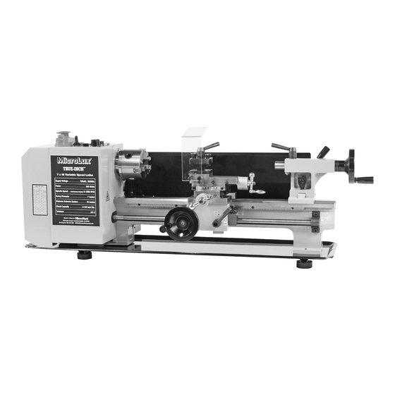
Page 4: Lathe Features
LATHE FEATURES Gear cover Headstock Lead screw 3-jaw chuck Compound slide feed handle Cutter guard Thread dial indicator table Tool post Automatic feed lever Cross-slide Apron Compound slide Dial Tailstock Cross-slide feed Handle Cam action tailstock handle Carriage/saddle Longitudinal Feed Wheel Tailstock spindle feed handle CONTROL PANEL Emergency stop switch... -
Page 5: Running Gear
1. Headstock The motor drives the spindle via an internal tooth belt. Spindle speed is continuously variable, and is regulated by the speed control knob (20) located on the main control panel. The spindle is provided with an internal No. 3 Morse taper (MT3) to accommodate a center, or for use with a face plate or turning clamp. The 3-jaw self-centering chuck (3) is mounted on the spindle flange. -
Page 6: Installation
Unpacking and Preparing for Use (See assembly instructions) Upon receipt, carefully unpack the lathe and inspect it to ensure that no damage was suffered in transit and to account for all parts. Should any damage be apparent, or parts are missing, please contact the carrier and Micro-Mark immediately. The following loose items are to be found in the packing case (fig. -
Page 7: Starting Procedure
STARTING PROCEDURE A. During Installation – Initial Start (fig. 4) Taking all precautions previously stated, turn the speed control knob fully counter-clockwise, setting it to OFF. (You will NOT hear an audible click.) Be sure the cross-slide is well away from the chuck and the automatic feed lever is in its disengaged position (lever is UP). -
Page 8: Operation
OPERATION A. Simple Turning Before starting the machine as described previously, it is imperative that the setup for the type of work to be carried out is fully checked. The following notes are guidelines for setting up the lathe to carry out a simple turning operation. ALWAYS plan your work. -
Page 9: Bevel Cutting
B. Simple Turning With Power Feed The same basic setup is used as described previously, except that, before starting, the lead screw F/N/R Lever (on the rear of headstock) is set to the “Forward” position and the auto feed lever (15) is operated in order to drive the carriage/saddle. As mentioned previously, the rotational speed of the lead screw, and hence the rate of feed of the tool, is dependent upon the gear configuration of the gear train. -
Page 10: Changing Gears For Screw Cutting
CHANGING GEARS FOR SCREW CUTTING The lead screw is driven via a gear train and a gear on the spindle. The gear ratio will determine the rotational speed of the lead screw with relation to the spindle, i.e., one turn of the spindle will turn the lead screw an amount determined by the gear ratio. By setting the gears to a known ratio, we can therefore produce threads of a known size, and as the lead screw supplied produces Imperial threads, the known values will be in Threads Per Inch (TPI). -
Page 11: Maintenance
MAINTENANCE For maximum performance, it is essential that the lathe be properly maintained. Before Use Always inspect before use. Any damage should be repaired and misadjustments rectified. Damage to machined surfaces should be repaired with an oil stone. Test by hand to ensure smooth operation of all parts before use. Apply a few drops of oil to the oil ways at both lead screw bearings (at each end bracket) and add more once or twice during the day if used continuously. - Page 12 ACCESSORIES A complete range of accessories is available from Micro-Mark. Please see a recent catalog or visit the website at www.micromark.com for the latest selection. External Jaws for 3-Jaw Chuck To change the jaws, insert the chuck key and open the jaws to their fullest extent. It will then be possible to remove each jaw in turn.
-
Page 14: Parts List
Parts List Drawing # Description Qty. Drawing # Description Qty. GB 278-89 - 80206 Bearing 80206 GB 70-85 - M4 x 10 Screw M4*10 CN10203 Cover GB 41-86 - M 8 Nut M8 GB 70-85 - M5 x 12 Screw M5*12 GB 65-85 - M8 x 55 Screw M8*55 C2A0208... - Page 15 Parts List (continued) Drawing # Description Qty. Drawing # Description Qty. C2A03A0102B Plate of tailstock GB 96-85 - 5 Washer C2A0306 Washer GB 93-87 - M5 Spring washer C2A0304 Tailstock screw GB 818-85 - M5 x 10 Screw C2A0305 Flange C2A0805 Bolt C2A0303...
Need help?
Do you have a question about the True-Inch 84631 and is the answer not in the manual?
Questions and answers