
Related Manuals for AdvanPOS CP-2010 Series

Summary of Contents for AdvanPOS CP-2010 Series
- Page 1 CP-2010 Series Price Checker POS System User Manual Before installing and operating the unit, please read this user manual thoroughly and retain for reference. Ver 1.0_2011/04/11...
-
Page 2: How To Use This Manual
How to Use This Manual This manual contains information to set up and use the CP-2010. In addition, instructions are included for added hardware, software, upgrades, and optional items. Chapter 1 An introduction to what you find in the CP-2010 and an overview of product specifications, appearance, and interface. - Page 3 Federal Communications Commission (FCC) Notice This equipment has been tested and found to comply with the limits for a Class A digital device, pursuant to Part 15 of the FCC Rules. These limits are designed to provide reasonable protection against harmful interference in a residential installation.
- Page 4 Copyright The information in this guide is subject to change without prior notice. The manufacturer shall not be liable for technical or editorial errors or omissions contained herein, nor for incidental or consequential damages resulting from the furnishing, performance, or use of this material. This manual contains information protected by copyright.
- Page 5 Precautions 1. Please read these safety instructions carefully. 2. Keep this User Manual for later reference. 3. Disconnect this equipment from the AC outlet before cleaning. Do not use liquid or spray detergent for cleaning. Use only a moistened sheet or cloth. 4.
-
Page 6: Table Of Contents
Contents Chapter 1 Introduction ....................1 Features ............................. 1 Specifications ............................1 Package Contents ..........................2 Base System and Options ........................3 Dimensions ............................4 Connector Panel ..........................5 Chapter 2 Standard Hardware and Upgrades ............... 6 Precautions ............................6 Removing Scanner Module ........................ -
Page 7: Chapter 1 Introduction
Chapter 1 Introduction Features 8.9 inch TFT touch screen Fanless operation 75mm VESA compatible installation Ideal for price checking, verification or stock checking IP65 sealed front touch panel 2 x COM, 4 x USB, 1 x SD ... -
Page 8: Package Contents
Scan Pattern 5 directions of scan field Scan Rate 1,200 scans per second Minimum Bar Width 5mil @ PCS=90% Interface A-52M 2D Imagine Scanner Aiming Element 650nm visible laser diode (VLD) Optical System 640 x 480 pixels (VGA type CCD) Field of View 32.2°... -
Page 9: Base System And Options
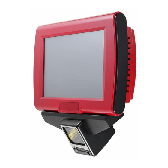
Wall Mount Swing Arm Kit (optional) Base System and Options Before you begin, take a few moments to become familiar with the CP-2010. 8.9 inch TFT LCD choices: •LCD with tempered glass •LCD with 5 wire resistive touch System Box Internal Speaker I/O Panel I/O Panel... -
Page 10: Dimensions
Dimensions (Unit: mm) CP-2010 and A-50M Dimensions CP-2010 and A-52M Dimensions... -
Page 11: Connector Panel
Connector Panel The CP-2010's primary connector panel is located at the rear. 4 x USB COM3 (RI/5V/12V) 12VDC In Power Switch COM1 (RI/5V/12V) -
Page 12: Standard Hardware And Upgrades
Chapter 2 Standard Hardware and Upgrades Precautions Before performing hardware changes, be sure to carefully read all of the applicable instructions, cautions, and warnings in this guide. WARNING! To reduce the risk of personal injury from electrical shock, hot surfaces, or fire: Disconnect the power cord from the wall outlet and allow the internal system components to cool before touching. -
Page 13: Removing Scanner Module
Removing Scanner Module Turn off the system power properly through the operating system, then turn off any external devices. Disconnect the power cord from the power outlet and disconnect any external devices. CAUTION: Regardless of the power-on state, voltage is always present on the main board as long as the system is plugged into an active AC outlet. -
Page 14: Opening Bottom Covers
Opening Bottom Covers CAUTION: To prevent loss of work and damage to the system or drive: If you are inserting or removing a drive, shut down the operating system properly, turn off the system, and unplug the power cord. Do not remove a drive while the system is on or in standby mode. - Page 15 7. Remove the eight screws that secure the metal bottom cover to the main unit. 8. Lift off the metal bottom cover in the direction of the arrow.
-
Page 16: Cpu Module Replacement
CPU Module Replacement WARNING! If the CPU Module has been unloaded, the real Date/Time, and BIOS settings have to reset every time t o ensure the system boot normally. 1. Turn off the system power properly through the operating system, then turn off any external devices. - Page 17 7. Reattach the heatsink and make sure the heatsink bottom’s thermal pad and the top of the CPU are in total contact to prevent the CPU from overheating. Overheating may result in unstable system performance. 8. Reattach the bottom covers and scanner module. 9.
-
Page 18: Sata Hard Disk Replacement
SATA Hard Disk Replacement NOTE: This system does not support Parallel ATA (PATA) hard drives. Before removing the original hard drive, be sure to back up its data so that you can transfer the data to the replacement hard drive. Also, if you are replacing the primary hard drive, make sure you have a recovery disc set to restore the operating system, software drivers, and any software applications that were preinstalled on the system. - Page 19 6. From the sides of the HDD holder, remove all four screws and lift out the hard disk. 7. Insert the replacement hard disk into the HDD holder, and reattach the screws. 8. Replace the HDD holder back onto the main board. 9.
-
Page 20: Chapter 3 Optional Components
Chapter 3 Optional Components Wall Mount Swing Arm Kit Installation Select a flat surface of adequate strength, ensuring there will be proper ventilation and maneuvering space. Please use the right tools and accessories according to the surface material (drywall, concrete, solid wood, etc.) to securely support the system box. - Page 21 3. Secure the holder plate to the main unit with four screws, as shown. 4. Affix the main unit to the swing arm by sliding the holder plate back into its swing arm holder. 5. After the main unit is attached, replace the two thumb screws to secure the panel.
-
Page 22: Chapter 4 Cp-2010 Carry Board Configuration
Chapter 4 CP-2010 Carry Board Configuration Jumper and Connector Locations Connector Allocation Connector Function Battery Connector SD Memory Card Socket DMP_BUS1 SO-DIMM CPU Module Connector SATA HDD Power Connector SATA1 SATA Connector USB2 USB Pin Header Audio Audio LINE_OUT & LINE_IN Connector SPEAK Speaker Connector Touch1... -
Page 23: Connector Pin Assignments
POWER DC JACK COM1 RI Function Setup Connector COM3 RI Function Setup Connector Connector Pin Assignments Power DC Jack PIN No. Description PIN No. Description +12VDC COM1/COM4 COM1/COM3 Port Connector PIN No. Description PIN No. Description LPT1 Print Port Connector PIN No. -
Page 24: Jumper Settings
USB_B1/USB_B2 USB Dual Connector PIN No. Description PIN No. Description DT0- DT0+ DT1- DT1+ SD Memory Card Slot PIN No. Description PIN No. Description SDA_D3 SDA_CMD VCCSDA SDA_CLK SDA_D0 SDA_D1 SDA_D2 SDA_CD SDA_WP Jumper Settings To set jumper positions, place the jumper shunt over the pins designated in the table (SHORT) or remove (NC) it from the jumper pins and store for future use. - Page 25 NOTE: Wrong voltage selection may damage the COM Port device. Please survey COM port device’s RI before setup this jumper setting.
-
Page 26: Chapter 5 Software Setup
Chapter 5 Software Setup This system comes with a variety of drivers for different operating systems. A software CD is included in the package contents. Driver Software List Driver Driver Setup Location MSTI Graphics <CD>:\Drive\MB\PMX-1000\VGA\D1010_R8 RealTek Audio <CD>:\Driver\MB\PMX-1000\Audio\ALC262_Codec_WDM_R223 PCI-E Ethernet <CD>:\Driver\MB\PMX-1000\Ethernet\A9120_MAC_2008_09_10 Abon Touch Screen <CD>:\Driver\Peripheral\Touch\Abon... -
Page 27: Msti Graphics Driver Installation
MSTI Graphics Driver Installation 1. Locate and Run the D1010_R8.msi file on the CD in folder <CD>:\Driver\MB\PMX-1000\VGA\D1010_R8 3. Click Next after making sure the check boxes 2. Click Next on the Welcome screen. shown are marked. 5. Click Continue Anyway on the software 4. -
Page 28: Audio Driver Installation
Audio Driver Installation 1. Locate and Run the Setup.exe file on the CD in folder<CD>:\Driver\MB\PMX-100\Audio\ ALC262_Codec_WDM_R223 3. When installation is complete, select Yes and 2. Click Next on the Welcome screen. click Finish to restart the system. -
Page 29: Ethernet Driver Installation
Ethernet Driver Installation 1. Select My Computer on the desktop and then 2. Select Hardware and then Click Device Manager. right-click to set properties. 3. Select Ethernet Controller and then right click to 4. Select Yes, this time only and then click Next. Update Driver. - Page 30 7. Click Continue Anyway on the Hardware 8. Click OK after making sure the check boxes Installation screen. shown. 10. The system Device Manager will aware the 9. When installation is complete, click Finish. Ethernet device.
-
Page 31: Abon Touch Screen Driver Installation
Abon Touch Screen Driver Installation 1. Locate and Run the autorun.exe file on the CD in folder <CD>:\Driver\Peripheral\Touch\Abon 2. Select Setup Touch Package (for all Windows- 3. Click Next on the Welcome screen. Vista32). 4. Click Next. 5. Select Install RS232 driver and click Next. 6. - Page 32 8. Click Continue Anyway. 9. Click OK to reboot the system. 10. Run the Touch Tool on the desktop. 11. Select Advance, then click 4 Pts Calibration.
- Page 33 Scanner Driver Installation For further detailed scanner’s setting and programming, please refer to the scanner user’s manual and programming guide. Go to <CD>\Optional Module Data & Tool\Scanner\A-50M or A-52M...
Need help?
Do you have a question about the CP-2010 Series and is the answer not in the manual?
Questions and answers