Advertisement
Advertisement

Subscribe to Our Youtube Channel
Summary of Contents for TTI TF930
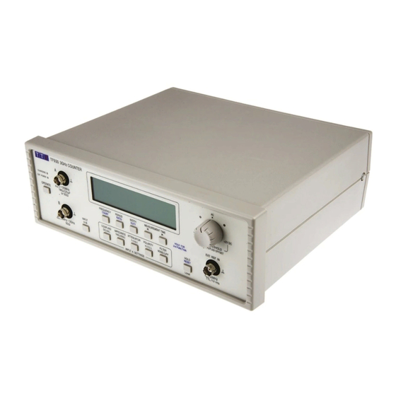
- Page 1 TF930 & TF960 3GHz & 6GHz Universal Counters SERVICE GUIDE...
-
Page 2: Table Of Contents
Table of Contents Specifications Safety General Frequency Calibration C Input Threshold Adjustment Diagnostic Notes Battery replacement Parts List... -
Page 3: Specifications
Specifications Input Specifications Input A Configurable options Input coupling: AC or DC Input impedance: 1MΩ or 50Ω Attenuation: 1:1 or 5:1 Active edge: Rising or falling, or width high or low Low pass filter: Filter In (~50kHz cut-off) or Out Trigger threshold: Variable threshold for both DC and AC coupling Input Impedance:... - Page 4 Timebase Measurement Clock: 50MHz. Internal Reference oscillator: 10MHz TCXO with electronic calibration adjustment. Oscillator Temperature Stability: Better than ± 1ppm over rated temperature range. Initial Oscillator Adjustment Error: < ± 0.2ppm at 21ºC. Oscillator Ageing Rate: < ± 1ppm first year. Calibration adjustment range: >...
- Page 5 Current consumption: < 100mA (<5mA if AC adaptor power is present) Command set: Instrument specific. TF830 and TF930 compatible. Power Requirements The instrument has fixed internal rechargeable batteries and is supplied with a universal voltage external mains adaptor with interchangeable UK, Euro, Australian and US power connectors.
-
Page 6: Safety
Class II (double insulated) device, fully approved to EN 60950-1 (2001), UL 60950 (UL listing E138754) and AS/NZS CISPR:2002 (C-Tick). Use ONLY the AC adaptor/charger provided by TTi with the instrument. Use of any other power source may damage the unit and will void the... -
Page 7: General
General Service Handling Precautions Service work or calibration should only be carried out by skilled engineers using high quality test equipment. If the user is in any doubt as to his competence to carry out the work, the instrument should be returned to the manufacturer or their agent overseas for the work to be carried out. This simplified service guide only details the routine calibration procedure and the dismantling of the instrument to PCB assembly level. -
Page 8: Frequency Calibration
A Standard Frequency Source with accuracy ±0.05ppm or better at a frequency of 5MHz or 10MHz. Ideally use a 10MHz Rubidium source. The procedure below assumes 10MHz. TF930 and TF960 Reference Oscillator Specification. Temperature coefficient: ± 1 ppm over the full operating temperature range. -
Page 9: C Input Threshold Adjustment
reasonable to set the calibration value to within ±0.05ppm. This is typical of the variation over normal room temperature changes during the course of a day. Finally, press and hold down the Width key for a few seconds to store the calibration value in EEPROM. -
Page 10: Diagnostic Notes
Diagnostic Notes This instrument uses many small surface mount components in critical high frequency circuits. Component level fault finding and repair is not possible and service is normally performed by identifying the faulty PCB assembly and returning it to the manufacturer or their field service agent for repair or replacement. - Page 11 If a charge termination fault is suspected, return the charger PCB for replacement as it is not safe to have the batteries continuously charged. There are four different charge termination circuits and an immediate recharge prevention circuit: do not attempt diagnosis. USB faults Use the AC adaptor to power the unit while attempting to diagnose USB problems.
-
Page 12: Battery Replacement
Battery replacement The battery consists of three 2.5Ah NiMH cells. They are conservatively constructed and should provide hundreds of charge-discharge cycles. Extended storage or use in high temperature environments may reduce cell life. If it appears that the discharge time has reduced significantly, or if the cell voltages have become mismatched, then the cells may be replaced. -
Page 13: Parts List
48511-1110CD CD – UNIVERSAL PRODUCT DATA INCLUDES USB DRIVERS TF930 Items 33331-4690 FRONT PANEL – TF930 33331-9780 OVERLAY – FRONT PANEL – TF930 44813-0400 PCB ASSEMBLY – MAIN – TF930 48581-1400 INSTRUCTION BOOK TF930 TF960 Items 33331-1690 FRONT PANEL – TF960 33331-1700 OVERLAY –... - Page 14 Thurlby Thandar Instruments Ltd. Glebe Road • Huntingdon • Cambridgeshire • PE29 7DR • England (United Kingdom) Telephone: +44 (0)1480 412451 • Fax: +44 (0)1480 450409 International web site: www.aimt t i.com • UK web site: www.aimt t i.co.uk Email: info@aimt t i.com Aim Instruments and Thurlby Thandar Instruments Book Part No.
Need help?
Do you have a question about the TF930 and is the answer not in the manual?
Questions and answers