Advertisement
Quick Links
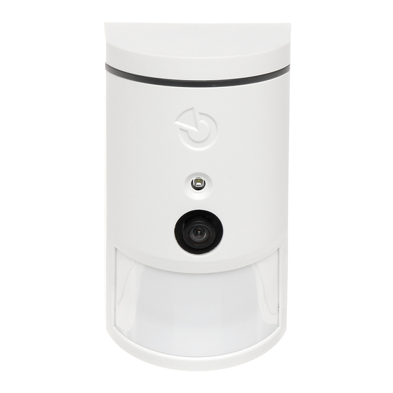
JA-120PC (90) PIR motion BUS detector with a 90° verification camera
This device is a bus component of the JABLOTRON JA-100 system.
It serves for the detection of human movement in building interiors and visual
alarm confirmation. The camera takes colour photos with a resolution of up to
640x480 pixels. The camera trigger follows detected movement, which
ensures that the cause of the alarm is always recorded. The camera
is equipped with a visible flash for taking photos in the dark. The images are
saved in the internal memory of the detector and then they are forwarded
to the control panel and from the control panel they can be sent
to MyJABLOTRON, ARC and a user. The detector can also take a picture
by request. The detector should be installed by a trained technician with
a valid certificate issued by an authorised distributor.
Installation
The detector can be installed on
the wall or in the corner of a room.
There should be no objects that can
quickly
change
temperature
(e.g.
heating appliances) or which move
(e.g.
curtains
hanging
above
a radiator, robotic vacuum cleaners)
or pets in the detector's field of sight.
It is not recommended to install the
detector
opposite
windows
or in places with intense air circulation
(close to ventilators, heat sources, air
conditioning outlets, unsealed doors,
etc.). There should be no obstacles in
front of the detector which might
obstruct its view of the protected area.
Figure: 1 – flash for illumination; 2 – camera lens;
3 – PIR detector lens; 4 – cover tab;
Avoid installation too close to a ceiling. Using
the flash may cause over-exposure of the scene
due to reflections.
1.
Open the detector cover (by pushing the cover tab (4)). Avoid touching
the PIR sensor inside (14) – you could damage it.
2.
Take out the PCB – it is held by a tab (9).
3.
The recommended detector installation height is 2.5m above the floor.
4.
Attach the plastic base to the wall using screws (vertically, with the cover
tab facing downwards).
5.
Re-insert the PCB and connect the BUS cables to the terminals (11)
6.
Plug the connecting cable (6) into the connector on the PCB.
Always switch the system power off before
connecting the detector to the system BUS.
Figure: 5 – Camera module; 6 – connecting cable; 7 – production code;
8 – red LED indicator; 9 – PCB tab; 10 – yellow LED indicator;
11 – BUS terminals; 12 – BUS cable; 13 – tamper contact; 14 – PIR sensor;
15 – Micro SD memory card; 16 – yellow LED Micro SD card indicator
7.
Proceed according to the control panel installation manual. Basic
procedure:
a.
When the device is switched on, the yellow LED indicator (10) starts
flashing repeatedly to indicate that the module has not been
enrolled into the system.
b.
Go
to
the
F-Link
software,
in the Devices tab and launch the enrollment mode by clicking
on the Enroll button.
c.
Press
the
Scan/add
the JA-120PC 90° detector and confirm by double clicking on it.
The detector will be enrolled and the yellow LED indicator (10) will
go off.
JA-120PC (90) BUS PIR motion BUS detector with a 90° verification camera
select
the
required
position
new
BUS
devices
button,
d.
If the detector is enrolled as a first camera PIR or a control panel
is not connected to an external mass storage, F-Link shows
a dialogue window with the question: "Enable image transfer
to external storage?" We recommend enabling this option with
the agreement of the customer and confirming this acceptance
by recording it in the system service log with his signature.
Note: If the transmission is not enabled, images will be saved in the
internal memory of the detector and the control panel. Then it won't
be possible to send images to users' cell phones and e-mails.
8.
Close the detector cover and test its functionality.
:
Notes
-
The detector can be also enrolled by pressing the front tamper contact
(13).
-
Or the detector can be enrolled by entering the serial number (7)
in the F-Link software (or using a bar code reader). Enter all digits
located below the bar code (1400-00-0000-0001).
-
If you want to remove the detector from the system, erase it from
its position in the control panel.
-
In order to comply with the EN 50131-2-4 norm, the cover tab (4) must
be secured with the supplied screw.
Detector internal settings
Settings can be made using F-Link software. In the Devices tab use
the Internal settings option on the detector's position to open a dialog
window where you can configure the settings (* default settings):
LED movement indication: Disables/*Enables movement indication with
the red LED (8) during operation. Always indicates service mode.
PIR immunity level: Defines false alarm immunity. The *Standard level
combines basic immunity with a rapid reaction. The Increased level provides
higher immunity but the detector reaction is slower.
LQ photo quality: Standard* quality uses optimized compression in order
to achieve the fastest possible transfer to the ARC or to the end user
in MyJABLOTRON. The goal is achieving alarm verification in the fastest time
possible. If the quality is switched to Extended, the system will use lower image
compression which will at least double the time necessary to transfer the image
(depends on the conditions of the captured scene). Change the quality only if
the LQ image does not have the quality required by the customer – it may depend
on the captured space. It is not recommended when there are more verification
detectors in the premises which may take images at the same time.
Taking photos during alarms: No flash, *With flash
Flash intensity: Low, *Medium, High – if the captured scene is over-exposed
(e.g.in a small room), the intensity of the flash can be decreased. It can be
increased for larger spaces.
PG output reaction: You can select PG outputs, whose activation will trigger
taking a picture (* No, camera does not react to PG). For further info see
Installation recommendations, cautions.
Taking a photo by PG activation: No flash, *With flash
Taking photos during entrance delay: *No flash, With flash
Send pre-alarm photos: This option is not available when the Extended LQ
photo quality is selected due to more than double size of the photo and therefore
longer transmission time. When this parameter is enabled the detector will send
photos even when the detector is configured with repeated or confirmed reaction
and the alarm has not been confirmed. During every entrance delay, up to two
photos can be taken when the detector is triggered even when the system has
been unset properly.
This option will noticeably increase the volume of data transferred
to MyJABLOTRON or external mass storage. If the system is unset (alarm
is triggered), the images taken during the entrance delay will be sent automatically
regardless of this option.
Test: takes a test photo (LQ) with a flash and F-Link displays it. When the
Detail button is pressed, the F-Link software shows the picture in a 640x480 px
resolution. Photos are sent to the external mass storage (provided that transferring
is enabled).
To set the JA-120PC (90) detector to comply
with security grade 2 or other requirements use
F-Link SW, Parameters tab and the option
"System profiles".
Camera and basic reactions
The process of how the camera takes pictures depends on the settings
in the F-Link software – under the Devices tab. Choose a type of Reaction
on the detector's position.
Instant: During an alarm triggered by the detector, the camera can be activated
up to 3 times (then it will be auto-bypassed). Each activation, depending
on the detected movement, takes 2 photos maximum. Photos are sent to
the control panel (6 photos maximum).
Delayed: The first activation (entrance delay) takes up to 2 photos depending
on the detected movement and saves them into the internal memory (Send pre-
alarm image disabled). When alarm is triggered, photos are sent from the internal
memory to the control panel. Then the behaviour is the same as with an instant
reaction (8 photos maximum).
select
Warning: When the Device autobypass/3rd alarm is enabled (located
in Settings/Parameters) taking photos is blocked after the 3rd alarm. During
each alarm the detector can be triggered up to three times. This way,
1 / 2
MMP53102
Advertisement

Related Manuals for jablotron JA-120PC


Summary of Contents for jablotron JA-120PC
- Page 1 The detector will be enrolled and the yellow LED indicator (10) will each alarm the detector can be triggered up to three times. This way, go off. JA-120PC (90) BUS PIR motion BUS detector with a 90° verification camera 1 / 2 MMP53102...
- Page 2 (for SMS) or e-mail addresses which will receive or directly to the manufacturer after use. a message when a new picture is taken. MyJABLOTRON can request a new JA-120PC (90) BUS PIR motion BUS detector with a 90° verification camera 2 / 2 MMP53102...