
Related Manuals for Innova 3100


Summary of Contents for Innova 3100
- Page 1 OWNER’S MANUAL The Easiest And Best Way To Troubleshoot 1996 and Newer OBD II Vehicles!
-
Page 2: Table Of Contents
Table of Contents Title Page No. INTRODUCTION Congratulations! ........What is OBD? . -
Page 3: Congratulations
Introduction CONGRATULATIONS! CONGRATULATIONS! on your choice of OBD 2 Code Reader. This powerful tool will help you take charge of your vehicle’s maintenance and servicing needs. Today’s vehicles use Computer Control Systems to ensure peak per-formance and fuel efficiency while reducing pollutants in the vehicle’s emissions. - Page 4 Introduction WHAT IS OBD? WHAT IS OBD? OBD 2 Code Reader is designed to work on all OBD 2 compliant vehicles. All 1996 and newer vehicles (cars, light trucks and SUVs) sold in the United States are OBD 2 compliant. One of the most exciting improvements in the automobile industry was the addition of on- board diagnostics (OBD) on vehicles, or in...
- Page 5 You Can Do It! EASY TO USE - EASY TO VIEW - EASY TO DEFINE Easy To Use ..Connect Code Reader to the vehicle’s test connector. Turn the ignition key "On.” DO NOT start the engine. Code Reader turns “On”...
-
Page 6: Safety First
Safety Precautions SAFETY FIRST! SAFETY FIRST! To avoid personal injury, instrument damage and/or damage to your vehicle; do not use Code Reader before reading this manual. This manual describes common test procedures used by experienced service technicians. Many test procedures require precautions to avoid accidents that can result in personal injury, and/or damage to your vehicle or test equipment. - Page 7 Safety Precautions SAFETY FIRST! To prevent damage to the on-board computer when taking vehicle electrical measurements, always use a digital multimeter with at least 10 megOhms of impedance. The vehicle's battery produces highly flammable hydrogen gas. To prevent an explosion, keep all sparks, heated items and open flames away from the battery.
-
Page 8: Vehicles Covered
About Code Reader VEHICLES COVERED VEHICLES COVERED OBD 2 Code Reader is designed to work on all OBD 2 compliant vehicles. All 1996 and newer vehicles (cars and light trucks) sold in the United States are OBD 2 compliant. Federal law requires that all 1996 and newer cars and light trucks sold in the United States must be OBD 2 compliant;... -
Page 9: Battery Replacement
About Code Reader BATTERY REPLACEMENT Data Link Connector (DLC) Location The 16-pin DLC is usually located under the instrument panel (dash), within 12 inches (300 mm) of center of the panel, on the driver’s side of most vehicles. It should be easily accessible and visible BEHIND NEAR... -
Page 10: Controls And Indicators
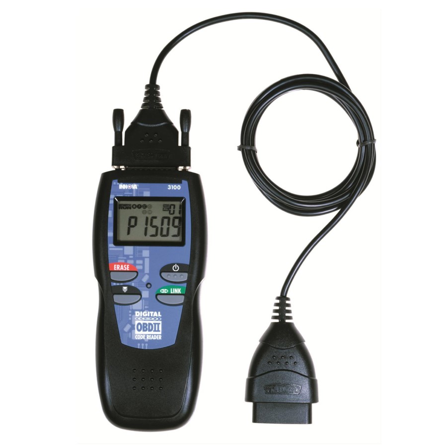
About Code Reader CONTROLS AND INDICATORS CONTROLS AND INDICATORS Figure 1. Controls and Indicators See Figure 1 for the locations of items 1 through 9, below. ERASE button - Erases Diagnostic Trouble Codes (DTCs) and "Freeze Frame" data from your vehicle's computer, and resets Monitor status. -
Page 11: Display Functions
About Code Reader DISPLAY FUNCTIONS 8. LCD Display - Displays test results, Code Reader functions and Monitor status information. See DISPLAY FUNCTIONS, below, for details. 9. Cable - Connects Code Reader to the vehicle's Data Link Connector (DLC). 10. USB Connector - Used to connect USB cable when transferring data batween Code Reader and personal computer. - Page 12 About Code Reader DISPLAY FUNCTIONS 6. FREEZE FRAME icon - Indicates that there is Freeze Frame data from “Priority Code” (Code #1) stored in the vehicle’s computer memory. 7. MIL icon - Indicates the status of the Malfunction Indicator Lamp (MIL).
- Page 13 About Code Reader DISPLAY FUNCTIONS To learn more about Monitors, what they do, and how they work, see OBD 2 MONITORS on page 38. A maximum of eleven Monitors are used on OBD 2 systems. Not all vehicles support all eleven Monitors. When Code Reader is linked to a vehicle, only the icons for Monitors that are supported by the vehicle under test are visible on the display.
-
Page 14: Before You Begin
Preparation for Testing BEFORE YOU BEGIN BEFORE YOU BEGIN OBD 2 Code Reader aids in monitoring electronic- and emissions-related faults in your vehicle and retrieving fault codes related malfunctions in these systems. Mechanical problems such as low oil level or damaged hoses, wiring or electrical connectors can cause poor engine performance and may also cause a "false"... -
Page 15: Vehicle Service Manuals
Preparation for Testing VEHICLE SERVICE MANUALS VEHICLE SERVICE MANUALS Always refer to the manufacturer's service manual for your vehicle before performing any test or repair procedures. Contact your local car dealership, auto parts store or bookstore for availability of these manuals. -
Page 16: Preliminary Vehicle Diagnosis Worksheet
Preparation for Testing PRELIMINARY VEHICLE DIAGNOSIS WORKSHEET PRELIMINARY VEHICLE DIAGNOSIS WORKSHEET The purpose of this form is to help you gather preliminary information on your vehicle before you retrieve codes. By having a complete account of your vehicle's current problem(s), you will be able to systematically pinpoint the problem(s) by comparing your answers to the fault codes you retrieve. - Page 17 Preparation for Testing PRELIMINARY VEHICLE DIAGNOSIS WORKSHEET WHEN DID YOU FIRST NOTICE THE PROBLEM: Just Started Started Last Week Started Last Month Other: LIST ANY REPAIRS DONE IN THE PAST SIX MONTHS: PROBLEMS STARTING No symptoms Cranks, but will not start Will not crank Starts, but takes a long time ENGINE QUITS OR STALLS...
- Page 18 Preparation for Testing PRELIMINARY VEHICLE DIAGNOSIS WORKSHEET AUTOMATIC TRANSMISSION PROBLEMS (if applicable) No symptoms Vehicle does not move when in Shifts too early or too late gear Changes gear incorrectly Jerks or bucks PROBLEM OCCURS Morning Afternoon Anytime ENGINE TEMPERATURE WHEN PROBLEM OCCURS Cold Warm DRIVING CONDITIONS WHEN PROBLEM OCCURS...
-
Page 19: Code Retrieval Procedure
Using Code Reader CODE RETRIEVAL PROCEDURE CODE RETRIEVAL PROCEDURE Retrieving and using Diagnostic Trouble Codes (DTCs) for troubleshooting vehicle operation is only one part of an overall diagnostic strategy. Never replace a part based only on the DTC definition. Each DTC has a set of testing procedures, instructions and flow charts that must be followed to confirm the location of the problem. - Page 20 Using Code Reader CODE RETRIEVAL PROCEDURE If the Code Reader does not turn on automatically when connected to the vehicle, it indicates that there is no power at the vehicle's DLC. Check your fuse panel and replace any burned-out fuses. If replacing the fuse(s) does not correct the problem, consult your vehicle's repair manual to locate the proper computer (PCM) fuse/circuit.
- Page 21 Using Code Reader CODE RETRIEVAL PROCEDURE Green LED - Indicates that all engine systems are "OK" and running normally. All monitors on the vehicle are active and are performing their diagnostic testing, and no trouble codes are present. A zero will show on Code Reader’s LCD display for further confirmation.
-
Page 22: Erasing Diagnostic Trouble Codes (Dtcs)
Using Code Reader ERASING DIAGNOSTIC TROUBLE CODES (DTCs) 7. If more than one code is present, press and release the SCROLL button, as necessary, to display additional codes. Whenever the SCROLL function is used to view additional codes, Code Reader's communication link with the vehicle's computer disconnects. -
Page 23: I/M Readiness Testing
Using Code Reader I/M READINESS TESTING 1. Perform the Code Retrieval Procedure as described on page 17. 2. Wait until the codes are displayed on the Code Reader's LCD and then proceed to step 3. 3. Press and release Code Reader 's ERASE button. - Page 24 Using Code Reader I/M READINESS TESTING On OBD 2 systems, the I/M program is enhanced by requiring vehicles to meet stricter test standards. One of the tests instituted by the Federal Government is called I/M 240. On I/M 240, the vehicle under test is driven under different speeds and load conditions on a dynamometer for 240 seconds, while the vehicle's emissions are measured.
- Page 25 Using Code Reader I/M READINESS TESTING To learn more about Emissions Inspection and Maintenance (I/M) Readiness Monitors, see OBD 2 MONITORS on page 38. Each Monitor has a specific function to test and diagnose only its designated emissions- related component or system. The names of the Monitors (Oxygen Sensor Monitor, Catalyst Monitor, EGR Monitor, Misfire Monitor, etc.) describe which component or system each Monitor...
- Page 26 Using Code Reader I/M READINESS TESTING status. This information is very important since different areas of the state/country have different emissions laws and regulations concerning Monitor Run/Not Run status. Before an Emissions Test (Smog Check) can be performed, your vehicle must meet certain rules, requirements and procedures legislated by the Federal and state (country) governments where you live.
- Page 27 Using Code Reader I/M READINESS TESTING 2. YELLOW LED - Determine from the Code Retrieval Procedure (page 17) which of the two possible conditions is causing the yellow LED to light. If a "PENDING" Diagnostic Trouble Code is causing the yellow LED to light, it is possible that the vehicle will be allowed to be tested for emissions and certified.
- Page 28 Using Code Reader I/M READINESS TESTING Repair the vehicle yourself. If you are going to perform the repairs yourself, proceed by reading the vehicle service manual and following all its procedures and recommendations. Take the vehicle to a professional to have it serviced. The problem(s) causing the red LED to light must be repaired before the vehicle is ready for an Emissions Test (Smog Check).
- Page 29 Using Code Reader WHAT’S NEXT? 4. When a Monitor's Trip Drive Cycle is performed properly, the Monitor icon on Code Reader's LCD display changes from "flashing" to "solid,” indicating that the Monitor has run and finished its diagnostic testing. If, after the Monitor has run, the MIL on the vehicle's dash is not lit, and no codes associated with that particular Monitor are present in the vehicle's computer, the repair was successful.
- Page 30 Using Code Reader WHAT’S NEXT? red LED to light must be repaired before an Emissions Test (Smog Check) can be performed. It is also suggested that the vehicle be inspected/repaired before driving the vehicle further. When inspecting a used vehicle before buying or selling: A GREEN LED indicates that all emissions-related systems are "OK"...
-
Page 31: Computer Engine Controls
Learning More COMPUTER ENGINE CONTROLS COMPUTER ENGINE CONTROLS The Introduction of Electronic Engine Controls Electronic Computer Control Systems make it possible for vehicle manufacturers to comply with the tougher emissions and fuel efficiency standards mandated by State and Federal Governments. As a result of increased air pollution (smog) in large cities, such as Los Angeles, the California Air Resources Board (CARB) and the Environmental Protection Agency... - Page 32 Learning More COMPUTER ENGINE CONTROLS The Basic Engine Computer Control System The Computer Control System consists of an on-board computer and several related control devices (sensors, switches, and actuators). The on-board computer is the heart of the Computer Control System. The computer contains several programs with preset reference values for air/fuel ratio, spark or ignition timing, injector pulse width, engine speed, etc.
- Page 33 Learning More COMPUTER ENGINE CONTROLS The computer compares the values received from these sensors with its preset reference values, and makes corrective actions as needed so that the sensor values always match the preset reference values for the current driving condition. The computer makes adjustments by commanding other devices such as the fuel injectors, idle air control, EGR valve or Ignition Module to perform these actions.
- Page 34 Learning More COMPUTER ENGINE CONTROLS On-Board Diagnostics - Second Generation (OBD 2) In addition to performing all the functions of the OBD 1 System, the The OBD 2 System is an OBD 2 System has been enhanced enhancement of the with new Diagnostic Programs.
- Page 35 Learning More COMPUTER ENGINE CONTROLS The Main Objectives of the OBD 2 System are: To detect degraded and/or failed emissions-related components or systems that could cause tailpipe emissions to exceed by 1.5 times the Federal Test Procedure (FTP) standard. To expand emissions-related system monitoring. This includes a set of computer run diagnostics called Monitors.
- Page 36 Learning More COMPUTER ENGINE CONTROLS Enabling Criteria - Each Monitor is designed to test and monitor the operation of a specific part of the vehicle's emissions system (EGR system, oxygen sensor, catalytic converter, etc.). A specific set of "conditions" or "driving procedures" must be met before the computer can command a Monitor to run tests on its related system.
-
Page 37: Diagnostic Trouble Codes (Dtcs)
Learning More DIAGNOSTIC TROUBLE CODES (DTCs) Do not confuse a "Trip" Drive Cycle with an OBD 2 Drive Cycle. A Trip Drive Cycle provides the "Enabling Criteria" for one specific Monitor to run and complete its diagnostic testing. An OBD 2 Drive Cycle must meet the "Enabling Criteria"... - Page 38 Learning More DIAGNOSTIC TROUBLE CODES (DTCs) OBD 2 DTC EXAMPLE P0201 - Injector Circuit Malfunction, Cylinder 1 P 0 2 0 1 Body Chassis Powertrain Network Generic Manufacturer Specific Identifies the system where the problem is located: Fuel and Air Metering Fuel and Air Metering (injector circuit malfunction only) Ignition System or Misfire...
- Page 39 Learning More DIAGNOSTIC TROUBLE CODES (DTCs) The "Malfunction Indicator Lamp" (MIL) is the accepted term used to describe the lamp on the dashboard that lights to warn the driver that an emissions-related fault has been found. Some manufacturers may still call this lamp a "Check Engine"...
-
Page 40: Obd 2 Monitors
Learning More OBD 2 MONITORS Misfire and fuel system faults require three trips with "similar conditions" before the MIL is turned "Off.” These are trips where the engine load, RPM and temperature are similar to the conditions present when the fault was first found. After the MIL has been turned off, DTCs, Freeze Frame data, and manufacturer-specific enhanced data stay in the computer's memory. - Page 41 Learning More OBD 2 MONITORS 1. Oxygen Sensor Monitor 2. Oxygen Sensor Heater Monitor 3. Catalyst Monitor 4. Heated Catalyst Monitor 5. EGR System Monitor 6. EVAP System Monitor 7. Secondary Air System Monitor 8. Air Conditioning (A/C) Monitor The following provides a brief explanation of the function of each Monitor: Comprehensive Component Monitor (CCM) - This Monitor continuously checks all inputs and outputs from sensors,...
- Page 42 Learning More OBD 2 MONITORS Misfire Monitor - This Monitor continuously checks for engine misfires. A misfire occurs when the air-fuel mixture in the cylinder does not ignite. The misfire Monitor uses changes in crankshaft speed to sense an engine misfire. When a cylinder misfires, it no longer contributes to the speed of the engine, and engine speed decreases each time the affected cylinder(s) misfire.
- Page 43 Learning More OBD 2 MONITORS Heated Catalyst Monitor - Operation of the "heated" catalytic converter is similar to the catalytic converter. The main difference is that a heater is added to bring the catalytic converter to its operating temperature more quickly. This helps reduce emissions by reducing the converter's down time when the engine is cold.
- Page 44 Learning More OBD 2 MONITORS Air Conditioning (A/C) Monitor - The A/C Monitor senses leaks in air conditioning systems that utilize R-12 refrigerant. Vehicle manufacturers have been given two options: 1. Use R-12 refrigerant in their A/C systems, and integrate an A/C Monitor in the OBD 2 systems of these vehicles to detect for refrigerant leaks;...
- Page 45 Learning More OBD 2 MONITORS The oxygen sensor must reach a temperature of at least 600- 650°F, and the engine must reach normal operating temperature, for the computer to enter into closed-loop operation. The oxygen sensor only functions when the computer is in closed-loop. A properly operating oxygen sensor reacts quickly to any change in oxygen content in the exhaust stream.
- Page 46 Learning More OBD 2 MONITORS OBD 2 Reference Table The table below lists current OBD 2 Monitors, and indicates the following for each Monitor: A Monitor Type (how often does the Monitor run; Continuous or Once per trip) B Number of trips needed, with a fault present, to set a pending DTC C Number of consecutive trips needed, with a fault present, to command the MIL “On”...
-
Page 47: Dtc Definitions Diagnostic Trouble Code Definitions
DTC Definitions DIAGNOSTIC TROUBLE CODE DEFINITIONS DIAGNOSTIC TROUBLE CODE DEFINITIONS This section provides the most complete lists of DTC definitions available at the time of publication. OBD 2 is an evolving system; new codes and definitions are added as the system grows. ALWAYS check your vehicle's service manual for code definitions that are not listed here.This section contains both "Generic"... -
Page 48: Generic Dtc Definitions
DTC Definitions GENERIC (P0010 - P0057) GENERIC DTC DEFINITIONS Code Definition P0010 "A" Camshaft Position - Actuator Circuit (Bank 1) P0011 "A" Camshaft Position - Timing Over-Advanced or System Performance (Bank 1) P0012 "A" Camshaft Position - Timing Over-Retarded (Bank 1) P0013 "B"... - Page 49 DTC Definitions GENERIC (P0058 - P0106) Code Definition P0058 HO2S Heater Control Circuit High (Bank 2 Sensor 2) P0062 HO2S Heater Control Circuit (Bank 2 Sensor 3) P0063 HO2S Heater Control Circuit Low (Bank 2 Sensor 3) P0064 HO2S Heater Control Circuit High (Bank 2 Sensor 3) P0065 Air Assisted Injector Control Range/Performance P0066...
- Page 50 DTC Definitions GENERIC (P0107 - P0136) Code Definition P0107 Manifold Absolute Pressure/Barometric Pressure Circuit Low Input P0108 Manifold Absolute Pressure/Barometric Pressure Circuit High Input P0109 Manifold Absolute Pressure/Barometric Pressure Circuit Intermittent P0110 Intake Air Temperature Circuit Malfunction P0111 Intake Air Temperature Circuit Range/Performance Problem P0112 Intake Air Temperature Circuit Low Input P0113...
- Page 51 DTC Definitions GENERIC (P0137 - P0170) Code Definition P0137 O2 Sensor Circuit Low Voltage (Bank 1 Sensor 2) P0138 O2 Sensor Circuit High Voltage (Bank 1 Sensor 2) P0139 O2 Sensor Circuit Slow Response (Bank 1 Sensor 2) P0140 O2 Sensor Circuit No Activity Detected (Bank 1 Sensor 2) P0141 O2 Sensor Heater Circuit Malfunction (Bank 1 Sensor 2) P0142...
- Page 52 DTC Definitions GENERIC (P0171 - P0204) Code Definition P0171 System too Lean (Bank 1) P0172 System too Rich (Bank 1) P0173 Fuel Trim Malfunction (Bank 2) P0174 System too Lean (Bank 2) P0175 System too Rich (Bank 2) P0176 Fuel Composition Sensor Circuit Malfunction P0177 Fuel Composition Sensor Circuit Range/Performance P0178...
- Page 53 DTC Definitions GENERIC (P0205 - P0236) Code Definition P0205 Injector Circuit Malfunction - Cylinder 5 P0206 Injector Circuit Malfunction - Cylinder 6 P0207 Injector Circuit Malfunction - Cylinder 7 P0208 Injector Circuit Malfunction - Cylinder 8 P0209 Injector Circuit Malfunction - Cylinder 9 P0210 Injector Circuit Malfunction - Cylinder 10 P0211...
- Page 54 DTC Definitions GENERIC (P0237 - P0270) Code Definition P0237 Turbocharger Boost Sensor A Circuit Low P0238 Turbocharger Boost Sensor A Circuit High P0239 Turbocharger Boost Sensor B Circuit Malfunction P0240 Turbocharger Boost Sensor B Circuit Range/Performance P0241 Turbocharger Boost Sensor B Circuit Low P0242 Turbocharger Boost Sensor B Circuit High P0243...
- Page 55 DTC Definitions GENERIC (P0271 - P0306) Code Definition P0271 Cylinder 4 Injector Circuit High P0272 Cylinder 4 Contribution/Balance Fault P0273 Cylinder 5 Injector Circuit Low P0274 Cylinder 5 Injector Circuit High P0275 Cylinder 5 Contribution/Balance Fault P0276 Cylinder 6 Injector Circuit Low P0277 Cylinder 6 Injector Circuit High P0278...
- Page 56 DTC Definitions GENERIC (P0307 - P0344) Code Definition P0307 Cylinder 7 Misfire Detected P0308 Cylinder 8 Misfire Detected P0309 Cylinder 9 Misfire Detected P0310 Cylinder 10 Misfire Detected P0311 Cylinder 11 Misfire Detected P0312 Cylinder 12 Misfire Detected P0313 Misfire Detected with Low Fuel P0314 Single Cylinder Misfire (Cylinder not specified) P0320...
- Page 57 DTC Definitions GENERIC (P0345 - P0377) Code Definition P0345 Camshaft Position Sensor "A" Circuit (Bank 2) P0346 Camshaft Position Sensor "A" Circuit Range/Performance (Bank 2) P0347 Camshaft Position Sensor "A" Circuit Low Input (Bank 2) P0348 Camshaft Position Sensor "A" Circuit High Input (Bank 2) P0349 Camshaft Position Sensor "A"...
- Page 58 DTC Definitions GENERIC (P0378 - P0415) Code Definition P0378 Timing Reference High Resolution Signal B Intermittent/Erratic Pulses P0379 Timing Reference High Resolution Signal B No Pulses P0380 Glow Plug/Heater Circuit Malfunction P0381 Glow Plug/Heater Indicator Circuit Malfunction P0382 Glow Plug/Heater Circuit "B" Malfunction P0385 Crankshaft Position Sensor B Circuit Malfunction P0386...
- Page 59 DTC Definitions GENERIC (P0416 - P0445) Code Definition P0416 Secondary Air Injection System Switching Valve B Circuit Open P0417 Secondary Air Injection System Switching Valve B Circuit Shorted P0418 Secondary Air Injection System Relay "A" Circuit Malfunction P0419 Secondary Air Injection System Relay "B" Circuit Malfunction P0420 Catalyst System Efficiency Below Threshold (Bank 1) P0421...
- Page 60 DTC Definitions GENERIC (P0446 - P0473) Code Definition P0446 Evaporative Emission Control System Vent Control Circuit Malfunction P0447 Evaporative Emission Control System Vent Control Open P0448 Evaporative Emission Control System Vent Control Circuit Shorted P0449 Evaporative Emission Control System Vent Valve/Solenoid Circuit Malfunction P0450 Evaporative Emission Control System Pressure Sensor...
- Page 61 DTC Definitions GENERIC (P0474 - P0517) Code Definition P0474 Exhaust Pressure Sensor Intermittent P0475 Exhaust Pressure Control Valve Malfunction P0476 Exhaust Pressure Control Valve Range/Performance P0477 Exhaust Pressure Control Valve Low P0478 Exhaust Pressure Control Valve High P0479 Exhaust Pressure Control Valve Intermittent P0480 Cooling Fan 1 Control Circuit Malfunction P0481...
- Page 62 DTC Definitions GENERIC (P0520 - P0569) Code Definition P0520 Engine Oil Pressure/Switch Circuit Malfunction P0521 Engine Oil Pressure/Switch Range/Performance P0522 Engine Oil Pressure/Switch Low Voltage P0523 Engine Oil Pressure/Switch High Voltage P0524 Engine Oil Pressure Too Low P0530 A/C Refrigerant Pressure Sensor Circuit Malfunction P0531 A/C Refrigerant Pressure Sensor Circuit Range/Performance P0532...
- Page 63 DTC Definitions GENERIC (P0570 - P0635) Code Definition P0570 Cruise Control Accel Signal Malfunction P0571 Cruise Control/Brake Switch A Circuit Malfunction P0572 Cruise Control/Brake Switch A Circuit Low P0573 Cruise Control/Brake Switch A Circuit High P0574 Cruise Control System - Vehicle Speed Too High P0575 Cruise Control Input Circuit P0576...
- Page 64 DTC Definitions GENERIC (P0636 - P0711) Code Definition P0636 Power Steering Control Circuit Low P0637 Power Steering Control Circuit High P0638 Throttle Actuator Control Range/Performance (Bank 1) P0639 Throttle Actuator Control Range/Performance (Bank 2) P0640 Intake Air Heater Control Circuit P0645 A/C Clutch Relay Control Circuit P0646...
- Page 65 DTC Definitions GENERIC (P0712 - P0746) Code Definition P0712 Transmission Fluid Temperature Sensor Circuit Low Input P0713 Transmission Fluid Temperature Sensor Circuit High Input P0714 Transmission Fluid Temperature Sensor Circuit Intermittent P0715 Input/Turbine Speed Sensor Circuit Malfunction P0716 Input/Turbine Speed Sensor Circuit Range/Performance P0717 Input/Turbine Speed Sensor Circuit No Signal P0718...
- Page 66 DTC Definitions GENERIC (P0747 - P0780) Code Definition P0747 Pressure Control Solenoid Stuck On P0748 Pressure Control Solenoid Electrical P0749 Pressure Control Solenoid Intermittent P0750 Shift Solenoid A Malfunction P0751 Shift Solenoid A Performance or Stuck Off P0752 Shift Solenoid A Stuck On P0753 Shift Solenoid A Electrical P0754...
- Page 67 DTC Definitions GENERIC (P0781 - P0816) Code Definition P0781 1-2 Shift Malfunction P0782 2-3 Shift Malfunction P0783 3-4 Shift Malfunction P0784 4-5 Shift Malfunction P0785 Shift/Timing Solenoid Malfunction P0786 Shift/Timing Solenoid Range/Performance P0787 Shift/Timing Solenoid Low P0788 Shift/Timing Solenoid High P0789 Shift/Timing Solenoid Intermittent P0790...
- Page 68 DTC Definitions GENERIC (P0817 - P0849) Code Definition P0817 Starter Disable Circuit P0818 Driveline Disconnect Switch Input Circuit P0820 Gear Lever X-Y Position Sensor Circuit P0821 Gear Lever X Position Circuit P0822 Gear Lever Y Position Circuit P0823 Gear Lever X Position Circuit Intermittent P0824 Gear Lever Y Position Circuit Intermittent P0825...
-
Page 69: Manufacturer Specific Codes - Chrysler
DTC Definitions CHRYSLER (P1103 - P1389) MANUFACTURER SPECIFIC CODES - CHRYSLER Code Definition P1103 Turbocharger Waste Gate Actuator Malfunction P1104 Turbocharger Waste Gate Solenoid Malfunction P1105 Fuel Pressure Solenoid Malfunction P1195 Slow Switching O2 Sensor Bank One Sensor One During catalyst monitoring P1196 Slow Switching O2 Sensor Bank two Sensor one During... - Page 70 DTC Definitions CHRYSLER (P1390 - P1596) Code Definition P1390 Timing belt skipped one tooth or more P1391 Intermittent loss of CMP or CKP P1398 Mis-Fire Adaptive Numerator at Limit (PCM is unable to learn the crank sensors signal for use in preparation for misfire diagnostics P1399 Wait to start lamp circuit...
- Page 71 DTC Definitions CHRYSLER (P1597 - P1899) Code Definition P1597 Speed control switch always low P1598 A/C pressure sensor input voltage too high P1599 A/C pressure sensor input voltage too low P1680 Clutch released switch circuit P1681 No I/P Cluster CCD/ J1850 messages received P1682 Charging system voltage too low P1683...
-
Page 72: Manufacturer Specific Codes - Ford
DTC Definitions FORD (P1000 - P1133) MANUFACTURER SPECIFIC CODES - FORD Code Definition P1000 OBD Systems Readiness Test Not Complete P1001 KOER Not Able to Complete, KOER Aborted P1100 Mass Air Flow Sensor Circuit Intermittent P1101 Mass Air Flow Sensor Out Of Self Test Range P1105 Dual Alternator Upper Fault P1106... - Page 73 DTC Definitions FORD (P1134 - P1187) Code Definition P1134 Bank 1 Fuel Control Shifted Rich (FAOSC) P1135 Pedal Position Sensor A Circuit Intermittent P1137 Lack of HO2S12 Switches - Sensor Indicates Lean P1138 Lack of HO2S12 Switches - Sensor Indicates Rich P1139 Water in Fuel Indicator Circuit P1140...
- Page 74 DTC Definitions FORD (P1188 - P1232) Code Definition P1188 Calibration Memory P1189 Pump Speed Signal P1190 Calibration Resistor Out Of Range P1191 Key Line Voltage P1192 V External P1193 EGR Driver Over Current P1194 ECM/PCM A/D Converter P1195 SCP HBCC Chip Failed to Initialize P1196 Key Off Voltage High P1197...
- Page 75 DTC Definitions FORD (P1233 - P1271) Code Definition P1233 Fuel Pump Driver Module Disabled or Off Line (Fuel Pump Driver Module) P1234 Fuel Pump Driver Module Disabled or Off Line (Fuel Pump Driver Module) P1235 Fuel Pump Control Out Of Range (Fuel Pump Driver Module/ VLCM) P1236 Fuel Pump Control Out Of Range (Fuel Pump Driver Module)
- Page 76 DTC Definitions FORD (P1272 - P1306) Code Definition P1272 Cylinder #2 High To Low Side Open P1273 Cylinder #3 High To Low Side Open P1274 Cylinder #4 High To Low Side Open P1275 Cylinder #5 High To Low Side Open P1276 Cylinder #6 High To Low Side Open P1277...
- Page 77 DTC Definitions FORD (P1307 - P1400) Code Definition P1307 Kickdown Relay Hold Circuit P1309 Misfire Monitor AICE Chip Fault, Misfire Monitor Disabled P1310 Ionization Misfire Detection Module Fault P1311 Ionization Misfire Detection Module Communication Fault P1316 IDM Codes Detected P1340 Camshaft Position Sensor B Circuit P1351 Ignition Diagnostic Monitor Input Circuit...
- Page 78 DTC Definitions FORD (P1401 - P1469) Code Definition P1401 Differential Pressure Feedback EGR Circuit High Input P1402 Exhaust Gas Recirculation Metering Orifice Restricted P1403 Differential Pressure Feedback Sensor Hoses Reversed P1404 EGR Temperature Sensor Circuit P1405 Differential Pressure Feedback Sensor Upstream Hose Off Or Plugged P1406 Differential Pressure Feedback Sensor Downstream Hose Off...
- Page 79 DTC Definitions FORD (P1473 - P1566) Code Definition P1473 Fan Circuit Open (VLCM) P1474 Fan Control Primary Circuit P1479 High Fan Control Primary Circuit P1480 Fan Secondary Low With Low Fan On P1481 Fan Secondary Low With High Fan On P1482 P1483 Brake Pedal Input Short To Battery...
- Page 80 DTC Definitions FORD (P1567 - P1625) Code Definition P1567 Speed Control Output Circuit P1568 Speed Control Unable To Hold Speed P1572 Brake Pedal Switch Circuit P1573 Throttle Position Not Available P1574 Throttle Position Sensor Outputs Disagree P1575 Pedal Position Out Of Self Test Range P1576 Pedal Position Not Available P1577...
- Page 81 DTC Definitions FORD (P1626 - P1716) Code Definition P1626 A/C Circuit Open to Power B+ (VLCM) P1633 Keep Alive Power Voltage Too Low P1635 Tire/Axle Out of Acceptable Range P1636 Inductive Signature Chip Communication Error P1639 Vehicle ID Block Corrupted, Not Programmed P1640 Powertrain DTCs Available In Another Control Module (Ref.
- Page 82 DTC Definitions FORD (P1717 - P1785) Code Definition P1717 Shift Solenoid D Inductive Signature P1718 Transmission Fluid Temperature Sensor In Range Failure (>250 deg F) P1727 Coast Clutch Solenoid Inductive Signature P1728 Transmission Slip P1729 4x4L Switch P1731 1-2 Shift Malfunction P1732 2-3 Shift Malfunction P1733...
- Page 83 DTC Definitions FORD (P1786 - P1882) Code Definition P1786 3-2 Downshift Error P1787 2-1 Downshift Error P1788 Pressure Control Solenoid B Open Circuit P1789 Pressure Control Solenoid B Short Circuit P1795 Inconsistent CAN Level P1804 4-Wheel Drive High Indicator Circuit Open or Shorted To Ground P1806 4-Wheel Drive High Indicator Short To Battery P1808...
- Page 84 DTC Definitions FORD (P1883 - P1901) Code Definition P1883 Engine Coolant Level Switch Circuit P1884 Engine Coolant Level Lamp Circuit Short To Ground P1891 Transfer Case Contact Plate Ground Return Open Circuit P1900 Output Shaft Speed Sensor Circuit Intermittent P1901 Turbine Shaft Speed Sensor Circuit Intermittent OBD 2...
-
Page 85: Manufacturer Specific Codes - General Motors
DTC Definitions GENERAL MOTORS (P1031 - P1188) MANUFACTURER SPECIFIC CODES - GENERAL MOTORS Code Definition P1031 H02 Sensor Heater Control Circuit Problem P1106 MAP Sensor Circuit Intermittent High or Low Voltage P1107 MAP Sensor Circuit Intermittent Voltage Low P1108 BARO to MAP Signal Circuit Comparison Too High P1111 IAT Sensor Circuit Intermittent Voltage High P1112... - Page 86 DTC Definitions GENERAL MOTORS (P1188 - P1320) Code Definition P1188 Engine Oil Pressure Sensor Circuit Voltage High (1997 Corvette) P1189 Engine Oil Pressure Switch Circuit P1200 Injector Control Circuit P1214 Injection Pump Timing Offset P1215 Generator Driver Circuit P1216 Fuel Solenoid Response Time Too Short P1217 Fuel Solenoid Response Time Too Long P1218...
- Page 87 DTC Definitions GENERAL MOTORS (P1323 - P1406) Code Definition P1323 ICM 24X Reference Circuit Low Frequency P1335 Crankshaft Positioning Sensing Circuit P1336 CKP System Variation Not Learned P1345 Camshaft To Crankshaft Position Correlation Fault P1346 CKP Sensor System Variation Not Learned/ Intake Camshaft Position Performance P1349 Intake Camshaft Position System...
- Page 88 DTC Definitions GENERAL MOTORS (P1408 - P1527) Code Definition P1408 MAP Sensor Circuit P1410 Fuel Tank Pressure System P1415 AIR System Bank 1 P1416 AIR System Bank 2 P1431 Fuel Level Sensor 2 Circuit Performance P1432 Fuel Level Sensor 2 Circuit Voltage Low P1433 Fuel Level Sensor 2 Circuit Voltage High P1441...
- Page 89 DTC Definitions GENERAL MOTORS (P1530 - P1571) Code Definition P1530 Ignition Timing Adjustment Switch Circuit P1530 A/C Refrigerant Pressure Sensor Error P1531 Low Air Conditioning Refrigerant Charge P1532 A/C Evaporator Temperature Circuit Voltage Low P1533 A/C Low Side Temperature Sensor Circuit P1535 A/C/ High Side Temperature Sensor Circuit P1536...
- Page 90 DTC Definitions GENERAL MOTORS (P1571 - P1610) Code Definition P1571 Traction Control System PWM Circuit No Frequency (4.0L & 4.6L) P1571 ASR Desired Torque (1997-98 5.7L Corvette) P1572 Traction Control System Active Circuit Voltage Low Too Long P1573 PCM/EBTCM Serial Data Circuit P1573 Engine Hot Lamp Control Circuit P1574...
- Page 91 DTC Definitions GENERAL MOTORS (P1610 - P1642) Code Definition P1610 Standard Body Module Series Data CKT (1998) P1611 Loss Of CVRTD Serial Data P1617 Engine Oil Level Switch Circuit P1619 Engine Oil Lite Monitor Reset Circuit P1620 Low Engine Coolant Level (Saturn) P1621 PCM Memory Performance (Except 1998 5.7L) P1621...
- Page 92 DTC Definitions GENERAL MOTORS (P1642 - P1663) Code Definition P1642 AIR Control Circuit (3.4L) P1642 Change Oil Lamp Control Circuit (1998 3.1L Lumina & Monte Carlo) P1643 Fuel Pump PWM Control Circuit (Except 5.7L VINs P & 5) P1643 Engine RPM Output Circuit (5.7L VINs P & 5) P1644 Delivered Torque Output Circuit P1645...
- Page 93 DTC Definitions GENERAL MOTORS (P1664 - P1825) Code Definition P1664 Skip Shift 1-4 Upshift Lamp Control Circuit P1665 DBCM/DBTCM Serial Data Circuit (1996-97) P1665 EVAP Vent Valve Solenoid Control Circuit (1998) P1667 Reverse Inhibitor Solenoid Control Circuit (1996-97) P1667 Fuel Pump Speed Control Circuit (1998) P1670 QDM 4 Circuit P1671...
- Page 94 DTC Definitions GENERAL MOTORS (P1826 - P1895) Code Definition P1826 Internal Mode Switch - Invalid Range P1835 Kickdown Switch Circuit P1842 1-2 Shift Solenoid Circuit Low Input P1843 1-2 Shift Solenoid Circuit High Input P1845 2-3 Shift Solenoid Circuit Low Input P1847 2-3 Shift Solenoid Circuit High Input P1850...
-
Page 95: Manufacturer Specific Codes - Honda
DTC Definitions HONDA (P1106- P1382) MANUFACTURER SPECIFIC CODES - HONDA Code Definition P1106 BARO Circuit Range/Performance P1107 BARO Circuit Low Input P1108 BARO Circuit High Input P1121 Throttle Position Lower Than Expected P1122 Throttle Position Higher Than Expected P1128 MAP Lower Than Expected P1129 MAP Higher Than Expected P1149... - Page 96 DTC Definitions HONDA (P1456 - P1687) Code Definition P1456 EVAP Emission Control System Leak Detected (Fuel Tank System) P1457 EVAP Emission Control System Leak Detected (Control Canister System) P1459 EVAP Emission Purge Flow Switch Malfunction P1491 EGR valve Lift Insufficient Detected P1498 EGR Valve Lift Sensor High Voltage P1508...
-
Page 97: Manufacturer Specific Codes - Toyota
DTC Definitions TOYOTA (P1100- P1346) MANUFACTURER SPECIFIC CODES - TOYOTA Code Definition P1100 BARO Sensor Circuit malfunction P1120 Accelerator Pedal Position Sensor Circuit Malfunction P1121 Accelerator Pedal Position Sensor Range/Performance Problem P1125 Throttle Control Motor Circuit Malfunction P1126 Magnetic Clutch Circuit Malfunction P1127 ETCS Actuator Power Source Circuit Malfunction P1128... - Page 98 DTC Definitions TOYOTA (P1349 - P1780) Code Definition P1349 VVT System Malfunction P1400 Sub-Throttle Position Sensor Malfunction P1401 Sub-Throttle Position Sensor Range/Performance Problem P1405 Turbo Pressure Sensor Circuit Malfunction P1406 Turbo Pressure Sensor Range/Performance Problem P1410 Valve Position Sensor Circuit Malfunction P1411 EGR Valve Position Sensor Circuit Ranger/Performance P1500...
-
Page 99: Introduction
Glossary GLOSSARY OF TERMS AND ABBREVIATIONS INTRODUCTION This Glossary contains definitions for abbreviations and terms you may find in this manual or in your vehicle service manual. GLOSSARY OF TERMS AND ABBREVIATIONS CARB – California Air Resources Board CCM – Central Control Module Computer Control System –... - Page 100 GLOSSARY GLOSSARY OF TERMS AND ABBREVIATIONS Manufacturer Specific Code – A DTC that applies only to OBD 2 compliant vehicles made by a specific manufacturer. MIL – Malfunction Indicator Lamp (also referred to as “Check Engine” light OBD 1 – On-Board Diagnostics Version 1 (also referred to as “OBD I”) OBD 2 –...
-
Page 101: Limited One Year Warranty
Warranty and Servicing LIMITED ONE YEAR WARRANTY The Manufacturer warrants to the original purchaser that this unit is free of defects in materials and workmanship under normal use and maintenance for a period of one (1) year from the date of original purchase. - Page 102 ® Innova Electronics Corp. PRODUCT DESIGN & COPYRIGHT 17291 Mt. Herrmann Street Fountain Valley, CA 92708 © 2005 Instruction MRP #93-0068 Rev. A...
Need help?
Do you have a question about the 3100 and is the answer not in the manual?
Questions and answers
All 3 code lights are on when plugged into vehicle
What size mini usb for 3100 (0.25-0.50)?