Table of Contents
Advertisement
Hardware and Engineering
PS416-INP-40x
PS416-OUT-4xx
Digital I/O Card
01/00 AWB27-1239-GB
1st published 2000, edition 01/00,
See revision protocol page II
© Moeller GmbH, 53105 Bonn
Author:
Werner Albrecht
Editor:
Thomas Kracht
Translator:
Terence Osborn, David Long
All brand and product names are trademarks
or registered trademarks of the owner
concerned.
All rights reserved, including those of the
translation.
No part of this manual may be reproduced in
any form (printed, photocopy, microfilm or
any otherprocess) or processed, duplicated or
distributed by means of electronic systems
without written permission of Moeller GmbH,
Bonn.
Subject to alteration without notice.
Advertisement
Chapters
Table of Contents

Subscribe to Our Youtube Channel
Related Manuals for Moeller PS416-INP-40 SERIES

Summary of Contents for Moeller PS416-INP-40 SERIES
- Page 1 No part of this manual may be reproduced in Editor: Thomas Kracht any form (printed, photocopy, microfilm or Translator: Terence Osborn, David Long any otherprocess) or processed, duplicated or distributed by means of electronic systems without written permission of Moeller GmbH, Bonn. Subject to alteration without notice.
- Page 2 Warning! Dangerous electrical voltage! Before commencing the installation • Disconnect the power supply of the device. • Ensure a reliable electrical isolation of the low voltage for the 24 volt supply. Only use power • Ensure that devices cannot be accidentally supply units complying with IEC 60364-4-41 restarted.
- Page 3 List of revisions for AWB27-1239-GB Edition Page Description Modification 01/00 Tables 1-10 Section “PS416-OUT-400/-410” 2-3, 2-9 Figure 2-10, 2-18 Notes about this manual 3-3, 3-4, 3-9 Figure 3-26 Notes about this manual...
- Page 4 Overview About this Manual General PS416-INP-400/-401 PS416-OUT-400/-410 Appendix Index...
-
Page 6: General
About this Manual This manual describes the PS416-INP-400/-401 digital input cards and the PS416-OUT-400/-410 digital output cards for the Moeller modular control PS416. Descriptions dealing with all cards are presented in the first section “General description”. The varying characteristics are described separately in Parts 2 and 3 of the manual. -
Page 8: Table Of Contents
Contents 1General 1 About the cards Task Hard-/Software requirements Setup 2 Engineering General engineering notes Example 1-11 3 Installation 1-13 Inserting and removing cards 1-13 Screw terminal Inserting-/Removing 1-15 Inserting and removing the marking strip 1-16... -
Page 10: About The Cards
About the cards Task The digital input cards detect 24 V DC input signals from external signal encoders via their 16 inputs and make them available for further processing to the central processor of the PLC. Depending upon the requirements, the PS416-INP-400 or the PS416-INP-401 can be used. -
Page 11: Setup
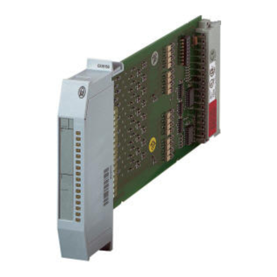
About the cards Setup The scope of delivery of all cards includes the plug connector housing with a plug-in screw terminal and the label strip with a plexiglass cover. The plug connector is required for the card to function in the PS416 automation system. Figure 1-1: Setup of the digital input/output cards... - Page 12 Setup Pos. PS416-INP-400/401 PS416-OUT-400 PS416-OUT-410 Cable exit (bottom standard, top as an option) Locking mechanism – Operating mode – selector switch Code switch Marking strip – Short-circuit indication for central disconnection module (ZAA) – Reset button Connector plug – Connection terminal for “ZAA” Plug-in screw terminal Procedure The following basic instructions ensure a correct...
- Page 13 About the cards 2. Setting the mode The setting of the operating mode selector switch determines how the card will react in the event of a short-circuit. This function is only implemented with the PS416-OUT-400 and is described in the chapter “Hardware Configuration”.
- Page 14 Setup Figure 1-2: Marking strip for PS416-INP-400/401 Status display 5. Inserting the card in the rack The voltage-free card can now be inserted in the rack. The card is fastened or removed via the locking mechanism . The cards are all inserted and removed in the same way (see chapter “Installation”...
- Page 15 About the cards 6. Fitting the plug connector The connection plug is plugged in. This concludes the installation of the card (see chapter “Installation” on page 1-13).
-
Page 16: Engineering
Engineering General The relevant regulations for safety and prevention of engineering notes accidents must be observed. Machines and systems which are fetted with the PS416 are subject to the relevant EN-, IEC-, VDE regulations. Emergency OFF devices acc. EN 60204/IEC 204 (VDE 0113) must always be active in all operation modes of the controller. - Page 17 Avoid long, parallel runs of cables with differing power ratings. You can find further information on this subject in the Moeller Manual “Electromagnetic Compatibility of Automation Systems (EMC)” (TB27-001-GB) and “EMC-Engineering Guidelines for Automation Systems PS4/PS416” (AWB27-1287GB).
-
Page 18: Example
Example Example 24 V Figure 1-3: Engineering guideline for voltage supply cables of the output card Ferrite ring 1-11... - Page 19 1-12...
-
Page 20: Installation
Installation Inserting and removing cards Note The PLC must be disconnected from the power supply before you insert or remove cards. Otherwise, voltage peaks at the bus plug can damage the card. Inserting cards Insert the card into any slot of the rack to the right of the power supply PS416-CPU-4x0 or the SUCOnet K card PS416-NET-400. - Page 21 Installation Figure 1-4: Inserting and removing cards 1-14...
-
Page 22: Screw Terminal Inserting-/Removing
Screw terminal Inserting-/Removing Screw terminal When connecting the cards to stations, you are Inserting-/Removing recommended to remove the screw terminal from the housing of the connection plug. The following figure illustrates how the screw terminal is inserted and removed. Figure 1-5: Inserting and removing the plug-in screw terminal 1-15... -
Page 23: Inserting And Removing The Marking Strip
Installation Inserting and removing The marking strip can be removed from the housing the marking strip of the connection plug very simply. Figure 1-6: Inserting and removing the marking strip 1-16... - Page 24 Contents 2PS416-INP-400/-401 1 Engineering Connecting the stations Power supply 2 Hardware Configuration Setting addresses 3 Software Configuration Configuring cards Setting card parameters 2-10 4 Operation 2-13 Function 2-13 Software addressing 2-14 5 Test/Commissioning/ Diagnostics 2-17 LED display 2-17 Sucosoft S40 2-18...
-
Page 26: Engineering
Engineering Connecting the Connections are made to the stations by means of stations the plug-in screw terminal in the connector plug housing: Remove the connector plug housing from the card. Remove the plug-in screw terminal. Wire the plug-in screw terminal according to the wiring plan. -
Page 27: Power Supply
Engineering The second GND connection is the continuation of the GND signal. Use wire diameters of 0.75 mm for the signal cables. Lock the plug-in screw terminal in the connector plug housing and push the cables through the underside of the housing. You can push the cables through the top if neces- sary. -
Page 28: Hardware Configuration
Hardware Configuration Setting addresses In order for the digital input cards to be addressed, each card must be assigned a separate address. The addresses are assigned with the coding switch on each card (see table 2-1 on page 2-6). This address assigns to each card a special range in the central unit. - Page 29 Hardware Configuration Table 2-1: Address coding for the PS416-INP-400/-401 Card address Input byte 0.0 to 0.7 1.0 to 1.7 2.0 to 2.7 3.0 to 3.7 4.0 to 4.7 5.0 to 5.7 6.0 to 6.7 7.0 to 7.7 8.0 to 8.7 9.0 to 9.7 10.0 to 10.7 11.0 to 11.7...
- Page 30 Setting addresses The positions of switches 7 and 8 do not matter. 2 3 4 5 6 7 Figure 2-2: Coding switch set for Address 4 Example The following figure illustrates a sample assignment of a rack with input and output cards. It shows how the marked input cards are addressed.
-
Page 32: Software Configuration
Software Configuration Configuring cards The digital input cards are configured in the Device Configurator of the Sucosoft S40. Figure 2-4: Device Configurator... -
Page 33: Setting Card Parameters
Software Configuration The following entries are made in the fields: Line: Number of the network line (0 = Basic unit; 1 to 9 = Expander rack) Rack/Station: Number of the rack (0 = Basic unit; 1 bis 30 = Expander rack) Slot/Module: Slot number in the rack. - Page 34 Setting card parameters Example A rack contains seven digital input cards, to which you assigned the addresses 0, 2, 4, 6, 8, 10, and 12 with the coding switch. The highest available input bytes are thus IB 12 and IB 13 (see Table 2-1 on page 2-6).
- Page 35 2-12...
-
Page 36: Operation
Operation Function The digital input cards are the interface between the input level and the processing level. In order to improve the reliability of the control system, the internal bus logic isolates the DC signals from the process by means of optical couplers. There is an LED for each input, which displays the signal status. -
Page 37: Software Addressing
Operation Software addressing After you have configured the card in the Device Configurator (see chapter “Software Configuration”), you can define the inputs using the Sucosoft S40 Editor and scan them with the IL Editor in bit, byte or word format. The following specifications are required to address the inputs: Operand: I Data type: Bit, Byte, word, double word... - Page 38 Software addressing I12.0 IB12 2 3 4 Slot I12.7 IW12 I13.0 I.10 I.11 Adr. 0 2 4 6 8 10 IB13 I.12 I.13 I.14 I.15 I13.7 Figure 2-7: Bit, byte and word addressing for digital input card with address 12 Wordwise addressing addresses all 16 inputs of the PS416-INP-400/-401 simultaneously with one command:...
- Page 39 Operation Bytewise addressing addresses inputs 0 to 7 or 8 to 15 simultaneously. In this example, inputs 8 to 15 are addressed: Variable declaration: Input_Slave_IB13 AT%IB0.0.0.13:BYTE; END_VAR User program: LD Input_Slave_IB13 ST ... Bitwise addressing always addresses exactly one input of a card. In this example input I 15 (bit 7 of the most significant byte) is addressed.
-
Page 40: Test/Commissioning/Diagnostics
Test/Commissioning/Diagnostics LED display The front panel contains green LEDs, each of which indicates the status of one input. Figure 2-8: LED display on the card Reset button LED ZAA Status display LED lit: The input has the status “1”. LED off: The input has the status “0”. -
Page 41: Sucosoft S40
Test/Commissioning/ Diagnostics Sucosoft S40 You can scan the logical status of the card inputs in the Sucosoft S40 menu “Test and Commissioning”. You will find more information on this subject in the manual “Sucosoft S40 Programmiing Software – User Interface” (AWB2700-1305GB). 2-18... - Page 42 Contents 3PS416-OUT-400/-410 1 Engineering Connecting the stations Power supply 2 Hardware Configuration Setting addresses Defining the short-circuit behaviour 3-12 3 Software Configuration 3-15 Configuring cards 3-15 Setting the card parameters 3-16 4 Operation 3-19 Function 3-19 Software addressing 3-20 5 Test/Commissioning/ Diagnostics 3-25 LED display 3-25...
-
Page 44: Engineering
Engineering Connecting the Connections are made to the stations by means of stations the plug-in screw terminal in the connector plug housing: Remove the connector plug housing from the card. Wire the plug-in screw terminal according to the terminal connection diagram. Qx.0 Qx.1 Qx.2... - Page 45 Engineering +24V +24V Qx.0 +24V +24V Qx.1 Qx.2 +24V +24V Qx.3 Qx.4 Qx.5 Qx.6 +24V +24V Qx.7 +24V +24V Figure 3-2: Plug connector assignment for the PS416-OUT-410 For the PS416-OUT-410, the external 24-V-DC supply voltage must be supplied to the card via at least three cables.
-
Page 46: Power Supply
Power supply Power supply The rack’s internal bus supplies the cards with 5 V DC from the power supply card PS416-POW-4x0. An external 24 V DC voltage must be connected to the card to provide the output power supply. -
Page 48: Hardware Configuration
Hardware Configuration Setting addresses In order for the digital output cards to be addressed, each card must be assigned a separate address. The addresses are assigned with the coding switch on each card (see Table 3-1 from page 3-8). This address assigns to each card a special area in the central unit. - Page 49 Hardware Configuration Table 3-1: Address coding for the PS416-OUT-400 Card address Input byte 0.0 to 0.7 1.0 to 1.7 2.0 to 2.7 3.0 to 3.7 4.0 to 4.7 5.0 to 5.7 6.0 to 6.7 7.0 to 7.7 8.0 to 8.7 9.0 to 9.7 10.0 to 10.7 11.0 to 11.7...
- Page 50 Setting addresses The positions of switches 7 and 8 do not matter. 2 3 4 5 6 7 Figure 3-3: Coding switch set for Address 4 Example The following figure illustrates a sample assignment of a rack with input and output cards. It shows how the marked digital output cards are addressed.
- Page 51 Hardware Configuration Table 3-2: Address coding for the PS416-OUT-410 Card address Input byte S1 S2 S3 S4 S5 S6 S7 0.0 to 0.7 1.0 to 1.7 2.0 to 2.7 3.0 to 3.7 4.0 to 4.7 5.0 to 5.7 6.0 to 6.7 7.0 to 7.7 8.0 to 8.7 9.0 to 9.7...
- Page 52 Setting addresses Card address Input byte S1 S2 S3 S4 S5 S6 S7 30.0 to 30.7 31.0 to 31.7 32.0 to 32.7 33.0 to 33.7 34.0 to 34.7 The position of pole 8 does not matter. 2 3 4 5 6 7 Figure 3-5: Coding switch set for Address 4 Example The following figure illustrates a sample assignment...
-
Page 53: Defining The Short-Circuit Behaviour
Hardware Configuration Defining the short- The behaviour of the card in case of a short-circuit is circuit behaviour defined with the operating mode selector switch on the card. This setting is only possible on the PS416-OUT-400. The short-circuit behaviour of the PS416-OUT-410 is equivalent to Mode 1. - Page 54 Defining the short-circuit behaviour Mode 2: (switch in position ON/closed) In case of a short-circiut, the affected output is switched off for approx. 200 ms. Then, an auto- matic restart attempt is made. This repeats itself until the short-circuit is eliminated. The red LED displays a short-circuit until the Reset button is pressed as an acknowledgement.
- Page 55 Hardware Configuration PS416 24 V 24 V +24 V 13/I 14/Q Figure 3-8: Monitoring 24-V-DC output cards using the ZAA central disconnection module ZAA loop The “ZAA” central disconnection module is addressed when WI/WQ has a low resistance compared to 0 V, or when the loop between the connections WI and WQ is broken.
-
Page 56: Software Configuration
Software Configuration Configuring cards The digital output cards are configured in the Sucosoft S40 Device Configurator. Figure 3-9: Device configurator 3-15... -
Page 57: Setting The Card Parameters
Software Configuration The entries specifications must be made in the following boxes: Line: Number of the network line (0 = Basic unit; 1 to 9 = Expander rack) Rack/Station: Number of the rack (0 = Basic unit; 1 to 30 = Expander rack) Slot/Module: Slot number in the rack. - Page 58 Setting the card parameters Example Set the address 4 on one of several digital output cards as the highest address. Enter “4” in the dialog box “Parameters” for the highest available output byte address, irrespective of whether the card is a PS416-OUT-400 or a PS416-OUT-410.
- Page 59 3-18...
-
Page 60: Operation
Operation Function The digital output cards are the interface between the processing level and the output level. The output circuits are galvanically isolated from the internal logic by means of optocouplers. Fuses or electronic fuses protect the PS416-OUT-400 against over- loads. -
Page 61: Software Addressing
Operation Aislamiento Modo de potencial operativo +24 V Lógica Tecla de reinicio PS416 +24 V +24 V +24 V Codificación de dirección +24 V PS416-OUT-410 Figure 3-12: PS416-OUT-410 block diagram Software addressing After you have configured the card in the Device Configurator (see chapter “Software Configuration”), you can define the outputs using the Sucosoft S40 Editor and scan them with the IL Editor in bit, byte or... - Page 62 Software addressing Operand: I Data type: bit, byte, word, double word Line number: 1 to 9 (0 = Basic unit) Station number: 1 to 30 (in the basic unit = 0) Slot number: 0 Word or Byte number (word: 0 to 34; byte: 0 to 35) Bit number: 0 to 7 The general syntax rule is: Operand-data type-line-rack/station-slot/module-byte/word-bit...
- Page 63 Operation Example Yout want to read or write the outputs of a digital output card. The card is located in the basic unit (line 0, station 0). The address 12 was set on the card. Q12.0 QB12 Slot 2 3 4 Q12.7 QW12 Q13.0...
- Page 64 Software addressing User program: LD Output_Slave_QW12 ST.. LD.. ST Output_Slave_QW12 Bytewise addressing addresses outputs 0 to 7 or 8 to 15 simultaneously. In this example, outputs 8 to 15 are addressed: Variable declaration: Output_Slave_QB13 AT%QB0.0.0.13:BYTE; END_VAR User program: LD Output_Slave_QB13 ST..
- Page 65 3-24...
-
Page 66: Test/Commissioning/Diagnostics
Test/Commissioning/Diagnostics LED display The front panel contains green LEDs, each of which indicates the status of one output. Figure 3-14: LED display on the card Reset button LED ZAA Status display LED lit: The output has the status “1”. LED off: The output has the status “0”. -
Page 67: Sucosoft S40
Test/Commissioning/ Diagnostics Sucosoft S40 You can scan and force the logical status of the card outputs by means of the menu “Test and Commis- sioning” of Sucosoft S40. You will find more detailled information on this subject in the manual “Sucosoft S40 Programming software –... -
Page 68: Appendix
Appendix Technical Data PS416-INP-400/-401 Number of inputs Galvanic isolation between input and logic 5 V (bus) Terminal design plug-in screw terminal 1.5 mm Connector cross-section Display elements Ambient temperature 0 °C ... +55 °C Storage temperature –25 °C ... +70 °C Humidity class see page 4-4 Dimensions [D... - Page 69 Appendix On/Off delay INP 400 normally 3.0/3.0 ms INP 401 normally 0.2/0.3 ms Utilization factor Operating factor 100 % PS416-OUT-400/PS416-OUT-410 PS416-OUT-400 PS416-OUT-410 Number of outputs Output current 0.5 A 2.0 A Output for = 24 V Galvanic isolation between output and logic 5 V (bus) Terminal design plug-in screw terminal Connector cross-section...
- Page 70 Technical Data PS416-OUT-400 PS416-OUT-410 Input 24 V Tolerance +20 %, –15 % Residual ripple Reverse polarity protections present Mode 1 with start disable Short-circuit release Mode 2 without start – Short-circuit release disable Parallel connection of outputs max. 4 Indication of monitoring activation present active low 300 A...
- Page 71 Appendix Details for electromagnetic compatability (EMC) of automation devices Emitted interference DIN EN 55 011/22 Class A Noise immunityt DIN EN 61 000-4-2 Contact discharge 4 kV Air discharge 8 kV DIN EN 61 000-4-3 AM/PM 10 V/m Burst DIN EN 61 000-4-4 Line/Digital I/O 2 kV Analog I/O, Field bus...
-
Page 72: Index
Index General Hardware requirements ..........1-3 Inserting and removing cards ........1-13 Inserting and removing the screw terminal ....1-15 Inserting the screw terminal ........1-15 Marking strips ............... 1-6 Power supply ..............1-9 Removing cards ............1-13 Removing the screw terminal ........1-15 Setup, Procedure ............ - Page 73 Index Configuration PS416-INP-400/-401 ..........2-10 Device Configurator ............2-9 Input address, highest ........2-10, 2-11 LED display PS416-INP-400/-401 ..........2-17 Optical couplers ............2-13 Power supply PS416-INP-400/-401 ..........2-4 Setting card parameters Example PS416-INP-400/-401 ........2-11 Slot numberr ..............2-10 Syntax rule ..............2-14 Type ................2-10 Wiring plan PS416-INP-400/-401 ..........2-3 PS416-OUT-400/-410 Addressing...
- Page 74 Index Cable exit ..............3-4 Coding switch PS416-OUT-400 ............3-9 PS416-OUT-410 ............3-11 Coding table PS416-OUT-400 ............3-8 PS416-OUT-410 ............3-10 Connector assignment PS416-OUT-400 ............3-3 PS416-OUT-410 ............3-4 Defining the short-circuit behaviour ......3-12 LED display PS 416-OUT-400/-410 ..........3-25 PS416-OUT-400/-410 ..........
Need help?
Do you have a question about the PS416-INP-40 SERIES and is the answer not in the manual?
Questions and answers