Table of Contents
Advertisement
Quick Links
Advertisement
Table of Contents

Summary of Contents for 16XEIGHT SD2IEC evo2
- Page 1 SD2IEC evo² Installation Instr uctions Revision E3b 6xEight...
- Page 2 Fragen oder Anregungen zu unseren Geräten selbstverständlich gerne zur Verfügung. Sie erreichen uns per e-Mail unter info at)16xeight.de Oder über das Kontaktformular auf unserer Homepage unter www.16xeight.de Für den Einbau und die Inbetriebnahme dieses Bausatzes sind Fachkenntnisse der Elektrotechnik sowie entsprechende handwerkliche Fähigkeiten erforderlich.
-
Page 3: Installation
Installation 1.1 Introduction Read these instructions carefully before starting the installation of the SD2IEC in your computer. Familiarise yourself with the connections and select a suitable location from which to perform the installation. Tools needed: • Phillips Screwdriver • File •... - Page 4 Installation Switch off your C64 and any attached devices and disconnect it from all cables. Turn the C64 on its top and remove the three case screws at the front edge. Turn the C64 back over and open it carefully by lifting the housing to the front edge under the keyboard. Take care that the locking lugs on the rear side of the case do not break.
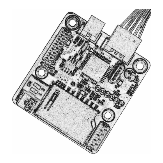
- Page 5 The DiskChange and Reset buttons can now be installed, if desired, by using the supplied cable and connecting the corresponding wires to the CTRL interface on the SD2IEC board as shown below. Make sure that the unused wires are carefully isolated to ensure that the no short circuits can arise! Fig.
-
Page 6: Functional Test
Commissioning Functional Test First, a function test should be carried out to ensure that the SD2IEC has been properly connected to the C64. Place a FAT formatted SD card into the SD2IEC. After the C64 has been switched on, at the flashing cursor type LOAD "$", 8 <return> The contents of the SD card should be listed on the screen. -
Page 7: Troubleshooting
TROUBLESHOOTING In the table below you can find common errors and their causes which will help to eliminate problems. If the problem is not rectified after following the remedies listed, please get in touch with us. Symptom Cause Remedy LED does not light up, the connected display re- mains dark and attempting to load the directory Check connections from the SD2IEC to the C64, No supply voltage to SD2IEC. - Page 8 ANNEX A The tables below show the pin assignments of the SD2IEC interface. IEC / POWER Pin Wire Colour Signal 1 Black Ground (GND) 2 Brown +5V Supply Voltage (VCC) 3 Red IEC-ATN 4 Orange IEC-DATA Fig. A.1 5 Yellow IEC-CLOCK CTRL Pin Wire Colour Signal...
Need help?
Do you have a question about the SD2IEC evo2 and is the answer not in the manual?
Questions and answers