Table of Contents
Advertisement
Quick Installation Guide
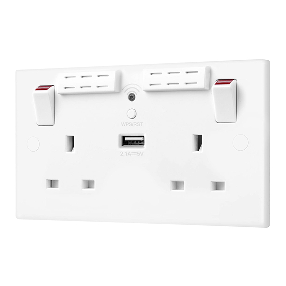
Wi-Fi Socket Range Extender N300 & Wi-Fi Socket Range Extender N300 + USB Charger
Positioning your Wi-Fi socket
Your Wi-Fi socket should be positioned half way between your router and the Wi-Fi dead-zone
Use the signal strength indicator on your mobile device to determine the mid-signal point
Choose a location away from Bluetooth devices and other household electronics (cordless
phone, microwave oven, baby monitor, etc.) to minimise signal interference.
Product overview:
Wi-Fi Socket Range Extender
SCREW
COVER
Wiring Instructions:
1
Power off
BEFORE COMMENCING WORK ALWAYS ISOLATE
THE POWER AT THE CONSUMER UNIT / FUSE BOX.
OFF
2b
New installation
KNOCK-OUTS
EARTH = Green & Yellow sleeving
NEUTRAL = Blue (Black pre Apr 04)
LIVE = Brown (Red pre Apr 04)
4
Complete the installation
1. Carefully position the accessory into the
mounting box, ensuring that no wires are
trapped between the plate and the wall and
secure with screws (do not over tighten) then
set screw covers in place (optional).
WI-FI SIGNAL ANTENNAS
LED WI-FI
INDICATOR
WPS/RST BUTTON
LIVE
2a
Replacing an existing socket (removal)
1. Unscrew the socket from the wall/mounting box.
2. Note the cable connections: There will generally be three different wiring
configurations, this illustration shows a single wire of each colour connected
to each terminal (there could be two or three wires of each colour connected
to each terminal) + an additional connection between the mounting box earth
terminal and the socket earth terminal.
3. Unscrew each terminal to release the wires.
EARTH = Green & Yellow sleeving
NEUTRAL = Blue (Black pre Apr 04)
LIVE = Brown (Red pre Apr 04)
OR
1. Install mounting box (metal or patress) for
either flush or surface mounting, ensuring
appropriate size of product. (mounting box to
be purchased separately)
2. Select the most suitable entry point of
the mounting box (knock-out) and route the
supply cable through.
3. Cables should be prepared so a sufficient
conductor length reaches the terminals. Strip
the ends of the individual conductors leaving
an adequate length bare to enter terminals.
2. Once installation has been completed
correctly, replace the fuse for the circuit,
switch the power back on at the consumer
unit and test.
ON
SAFETY WARNING
For your safety, this product must be installed in accordance with local Building Regulations. If in any doubt,
or where required by the law, consult a competent person who is registered with an electrical self-certification
scheme. Further information is available online or from your Local Authority. INDOOR USE ONLY.
Please read carefully and use in accordance with these safety wiring instructions. Before commencing any
electrical work ensure supply is switched off at the mains. Either by switching off the consumer unit or by removing
the appropriate fuse. Wiring should be in accordance with the latest edition of IEE regulations (BS 7671). To prevent
fire hazard always use cable of the correct rating, size & type for the application.
Any bare earth wires must be covered with the appropriate green/yellow sleeving.
Warning do not exceed the load rating of this device as stated on rear of the product.
If in doubt always consult a competent electrician.
ENVIRONMENTAL PROTECTION
Electrical products should not be disposed of with your general household waste. Some chemicals
contained within electrical products can be harmful to health and the environment. Only dispose of the
items in seperate colletion schemes which can cater for recovery and recycling of materials contained
within. Your co-operation is vital to ensure the protection of the environment.
Rear of Socket
L
N N
NEUTRAL
EARTH
TERMINALS
3
Wire up your socket
EARTH
NEUTRAL
USB Charger information:
2.1A USB port for charging mobile devices such as mobile phones, MP3 players and tablets.
2.1A 5V output from the USB output
• 2.1A is sufficient power output to charge the majority of USB products.
• The total output current achieved is dictated by specific device being charged and other external factors, such as the
quality of charging cable being used.
• Overload protection for connected devices.
Low energy stand-by mode
• When not in use the USB socket is in a low energy stand-by mode.
The USB circuits on this socket are designed to withstand insulation resistance tests at 500V. A reading of 0.4Ω +/-0.05
is typically caused by the USB socket
Note - The front surface of this product may become warm in use. This is normal and not cause for concern.
Wi-Fi Socket Range Extender
SCREW
HOLES
MOUNTING BOX
1. Line up the new socket to mounting box and
take note of where each terminal is located.
2. Connect each wire to the matching terminal.
(refer to key in step 2)
An earth connection should always be made
between the mounting box earth terminal and the
socket earth terminal.
Make sure no copper wire is exposed & that only
the bare end enters the terminal.
3. Tighten terminal screws securely.
LIVE
(do not over tighten)
+ USB Charger
2.1A
USB charging
socket
FROM SUPPLY
MOUNTING
BOX
EARTH
TERMINAL
Advertisement
Table of Contents

Summary of Contents for Bg Wi-Fi Socket
-
Page 1: Product Overview
Any bare earth wires must be covered with the appropriate green/yellow sleeving. Your Wi-Fi socket should be positioned half way between your router and the Wi-Fi dead-zone Warning do not exceed the load rating of this device as stated on rear of the product. -
Page 2: Wireless Setup
Wi-Fi socket setup instructions: Ensure that your Wi-Fi socket is connected to the power supply as per ‘Wiring instructions’ (see reverse). After the initial power up the LED indicator will illuminate with a solid blue light. After a short period of time the indicator will then start to blink and the product will then be ready for set-up... - Page 3 Wi-Fi Socket Beginners Guide...
- Page 4 Extender will increase the reach of your Wi-Fi signal. Range How do they work? By positioning the Wi-Fi socket halfway between your router and the area of poor reception, the range extender will relay the signal to further Wi-Fi Socket spread coverage.
- Page 5 Products in the range Wi-Fi Socket Wi-Fi Socket + USB FITS N300 25MM Mbps SINGLE BAND...
- Page 6 (Includes Wi-Fi Extender + USB) Plan It: things you will need Positioning your Wi-Fi Socket Your Wi-Fi socket should be positioned half way between Pliers your router and Wi-Fi dead-zone. Use the signal strength on your mobile device to determine the mid-signal point.
- Page 7 Gently ease the socket from the mounting box to show There will generally be three different wiring Alternatively, there could be two or three wires of each the wiring. configurations. This photo shows a single wire of each colour connected to each terminal. colour connected to each terminal.
- Page 8 • The Wi-Fi socket should show a solid blue LED, and • Click ‘Apply’. is now ready to use. WPS/RST • The Wi-Fi socket will show a solid blue LED, and is BUTTON • Your device will connect using your exisiting Wi-Fi now ready to use.
- Page 9 What are the minimum system retail high street retailers. Homekit/Google Home? requirements? Wi-Fi socket is designed to work solely as a 802.11 b/g/n 2.4GHz wireless router with I have fibre, not traditional ADSL range extender, it won’t connect to any home broadband internet connection.
- Page 10 If you are replacing a standard socket for a Yes, all of our wiring accessories and USB The power input/draw and output of the Wi-Fi socket, then no. BG Wi-Fi sockets sockets are ASTA approved. ASTA is a sockets when no device is connected is less...
- Page 11 Stuck? Confused? Contact our Technical Support team on: T: +44 (0)3300 249 279 or +44 (0)1952 238 128 E: technical.support@bgelectrical.co.uk Lines are open Mon - Fri (08:30 - 17:00)
Need help?
Do you have a question about the Wi-Fi Socket and is the answer not in the manual?
Questions and answers