Table of Contents
Advertisement
Quick Links
Advertisement
Table of Contents

Summary of Contents for Niveo Professional NWAC7000
- Page 1 MANUAL NWAC7000 Wireless Management Platform...
-
Page 2: Table Of Contents
Contents Chapter 1 Manual Introduction ....................... 4 Chapter 2:Product Introduction ......................4 2.1 Products description........................4 2.2 Products Properties ........................4 2.2.1Hardware Property ........................4 2.2.2 Software Property ........................5 2.3 Product Layout ..........................6 2.3.2 Rear Panel ........................... 7 Chapter 3 Configuration Guide ....................... - Page 3 4.9.1 Basic Status ........................... 35 4.9.2 LAN Status ..........................35 4.9.3 WAN Status ........................... 36 4.10 Help ............................36...
-
Page 4: Chapter 1 Manual Introduction
Chapter 2:Product Introduction 2.1 Products description NWAC7000 is a high performance WLAN controller, especially for Indoor and Outdoor wireless access points which set up in hotel or small-medium sized enterprise; It’s capable for managing all Access point, support AP auto-detection, AP status preview, AP configuration, MAC filtering, simultaneous AP software upgrade to provide high quality &... -
Page 5: Software Property
5 * 10/100/1000Mbps Gigabit Ethernet ports 2.2.2 Software Property The NWAC7000 detects and connects automatically to Wireless Access points. There is no need to configure each AP individually: complete centralized AP management utility Monitor remotely the real time , auto inspection of APs, automatic reboot functionality. -
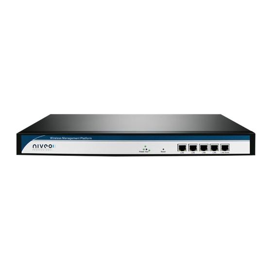
Page 6: Product Layout
If need to restore the NWAC7000 into factory default, pls do following procedure: Power on NWAC7000, use a pin to press and hold the reset button until all LED start flashing quickly from flashing slowly. Then release the button and wait for NWAC7000 to reboot to its factory default settings. -
Page 7: Rear Panel
2.3.2 Rear Panel Rear panel of NWAC7000 DC Jacket DC Jacket located on the right side of NWAC7000’s rear panel, input power should be ac power 100- 240V~ 50/60Hz 0.3A Anti-thunder ground connection: Please deploy ground connection to avoid lightening stroke, by copper core cable in yellow and green jacket;... -
Page 8: Chapter 3 Configuration Guide
In order to ensure a better effect of Web interface displays, it is recommended to adjust the display resolution to 1024 × 768 or more pixels. Operation Steps: A. Open IE browser,Input http://192.168.10.1/ in the address bar to login NWAC7000 Web management interface. B. Now please enter username and password. Factory default is:... -
Page 9: Chapter 4 Function Setting
Chapter 4 Function Setting 4.1 Device List Device list show the current wireless AP accessed by the NWAC7000, display the total quantity/Online/Offline Wireless AP connected to NWAC7000, Then Wireless AP’s name, IP address, MAC address, QTY of end users, Firmware version,... - Page 10 Let’s introduce following button one by one: Select: click the white box to make hook, to select this AP Blue balloon: Click it to set the AP’s Location and Device name, fill in the right info if needed, will be showed in Device list when Apply. Picture showed as follow: SN: Show how many AP access by this AC controller Location: show where the AP physical location is.
- Page 11 Config: click will show following picture: This picture, will show each AP’s status, Basic info, and advanced setting. If any changement you want to make, then Apply to finish. Device Status: show AP’s Model number, online time, MAC address, IP address, firmware info, channel, RF Power showed in above picture.
- Page 12 Wireless Basic: Mainly to setup the AP’s SSID, VLAN, Security. For the VLAN, the top networking should be with VLAN switch, and input the switch’s VLAN ID in the blank part. The VLAN ID range is 0~4094. Since this is a DUAL band AP, both bands need to be configurated. WlanDevice 1 is the 2.4Ghz band, Wlan deveice 2 is the 5.0GHz band...
- Page 13 Wireless Advanced: user can configure the AP’s mode, channel, Fragment Threshold, coverage threshold, Max Station...
- Page 14 Remark: For Fragment Threshold, RTS Threshold, Beacon Interval, Aggregation, ShortGI, Rev Option, we recommand to keed in default. Max Station, mean QTY of end users. 0 mean no limited. Coverage Threshold: Applicated in Roaming mainly, the working status showed as follow: Connected AP: Show how many pieces AP connected into this AC controller, and how many AP can access into this AC controller.
- Page 15 Search by IP: mean search the wireless AP by IP address, make hook in the white box, input IP address, then search. Search by MAC: mean search the wireless AP by MAC address, make hook in the white box, input MAC address, then search Batch Set: mean can configure the wireless AP’s data in batch.
-
Page 16: Device Group
4.2 Device Group Click Device Group at first, then will show New/Delete, Cick New, then configure the data in Wireless Basic and Wireless Advanced part; Pls note, this data will be applied for all the APs in this group. After finish all, set a group name, then Apply to finish. -
Page 17: Device Log
Add /Remove AP into group: Pls follow the steps showed in following picture: Please click : Then add APP to Wlan group device List Select APs and add these APs 4.3 Device Log Device Log show AP’s record, such as on line recording, offline recording, device configuration record. -
Page 18: Address Server
4.4 Address Server Through Address Server, to set server IP address, subnet mask; Server address Pool, main to assign IP address to the connected wireless AP, no need to specify the IP address for wireless AP manually when operation. Please use the correct IP address range. Server IP Address: modify the default AP address server’s IP address;... -
Page 19: Gateway
4.5 Gateway 4.5.1 LAN Setting LAN IP Setting: Set IP address for LAN Subnet mask Set Subnet mask for LAN DHCP Server DHCP server enable mean it will assign IP address for users. DHCP IP Count DHCP Client IP mean the IP address range assigned by DHCP Server. DHCP Lease Time The networking device get IP lease time from DHCP server. -
Page 20: Wan Setting
Click Gateway will automatically jump to the WAN settings as below; When select to intelligent gateway, NWAC7000 will have a router function, can work as a main router with Gigabit WAN/LAN port. It support Dynamic IP, Static IP; PPPOE; PPTP. -
Page 21: Cloud Setting
4.5.3 Cloud Setting Cloud Server Setting: Enable or Disable. Cloud Server: Input the cloud server’s IP address or domain name. Login Name: mean the account name in this cloud server. Contact information: input if you have. -
Page 22: Authentication
How to make NWAC7000 work with your authentication server: Gateway ID: Mean Gateway’s MAC address. In this part, our NWAC7000 should work in Intelligent Gateway, mean this ID is the MAC of NWAC7000. Web server name: this name is from server supplier, can fill or not fill. Take our cloud Platform for example: input wifidog in this part. - Page 23 MAC white list: User with MAC address in MAC white list can access into Internet directly, no need authentication. Add white MAC: Input the MAC address in blue part, or scan the MAC address, then click add MAC. Delete White MAC: click this button to delete it.
- Page 24 When choose Local Authentication in Authentication part, then Apply; please upload the pictures should show to end users. The step showed as following picture.
-
Page 25: Firewall
4.6 Firewall 4.6.1 IP/Port Filtering P4-6-1 IP/Port Filtering IP/Port forwarding enabled, router will limited the data forwarding according to the filtering rule. If the filtering rule is [refuse] , then the router will refuse to forward the data in accordance with filtering rule.; If the filtering rule is [allow], the router will forward the data in accordance with filtering rule. -
Page 26: Mac Filtering
4.6.2 MAC Filtering MAC Filtering Enabling Mac filtering, router will restrict data forwarding based on the selected filtering rules; When selected Close, router will decline the pointed incoming data; When selected as Open, then router will allow the pointed incoming rules; Mac address Set up rules in mac address, users can click Searching Mac Address from the clients in routers, or can set up the mac address manually;... -
Page 27: Port Forwarding
4.6.4 Port Forwarding Port forwarding Port forwarding is to forward data from one port to another port, enabling external users have access to an internal private IP in LAN, from an external triggered NAT router ; Rule Type Set up rule type, which have specific port number; Rule name Port forwarding rule name LAN IP... -
Page 28: Dmz Settings
4.6.5 DMZ Settings DMZ is short for demilitarized zone; It’s a compartment between security zone and non- security zone, in order to solve the problem of external network cannot access into internal server after firewall installation; This DMZ zone is a small network zone between external and internal network;... -
Page 29: Management
4.8 Management 4.8.1 System management Backup Save the configuration files to your computer Restore Using the saved configuration file recovery configuration Restore default Restore the factory default settings, please press this button Reboot Reboot the system... -
Page 30: Dns
4.8.2 DNS Enable or disable DNS... -
Page 31: 3Qos
4.8.3QoS Status Enable or Disable QoS function Upload Set up total uploading bandwidth Download Set up total downloading bandwidth IP Address Range Set up IP range of bandwidth MAC address Set up bandwidth control by mac address, user can choose it from Scan MAC, or setup by manual. -
Page 32: User Management
4.8.4 User management User Name Reset new log-in user name Password Reset new log-in password Confirm Password Comparison to new password, to confirm user input password correctly in two times 4.8.5 Device Log Status Enable or Disable to show system log Remote Log Service To decide whether send System log into some pointed remote server synchronously;... -
Page 33: Upgrade Firmware
4.8.6 Upgrade Firmware This feature allows the device firmware upgrade. Noted:Upgrading software may cause system outage, In the process of upgrading the firmware, do not power off, otherwise it may damage the AC controller! -
Page 34: System Time
4.8.7 System Time Synchronization with the host Synchronization time with connected PC and router Status Enable or Disable NTP NTP Server Select the server time synchronization Custom NTP Server Setting user-defined synchronization server IP address Time Zone Setting the router’s time zone... -
Page 35: Device Status
4.9 Device Status 4.9.1 Basic Status Show NWAC7000’s firmware version, hardware version, system uptime. 4.9.2 LAN Status LAN Setting Show NWAC7000’s LAN IP, DHCP server status and MAC address... - Page 36 4.9.3 WAN Status WAN Setting It shows NWAC7000’s WAN status, Connect Type, WAN IP, Subnet Mask, Gateway IP, DNS and MAC info. 4.10 Help If you meet with problem in understanding on above info, click help, then will pop up one...
- Page 37 Appendix A Product SPEC Item Parameter Standard Protocol IEEE 802.3、IEEE 802.3u Default: 200pcs, Max: 300pcs QTY of manageable AP MT7621, 880MHz FLASH 128Mb DDR3 DDR3 4096Mb Power Consumption < 5W Interface LAN port Four 10/100M/1000M RJ45 port(Auto MDI/MDIX) LAN/WAN port 1 LAN/WAN port,Default is LAN port, WAN port when open WAN mode Power Adapter...