Table of Contents
Advertisement
Advertisement
Table of Contents

Summary of Contents for Mercedes-Benz WICK 375
-
Page 3: Table Of Contents
FUEL CONNECT ASSEMBLY .................................... 23 5.12 CUT-OUT SWITCH RETROFIT KIT (71W37-COR) ............................23 5.13 BASIC WIRING / CUT-OUT SWITCH ................................24 WINTER STORAGE ........................................25 WARRANTY FOR WICK 375™ WATER PUMP ..............................26 COVERAGE ..........................................26 REMEDIES ..........................................26 EXCLUSION ..........................................26 Oct 2015... -
Page 4: General Descriptions
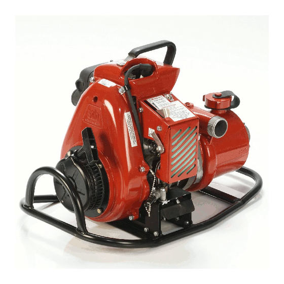
ABOUT THE WICK 375™ The WICK 375™ is the culmination of modern pump and engine design resulting in unsurpassed performance that will prove to be the future standard of portable fire pumps. The 10 HP, 210cc modern 2-stroke Solo engine is coupled to a detachable 4-stage foam-compatible pump using a one piece stainless steel clamp. -
Page 5: Operating Instruction
2.3.3 OTHER STARTING CONDITIONS When starting a new Wick 375 , or if the unit ran out of fuel, the primer bulb should be pressed until fuel can be seen inside the transparent tube under the carburetor. Follow normal starting procedures. -
Page 6: Shutting Down The Engine
ELECTRONIC LOSS OF PRIME HIGH SPEED CUT-OUT SWITCH The Wick 375™ is equipped with a patented "Electronic Cut-Out Switch" to prevent damage to the unit from loss of prime For instance, should a substantial amount of air enter the suction side of the pump, the engine will increase in speed and at over 7300RPM the cut-out switch will stop the engine, then automatically reset after 3 seconds. -
Page 7: Maintenance
MAINTENANCE AIR CLEANER Under ordinary operating conditions, the air cleaner should be cleaned daily. However, under extremely dirty conditions, more frequent cleaning is recommended. To clean the air cleaner, remove nut on intake housing, remove foam filter, brush off large debris, rinse in mineral spirits until clean, squeeze out remaining liquid and reinstall. Ensure backup screen is installed next to carburetor before installing foam. -
Page 8: Pump Disassembly
PUMP DISASSEMBLY For illustrative purposes refer to drawing in section 5.5 Remove the 6 Bearing Retaining Screws (17) located under the Drive Collar (8) Remove Screw (23) and Shaft Nose (22) from the suction end of the shaft. Remove the 8 Screws (14). The Suction Cover(6) can now be pulled off {use Puller tool, 79T-1207}. Using a small screw driver (or pick), pry tab of Lock Washer (21) from Shaft Nut (12). -
Page 9: Pump Assembly
PUMP ASSEMBLY Note: Inspect all components for wear, damage or corrosion. Replace components as required. Always use new "O" Ring Seals. Place Body (1) on smooth surface or {use Shaft fitting base, 79T-1965) to protect the body from damage, then press in the Rotary Seal (11) into Body (1).It is important that it be installed correctly, if leakage or damage to the body is to be avoided {use Seal installation tool, 79T -1963}. -
Page 10: Storing Motor
STORING MOTOR The following steps should be taken to prepare your engine for storage. Disconnect fuel line. Start engine and allow to run until it stops from lack of fuel. This will use up all the fuel in the carburetor and prevent the formation of deposits due to evaporation of fuel. Drain all fuel from the gasoline tank. -
Page 11: Troubleshooting
TROUBLESHOOTING CAUSE RECOMMENDATION Engine fails to start. Stop switch off. Turn to the ON/RUN position. No fuel in tank. Fill tank. Gasoline shut-off closed. Open shut-off valve. Fuel line or fuel tank screen clogged. Clean fuel line and screen. Flooded. Disconnect fuel line and open throttle full with choke open, then crank engine to start, reconnect fuel line and throttle back to idle. - Page 12 Insufficient oil in fuel mixture. Mix fuel as shown in starting instructions. Air flow obstructed. Clean flywheel and cylinder fins and screen. Improperly adjusted high speed mix screw. Adjust, see section 2.6. Blocked Filter inline or inside carburetor Change inline filter or dismantle carburetor and clean screen Engine noisy or knocking.
-
Page 13: Parts List
PARTS LIST ENGINE PARTS... - Page 14 ITEM PART NO. DESCRIPTION QTY/ASSY 71W37-1976B Muffler 72PSO10-0010138 F.H. Screw 18.5 ft-lb 72PSO10-0034115 Tension washer 71W37-1321 Exhaust Gasket 72PSO10-2043119 Air guide plate, exhaust side 71W37-2164 Intake Gasket 72PSO10-2043118 Air guide plate, carb side 72PSO10-0062229 O-Ring - Intake 72PSO10-2300540 Manifold 72PSO10-0030131 Washer 72PSO10-0034115 Tension washer...
-
Page 15: Engine Motor Parts
ENGINE MOTOR PARTS... - Page 16 ITEM PART NO. DESCRIPTION QTY/ASSY 72PSO10-2100883 Crankcase 72PSO10-0015208 Stud bolt 72PSO10-0034128 Spring washer 72PSO10-0020109 Hex. Nut 15 ft-lb 72PSO10-0010225 F .H. Screw 72PSO10-0034114 Spring ring 72PSO10-0020102 Hex. Nut 10 ft-lb 72PSO10-0054177 Oil seal 72PSO10-0050118 Ball bearing 72PSO10-2200780 Crankshaft 72PSO10-0031251 Friction washer 72PSO10-0052167 Needle bearing 72PSO10-0055187...
-
Page 17: Carburetor
CARBURETOR... - Page 18 ITEM PART NO. DESCRIPTION QTY/ASSY 22.82 Venturi (mm) 71W37-CARB Carburetor (Complete) 71W37-CARB-SASK Carburetor (Complete) for Saskatchewan Government Kit-Repair (Incl. Needles, O-Ring, Screen, Gasket, 72PSO10-K20WGA Diaphragm) Repair Kit Ring - Screen Retainer 72PSO10-1673 Ring - Shaft Retainer 72PSO10-1675 O-ring - Needles 72PSO10-21199 Cover-Metering Diaphragm 72PSO10-213027...
-
Page 19: Carburetor Adjustement Screws
CARBURETOR ADJUSTEMENT SCREWS... -
Page 20: Pump End Assembly
PUMP END ASSEMBLY ITEM PART NO. DESCRIPTION QTY/ASSY 79W128 Pump Body 79W126 Distributor 79W129 Distributor 79W127 Impeller 79W1211 Impeller 79W1212A Suction Cover 79W122C Shaft Assembly 79W123 Retainer 79W124AS Drive Bushing 78ORI-017N O-RING SEAL 79W1248 Bearing 79W1228T Seal 79W1250 79W1240 Bushing 78SF042809S Screw 79W1226... -
Page 21: Cover Assembly
COVER ASSEMBLY ITEM PART NUMBER DESCRIPTION QTY/ASSY 71W37-1926A Spark Plug Cover Machine 78STC0620MS Stud Self Clinching M6 X 20 78STC051820P Stud Self Clinching 5/16-18 NC 71W37-1314S Handle (Includes Rubber) 78SM0616MPO Screw - Use Loctite 242 on Rear Screw 78NL06MP Locknut 7.5 ft-lb 78WT06MP Lockwasher 71W37-1306... -
Page 22: Hardware Assembly
HARDWARE ASSEMBLY ITEM PART NUMBER DESCRIPTION QTY/ASSY 78SC0812MP Cap Screw M8 X 12 HEX. HD. 18 ft-lb 78SC0830MP Cap Screw M8 X 30 HEX. HD. 18 ft-lb 78SC0625MP Cap Screw M6 X 25 HEX. HD. Use Loctite 242 10 ft-lb 78SC0612MP Cap Screw M6 X 12 HEX. -
Page 23: Throttle Lever Assembly
THROTTLE LEVER ASSEMBLY ITEM NO. PART NO. DESCRIPTION QTY/ASSY 71W37-1301 Throttle Lever 78NL0518P Locknut 78WF0510P Washer Plain 5/16 78WS08MP Washer Spring Tension 5/16 78WF050901 Washer Fibre 5/16 71W37-1979 Detent Spring 71W37-1318 Link Throttle... -
Page 24: Filter Box Assembly (Pt. No. 71W-1985A Does Not Include Items 10, 11, 12)
Washer Spring 78WF040801 Washer Fibre 1/4 71W37-1319 Link Choke 71W37-1317 Filter Box Machined, Painted 78STC102412P Stud Self Clinching 10-24 NC AIR FILTER FOR WICK 375™ 71W37-1304A 71W37-2162 Filter Cover 71W37-1325 Filter Support Screen 71W37-1320 Filter Box Gasket 78NW1024L Wingnut #10-24 Nylon Insert... -
Page 25: Engine / Frame Mounting
5.10 ENGINE / FRAME MOUNTING ITEM NO. PART NUMBER DESCRIPTION QTY/ASSY 78SC0830MP Cap Screw M8 X 30 HEX HD. 18.5 ft-lb 78SCO820MP Cap Screw M8 X 20 HEX HD. 18.5 ft-lb 78NL0420P Locknut 1/4-20 Nylon Insert 10 ft-lb 78WF0518P Washer Plain 5/16 ID X 1 1/4 OD. 78WL05P Lockwasher 5/16 78WL04SS... -
Page 26: Fuel Connect Assembly
5.11 FUEL CONNECT ASSEMBLY ITEM PART NO. DESCRIPTION QTY/ASSY 78STC0630MS STUD SELF CLINCHING M6 X 30 78SC0612MP CAP SCREW M6 X 12 9 ft-lb 78NL06MP LOCKNUT M6 9 ft-lb 78WT06MP LOCKWASHER M6 78WF04P FLAT WASHER 1/4" 70FLPFLFV-M FUEL LINE FEMALE VALVE FITTING - MERCURY 70FLPFLMV-M FUEL LINE MALE VALVE FITTING - MERCURY 78FBP0404MELB... -
Page 27: Basic Wiring / Cut-Out Switch
5.13 BASIC WIRING / CUT-OUT SWITCH Figure 1 # 78E-COEN... -
Page 28: Winter Storage
WINTER STORAGE Make sure all pump ends, sprinklers and hoses are well drained. Disconnect pump end unit and rotate in several directions to remove as much water as possible. Add one cup (¼ litre) of antifreeze/glycol through the discharge end of the pump end unit ... -
Page 29: Warranty For Wick 375™ Water Pump
This warranty does not cover parts or accessories not supplied by Mercedes Textiles Ltd. or damage incurred through the use of such parts and accessories. This warranty shall not apply to the Wick 375 ™ pump when used in a manner that Mercedes Textiles regards as an unusual or unapproved operation.
Need help?
Do you have a question about the WICK 375 and is the answer not in the manual?
Questions and answers