Table of Contents
Advertisement
FSG 70
VHF/AM COM
TRANSCEIVER
118.000 ... 136.975 MHz
FSG 71M
VHF/AM COM
TRANSCEIVER
118.000 ... 136.975 MHz
Installation & Operation
applies for FSG 70, article no. F10002
applies for FSG 71M, article no. F10003
Before installing and operating the radio,
read this manual thoroughly, please!
Please observe the Safety Information!
Document No.
Revision No.
Date/Issue
Avionics Division
Erpftinger Strasse 36 « D-86899 Landsberg « Germany
Telephone +49 8191/3351-0 « Fax +49 8191/3351-49
e-mail: firma@dittel.com
Manual
Keep for further use!
027.HB.00E
(Reprint) 1
July 1998
« Internet: http://www.dittel.com
Advertisement
Table of Contents

Related Manuals for Walter Dittel FSG 70


Summary of Contents for Walter Dittel FSG 70
- Page 1 VHF/AM COM TRANSCEIVER 118.000 … 136.975 MHz Installation & Operation Manual applies for FSG 70, article no. F10002 applies for FSG 71M, article no. F10003 Before installing and operating the radio, read this manual thoroughly, please! Please observe the Safety Information! Keep for further use! Document No.
-
Page 2: Warranty - Copyright - Service
+49-8861 / 1739 Fax: +49-8861 / 1590 took over all repair work of airband radios of Walter Dittel GmbH, Luftfahrtgeraetebau, Erpftinger Stasse 36, D-86899 Landsberg am Lech, Germany. The offered services of company LANG include all repairs, overhaul, maintenance and inspection according to the regulations of the German Federal Aviation Authority (Luftfahrtbundesamt, LBA). -
Page 3: Table Of Contents
Transmitter Electrical Data....................2-5 2.4.4 Additional features........................ 2-5 2.5 Units and Accessories supplied ...................2-6 2.6 Accessories required, but not supplied.................2-6 2.7 Summary of the FSG 70-System .................2-7 Section III, Installation....................3-1 3.1 General ........................3-1 3.2 Pre-installation Check ....................3-1 3.2.1 Matching the Microphones ....................3-2 3.2.2... -
Page 4: List Of Illustrations
Location of Audio Sidetone Control and Microphone Gain Control..........3-2 Test Set-up, Envelope Detector ....................3-3 Deviation of Compass by FSG 70/FSG 71M depending on the Distance between Center of Compass and Contour of Transceiver ..................3-4 FSG 70, Dimensions, Installation Drawing..................3-5 FSG 71M, Dimensions, Installation Drawing................. -
Page 5: Section I, Safety Information
• Push-to-Talk keys may stick occasionally. Therefore, observe while transmitting the yellow TX LED at the FSG 70/71M. This TX LED must go off when releasing the PTT key. • Replace blown fuse only against correct type with specified nominal value. Investigate the cause. -
Page 6: Used Symbols
FSG 70/FSG 71M PERATION ANUAL W. Dittel GmbH Used Symbols In this manual the following symbols are used: DANGER! describes an immediate threatening danger! Failing to observe the note may cause death or heavy injuries! CAUTION! describes a special note for operation. Failing to observe the note may... -
Page 7: Section Ii, General Information
Introduction This installation and operation manual, 027.HB.00E, contains instructions and descriptions for application, installation and operation of the FSG 70 and FSG 71M 760- channel VHF aircraft transceivers of WALTER DITTEL GmbH's FSG 70-SYSTEM. The Service Manual 027.HB.10 contains detailed circuit description, repair instructions, alignment procedure, testing instructions, and a detailed Illustrated Parts List. -
Page 8: Brief Description
A non volatile electronic ten channel memory. This memory and its command controls make the only difference between FSG 70 and FSG 71M. The operational frequency of the FSG 71M unit is indicated by the LCD and may be selected in two modes on the... -
Page 9: Fsg 70-System Technical Data
Class C RTCA DO-157: Class 4 Performance category according to DO-160 A: D1/A/MNO/XXXXXXZBABZ The radios FSG 70 and FSG 71M fulfil the technical requirements of ICAO Annex 10, immunity against FM Broadcast Interference. 2 - 3 Reprint July 1998 Page... -
Page 10: Receiver Electrical Data
W. Dittel GmbH 2.4.2 Receiver Electrical Data Receiver type: Single superheterodyne Frequency range: 118.000MHz to 136.975MHz Number of channels (FSG 70): Number of channels (FSG 71M): 760, of which 10 frequencies may be free programmed and permanently stored Channel spacing: 25kHz Sensitivity: ≤1.0µV for 6dB (S+N)/N, 50 Ohms, mod. -
Page 11: Transmitter Electrical Data
W. Dittel GmbH 2.4.3 Transmitter Electrical Data Frequency range: 118.000 to 136.975MHz Number of channels (FSG 70): Number of channels (FSG 71M): 760, of which 10 frequencies may be free programmed and permanently stored Transmitter output: Min. 6 Watt into 50 Ohms at nom. voltage... -
Page 12: Units And Accessories Supplied
Battery power-pack 12Vdc/6.5Ah, if no on-board supply system f) Push-to-talk button for installation on control stick. g) To operate the FSG 70/FSG 71M on a 28-V on-board supply, a suitable voltage regulator must be used. h) 15-pole Plug, type DA-15S incl. shell, if no complete cable assembly is ordered. -
Page 13: Summary Of The Fsg 70-System
PERATION ANUAL W. Dittel GmbH Summary of the FSG 70-System In Table 2-1, the various types of VHF COM transceiver of the FSG 70 System are listed. The Part-No. is printed on the type plate of the respective transceiver. Frequency... - Page 14 FSG 70/FSG 71M PERATION ANUAL W. Dittel GmbH THIS PAGE INTENTIONALLY LEFT BLANK 2 - 8 Page Reprint July 1998...
-
Page 15: Section Iii, Installation
General This section contains instructions and suggestions for installing the FSG 70/ FSG 71M in an aircraft. Pre-installation Check Carefully remove the transceiver packing and save in case a claim has to be placed with the shipper. -
Page 16: Matching The Microphones
3.2.2 Audio Sidetone With the FSG 70/FSG 71M transceiver, a part of the modulation signal is fed to the headphone output as long as the transmitter is operated. The sidetone control (see Fig. 3-1) should be set so that the tone is audible, but not too loud. Please consider the ambient noise in the aircraft when adjusting. -
Page 17: Test Set-Up, Envelope Detector
FSG 70/FSG 71M PERATION ANUAL W. Dittel GmbH Dummy ¬ FOR TRANSMITTER CHECK Load ¬ VHF ¬ Modulation Oscilloscope ¬¬ FOR RECEIVER CHECK Wattmeter Analyser 50 Ω OS 250 A ¬ Bird Model 43 RACAL 9009 8 Watt Distortion ¬... -
Page 18: Mechanical Installation
3.3.1 Installation of the Transceiver The units of the FSG 70 System are rigid mounted behind the aircraft's panel. They fit into a standard 2¼" cut-out. If there is no suitable cut-out, one can be made following the drawing Fig. 3-4 or Fig. 3-5. -
Page 19: July 1998
FSG 70/FSG 71M PERATION ANUAL W. Dittel GmbH ∅ 4.5 47 ± ∅ 58 47 ± All dimensions in Millimeter Weight: 0.74 kg Fig. 3-4 FSG 70 Dimensions Installation Drawing 3 - 5 Reprint July 1998 Page... -
Page 20: Fsg 71M, Dimensions, Installation Drawing
FSG 70/FSG 71M PERATION ANUAL W. Dittel GmbH ∅ 4.5 47 ± ∅ 58 47 ± All Dimensions in Millimeter Weight: 0,8 kg Fig. 3-5 FSG 71 M Dimensions Installation Drawing 3 - 6 Page Reprint July 1998... -
Page 21: 3.3.3 Antenna Installation
3.3.3 Antenna Installation A conventional 50 Ohm vertically polarized COM antenna is required with the FSG 70/FSG 71M transceivers. The antenna must be able to radiate equally distributed RF energy without interference. For installation in an aircraft with a metal fuselage, we recommend our AV-529 antenna (part No. -
Page 22: On-Board Wiring
PERATION ANUAL W. Dittel GmbH On-board Wiring Figures 3-7 to 3-9 show possible ways of connecting the FSG 70/FSG 71M. 3.4.1 General Instructions for On-Board Wiring • Ensure good electrical contacts and interference suppression of all parts of the electrical system, e.g., alternator, ignition system, etc., also check for influences of vibration and corrosion. -
Page 23: Fsg 70/Fsg 71M, Hook-Up Diagram Without Intercom, 1-2 Dynamic Microphones
FSG 70/FSG 71M PERATION ANUAL W. Dittel GmbH COM Antenna DA-15S, Soldering Side PTT Key(s) in control stick (if required) Aircraft Speaker 30 W/4 Ω F10061 Antenna Coax FSG 70/FSG 71M RG 58 C/U COM Antenna To connect a Dyn. Microphone... -
Page 24: Fsg 70/Fsg 71M, Hook-Up Diagram Using Wire Harness F10029 1-2 Dynamic Microphones And Intercom
Unless otherwise noted, all wires #22 AWG (0.3 - 0.4 mm²) INTERCOM operation requires a microphone which provides audio OUT with the PTT key de-energized (not keyed). Built-in Automatic Circuit Breaker when using Walter Dittel Battery Power Supply A/N F10023. Length of pre-fabricated wire harness F10029: 3.2m / 10ft and coax antenna cable are not included in wire harness F10029 Fig. -
Page 25: Fsg 70/Fsg 71M, Hook-Up Diagram, 1-2 Standard Carbon Microphone/S And Intercom
If more than one AF source, isolation resistors 470 Ohm shall be installed. ¬¬¬ Fuse 2.5 Amp, semi time lag, or circuit breaker 2.5 Amp. Fig. 3-9 FSG 70/FSG 71M Hook-up Diagram 1 - 2 Standard Carbon Microphone/s and INTERCOM... -
Page 26: Connection Of The Microphones
NAV receiver are installed. The headphone output of the NAV unit can then be connected directly to the AF-Ext. input of the FSG 70/ FSG 71M and then be heard simultaneously from one common headphone or speaker (only during receive mode possible). -
Page 27: Illumination Of The Frequency Display
3.4.6 Illumination of the Frequency Display All transceivers of the FSG 70-System are equipped with an illumination of the frequency display. The lamp voltage is supplied via the aircraft's dimmer or directly from the aircraft supply. The lamp voltage is stamped on the type plate. If a 14Vdc- lighting should be connected to a 28Vdc aircraft supply, a 680 Ohm resistor (0.5 W) in... -
Page 28: Post Installation Check
FSG 70/FSG 71M PERATION ANUAL W. Dittel GmbH Post Installation Check 3.5.1 Testing on the Ground with the Engine Off After installing the unit, check all aircraft control movements to be sure no electrical cables interfere with their operation. Then measure the antenna matching between the RF jack of the unit and the antenna cable. -
Page 29: Section Iv, Operation
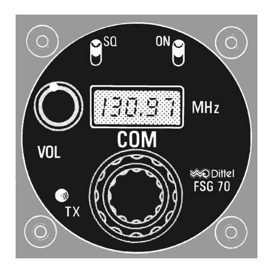
FSG 70/FSG 71M PERATION ANUAL W. Dittel GmbH Operation Section IV Control Functions STORE BUTTON SQ-SWITCH SQ-SWITCH ON-OFF-SWITCH ON-OFF SWITCH FREQUENCY DISPLAY FREQUENCY DISPLAY VOLUME VOLUME CHANNEL SWITCH INDICATOR INDICATOR kHz SELECTOR MHz SELECTOR kHz-SELECTOR MHz-SELECTOR SWITCH SWITCH SWITCH SWITCH Fig. -
Page 30: Operating Instructions
FSG 70/FSG 71M PERATION ANUAL W. Dittel GmbH Additional at FSG 71M Controls Description Function Readouts CHAN Rotary knob with 11 detents Knob fully clockwise: Channel selector Frequency free selectable by MHz- and switch kHz knobs. Knob on position 1 through 10: Recall or storage of channel frequencies. -
Page 31: Programming The Channel Frequency Memory (Fsg 71M Only)
(recommended date of change see separate tag on unit). Battery Check The FSG 70-System transceivers indicate low battery voltage by causing the frequency display to blink if the power supplied drops below 11 volts. When operating from battery: Depending on battery capacity and the duration of transmit operation, the following operating times may remain after blinking starts until the battery is fully exhausted. -
Page 32: Emergency Operation
When wired for this purpose, the volume of the external receivers is/are to be set so the signals can be understood, and distinguished one from another. The VOL control of the FSG 70/FSG 71M affects not the volume of the external units, and vice versa. 4 - 4... -
Page 33: Appendix A, Certificate
FSG 70/FSG 71M PERATION ANUAL W. Dittel GmbH Certificate Appendix A A - 1 Reprint July 1998 Page...