Table of Contents
Advertisement
96mm x 96mm Ramping Controller (1/4 DIN)
0600-0032-0000 Rev G
*0600-0032-0000*
April 2004
Series F4S/D
User's Manual
with Guided Setup and Programming
1241 Bundy Boulevard, Winona, Minnesota USA
Phone: +1 (507) 454-5300, Fax: +1 (507) 452-4507 http://www.watlow.com
Registered Company
Winona, Minnesota USA
$15.00
Advertisement
Chapters
Table of Contents

Related Manuals for Watlow Electric F4S Series


Summary of Contents for Watlow Electric F4S Series
- Page 1 Series F4S/D User’s Manual 96mm x 96mm Ramping Controller (1/4 DIN) with Guided Setup and Programming 1241 Bundy Boulevard, Winona, Minnesota USA Phone: +1 (507) 454-5300, Fax: +1 (507) 452-4507 http://www.watlow.com Registered Company Winona, Minnesota USA 0600-0032-0000 Rev G *0600-0032-0000* April 2004 $15.00...
- Page 2 About Watlow Winona Watlow Winona is a division of Watlow Electric Mfg. Co., St. Louis, Missouri, a manufacturer of industrial electric heating products since 1922. Watlow begins with a full set of specifications and completes an indus- trial product that is manufactured in-house, in the U.S.A. Watlow products include electric heaters, sensors, controllers and switching devices.
-
Page 3: Table Of Contents
Series F4S/D: Table of Contents Introduction Installation and Wiring Chapter 1: Introduction ....1.1 Chapter 11: Installation ....11.1 Chapter 2: Keys, Displays and Navigation . - Page 4 Safety Information in this Manual ç Note, caution and warning symbols appear throughout this book to draw your attention to important operational and safety information. A “NOTE” marks a short message to alert you to an important detail. A “CAUTION” safety alert appears with information that is important for protecting your Safety Alert equipment and performance.
-
Page 5: Introduction
Chapter One: Introduction Overview Watlow’s Series F4 1/4 DIN industrial ramping • 256 possible ramp steps in as many as 40 vari- controllers are easy to set up, program and operate able-length, nameable profiles in the most demanding ramp-and-soak-processing • six step types applications. -
Page 6: Sample Application: Environmental Testing
Sample Application: Environmental Testing with a Dual Channel F4 Using Multiple Inputs and Outputs Overview Andy, an engineer with the Ajax Testing Company, is running tempera- ture and humidity tests on navigation- al equipment. He wants to be able to control temperature and humidity in the environmental chamber, and moni- tor the temperature of the equipment... -
Page 7: Profile Programming
Main Page___________ Choose to Setup:____ Go to Profiles Digital Output8 Go to Setup Communications Go to Factory Custom Main Page 3. Customize and Name 2. Set up the F4 Andy customized the Main Page so he could After checking the navigation instructions tell the status of the digital outputs by glanc- in the user manual, Andy went to the ing at the controller's Lower Display (Setup... -
Page 8: Profile Programming
Setup Steps • If the Series F4 is an independent unit, start • If the Series F4 is already installed in a piece with Step 1 below. of equipment and the setup and profile pro- gramming functions are locked, proceed direct- •... - Page 9 Chapter Two: Keys, Displays & Navigation Displays and Indicator Lights ....2.2 Custom Main Page ......2.3 Keys and Navigation .
-
Page 10: Displays And Indicator Lights
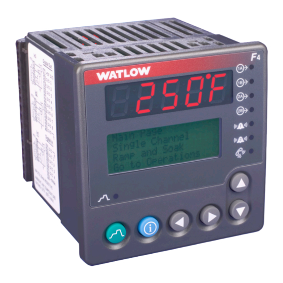
Displays and Indicator Lights Upper Display Displays Channel 1 actual process values during Active Output Indicator operation. Displays error Lights (Output status): information if errors occur. Lit when the corresponding controller channel output is active. (F4D shown) Lower Display Displays information about the setup, operation and programming of the controller. -
Page 11: Custom Main Page
Custom Main Page The first and central page on the Lower Display is sen information. (To do so, go to the Setup Page, the Main Page, which shows error messages, input, Custom Main Page Menu. See Chapter 5, Setup, output and profile status, and allows access to con- for instructions.) troller software (Go to Operations, Profiles, Setup The following parameters will appear by default on... -
Page 12: Keys And Navigation
Keys and Navigation Setup Page Main>Setup Choose to Setup System Analog Input 1 Think of this display as a window into the software table. You move around in the software using the following navigation keys: > Move Up/Increase , . < Move Down/Decrease Back Next Main Page___________... -
Page 13: Guided Setup
Guided Setup Main Page___________ Go to Operations Go to Profiles In most F4 menus, setup and programming tasks >Go to Setup are guided. For example, once you select Analog Input 1 on the Setup Page, all parameters neces- sary to configure that input are linked: Choose to Setup:____ >... -
Page 14: How To Enter Numbers And Names
How to Enter Numbers and Names Many parameters require users to enter a numeri- nized names, such as TOO HOT for an alarm, cal value. Alarms, digital inputs, digital outputs DOOR OPEN for a digital input and GLAZE 6 for and profiles can be customized with easily recog- a profile. -
Page 15: ˆ Information Key Answers Your Questions
ˆ ˆ Information Key Answers Your Questions There’s a wealth of information about features and 2. Press the ˆ key. The displayed information will parameters right in the Series F4 controller. Use assist you during setup and operation. When the Information Key to get this information. information takes more than four lines, the scroll bar will be filled or weighted at the end, 1. -
Page 16: Main Page Parameter Table
Main Page Parameter Table Modbus Register Range read/write Conditions for Parameter Description (Modbus Value) Default [I/O, Set, Ch] Parameters to Appear Main Page Main > Setup > Main Page Input x (1 to 3) Error Alarm x (1 to 2) Condition Autotuning Channel x (1 or 2) Parameter x (1 to 16) None... -
Page 17: Operations
Chapter Three: Operations Static Set Point Control ..... .3.1 Profile Control ......3.2 Alarm Set Points . -
Page 18: Chapter 4: Profile Programming
π Profile Control > ■ Start a Profile? The main purpose of the Series F4 is to control pro- ■ files for ramp-and-soak-processing applications. ▼ No ▲ Yes ■ The instructions below explain how to use an exist- ■ ■ ■ ■ ■ ■ ■ ■ ■ ■ ■ ■ ■ ■ ■ ■ ing profile. - Page 19 To Hold a Running Profile π Hold Profile:_______ 1. Press the Profile Key while running a pro- Don’t Hold file. The Profile Action Menu appears. >Hold 2. Choose to Don’t Hold, Hold or Terminate Terminate the profile. (Default is to Don’t Hold.) If you choose to hold the profile, the Main Page reap- pears, and the Profile Status message reads “Profile X holding.”...
-
Page 20: Alarm Set Points
✔ NOTE: Alarm Set Points PID Set 1 for Channel 1 and PID Set 6 for Channel 2 are used in the Static Set Point mode. The Series F4 includes two alarm outputs, which Autotuning Procedure can be programmed as process or deviation alarms. Autotuning cannot be initiated while a profile is Process alarms notify the operator when process running. -
Page 21: Multiple Pid Sets
Integral (Reset): Define the integral time in min- new set point without overshooting or approach- utes per repeat; define reset in repeats per minute. ing the set point too slowly. Set repeats per minute if units are U.S.; minutes For additional information about manual tuning per repeat if units are SI. -
Page 22: Cascade
Cascade Cascade Autotuning Procedure 1. Go to Setup Page, Custom Main Page Menu. Cascade control is available on the Series F4 con- Choose Tune Status 1 and Tune Status 2 to ap- trollers. For background information about cascade pear as 2 of the 16 parameters that can be dis- control, see the Features Chapter. -
Page 23: Sample Application
Sample Application: Environmental Testing, Running a Profile Andy presses the Profile Key π , moves the cursor to "MILSTD810D" on the Run Profile Menu, then Main Page___________ Go to Profiles Go to Setup Go to Factory presses the Right Key . -
Page 24: Troubleshooting Alarms And Errors
Troubleshooting Alarms and Errors Indication Probable Cause(s) Corrective Action Power • Displays are dead. • Power to unit may be off. • Check switches, fuses, breakers, interlocks, • Fuse may be blown. limits, connectors, etc. for energized condi- • Breaker may be tripped. tions and proper connection. - Page 25 Indication Probable Cause(s) Corrective Action Input Errors (Upper Display shows error code • Input is in error condition. • Check sensor connections. for input 1 only. Lower Display shows error message. Alarm Output Indicator is lit.) Upper [A-dLO] • Check sensor connections and sensor •...
- Page 26 Operations Page Map Autotune PID PID Set Channel 2 Channel 1 Autotune PID Set 6-10 Tune Off Proportional Band A PID Set 1 IntegralA / ResetA PID Set 2 DerivativeA / RateA PID Set 3 Dead Band A PID Set 4 Hysteresis A PID Set 5 Proportional Band B...
-
Page 27: Operations Page Parameter Table
Operations Page Parameter Table Modbus Register Range read/write Conditions for Parameter Description (Modbus Value) Default [I/O, Set, Ch] Parameters to Appear Autotune PID Main > Operations > Autotune PID Tune Off (0) Tune Off (0) Channel Active: Always (Channel 1). Channel x (1 to 2) Autotune Ch1 PID Set 1 (1) Active if controller is set to Dual... - Page 28 Operations Page Parameter Table Modbus Register Range read/write Conditions for Parameter Description (Modbus Value) Default [I/O, Set, Ch] Parameters to Appear Rate x (A or B) 0.00 to 9.99 minutes 0.00 minutes 1B Set Active if PID Units (Setup Page) 554 [1] (0 to 999) is set to U.S.
- Page 29 Operations Page Parameter Table Modbus Register Range read/write Conditions for Parameter Description (Modbus Value) Default [I/O, Set, Ch] Parameters to Appear Dead Band x (A or B) 0 to 30000 0 (0) 2B Set Active if Proportional Band is not 2505 2555 [6] (1 to 30000) set to 0 and one output is set to...
- Page 30 Operations Page Parameter Table Modbus Register Range read/write Conditions for Parameter Description (Modbus Value) Default [I/O, Set, Ch] Parameters to Appear Hysteresis x (A or B) 1 to 30000 3 (3) 1B Set Active if Proportional Band is set 2607 2657 [1] (1 to 30000) to 0 and one channel is set to Define the process...
-
Page 31: Operations Page Parameter Record
Operations Page Parameter Record Make a photocopy of this page and enter your settings on that copy. Name _________________________________________________ Date __________________________________________________ Operations Page PID Set Chan 1 Menu PID Set Chan 1 Menu PID Set 1 PID Set 1 PID Set 2 PID Set 2 PID Set 3 PID Set 3... - Page 32 Notes ■ 3 .16 Operations Watlow Series F4S/D...
- Page 33 Chapter Four: Profile Programming What is a Ramping Profile? ....4.2 Step Types .......4.2 Profile Plan Checklist .
-
Page 34: What Is A Ramping Profile
What Is a Ramping Profile? A ramp is a programmed change from one set point to another. A soak maintains the set point over a period of time. A profile is a set of instructions programmed as a sequence of steps. The controller handles the pro- file steps automatically, in sequence. -
Page 35: Profile Plan Checklist
Soak process value must arrive at or cross the specified value before the step proceeds. Soak maintains the set point from the previous Digital inputs must first be configured in the Setup step for a chosen time in hours, minutes and sec- Page as Wait for Events, with the condition to be onds. -
Page 36: How To Program A New Profile
How to Program a New Profile The Series F4 uses a question-and-answer format to prompt you to define the steps and step types of a new profile. Here’s how: Main Page___________ Go to Profiles Go to Setup 1.Go to the Profiles Page. Go to Factory Move the cursor to Go to Profiles (at the bottom of the Main Page), then press the Right Key . - Page 37 • how much time it will take to reach set point; • what the set point is; • which PID set to activate; and • whether you want a guaranteed soak. Enter Ramp Time:____ Continue defining step types until your pro- 00:00:01 (H:M:S) file is complete.
-
Page 38: How To Edit A Profile
How to Edit a Profile To change one or more parameters in any step of a profile, choose Edit Profile on the Profiles Page. 1. Go to the Profiles Page. Move the cursor to Go to Profile (at the bottom of the Main Page), then press . -
Page 39: User Profile Record
User Profile Record Copy this record and use it to plan profiles. Keep it with a Setup Page Parameter Record to document the controller’s programmed settings. Profile Name:__________________________________ Date Programmed: ____________________________ Programmed by: ______________________________ Controller checked by:__________________________ Step Step Date/Day, Wait Set Events Time... -
Page 40: A Sample Application
A Sample Application: Environmental Testing Programming a Profile To test its customers’ navigational equipment, Ajax Testing Co. selected a version of Military Standard Test 810D, which is often used to test navigational or Main Page___________ Go to Profiles Go to Setup Go to Factory other military equipment under hot, humid conditions. - Page 41 Step Step Date/Day, Wait Set Events Time Rate Guar. Jump to Step Repeats End Nmbr Type Time 1 2 3 4 5 6 7 8 H M S Pt 1 Pt 2 Soak Profile Step Ramp Time 1 sec. 88°F Soak Process1&2 1 sec.
-
Page 42: Frequently Asked Questions
Frequently Asked Questions About Profiles 1. Why should I check the Setup Page before 7. Why can’t I delete the End step? programming a profile? Because every profile must have an End step, and Complex, sophisticated profile control is possible this End step is programmed into the profile. - Page 43 Profiles Page Map Edit Profile Profile x (1 to 40) Create Profile Insert Step Name Profile Insert Before Step x Step x (1 to 256) Type Step x (1 to 256) Type (see below) Autostart Edit Step Date Step x (1 to 256) Type Autostart Time Date...
-
Page 44: Profiles Page Parameter Table
Profiles Page Parameter Table Modbus Register Range read/write Conditions for Parameter Description (Modbus Value) Default [I/O, Set, Ch] Parameters to Appear Autostart …>Edit Profile > Profile x (1 to 40) > Edit Step > Step x (1 to 256) > Autostart Step Date M/D/Y today’s date... - Page 45 Profiles Page Parameter Table Modbus Register Range read/write Conditions for Parameter Description (Modbus Value) Default [I/O, Set, Ch] Parameters to Appear 00:00:01 to 99:59:59 00:00:01 Active if Step is set to Ramp Time 4009 r/w [h] Time or Soak. [h] (0 to 99) 4119 Set the time in [m] (0 to 59)
- Page 46 Profiles Page Parameter Table Modbus Register Range read/write Conditions for Parameter Description (Modbus Value) Default [I/O, Set, Ch] Parameters to Appear Don’t Wait (0) Don’t Wait (0) Input Active if the selected Event Input Event Input x (1 to 4) 4013 r/w is Enabled.
- Page 47 Profiles Page Parameter Table Modbus Register Range read/write Conditions for Parameter Description (Modbus Value) Default [I/O, Set, Ch] Parameters to Appear PID Set … > Profile x (1 to 40) > Edit Step > Step x (1 to 256) > Ramp Time or Ramp Rate or Soak Step > PID Set PID Set 1 (0) PID Set 1 (0) 4046 r/w...
- Page 48 Profiles Page Parameter Table Modbus Register Range read/write Conditions for Parameter Description (Modbus Value) Default [I/O, Set, Ch] Parameters to Appear Idle Main > Profiles > Edit Profile > Profile x (1 to 40) > Edit Step / Step x (1 to 256) > Step > End > Idle Enter Channel 1 Idle Set Set Point 1 Low Limit 75 (75)
- Page 49 Chapter Five: Setup Setup Guidelines ......5.1 Parameter Setup Order ..... .5.1 Customizing the Main Page .
- Page 50 • the guaranteed soak band for each channel; After the initial configuration of the controller, the most frequent changes will be to profiles, alarm set • open-loop detection warnings on or off; and points and PID sets. The Setup Page is likely to be •...
- Page 51 Custom Main Page Parameter Record Make a photocopy of this page and enter your settings on that copy. Name ___________________________________________ Date ______________________________ Main Page Input 1 Error Will always appear if active: Input 2 Error Input 3 Error Alarm 1 Condition Will appear if active and Alarm 2 Condition set up to appear:...
- Page 52 Sample Application: Setup for Environmental Testing Analog Input 1 Main Page___________ Go to Profiles Go to Setup Go to Factory For greatest accuracy in measuring the chamber temperature, a re- sistance temperature detection (RTD) sensor has been wired to ana- log input 1.
- Page 53 Analog Input 2 Analog Input 3 The humidity sensor on analog input 2 was a process sensor using a 4 to A thermocouple (type J) sensor 20 mA signal, so Andy set the high end of the scale (20mA) for 100% and was adequate to measure the the low (4mA) for 0% relative humidity (rh).
-
Page 54: Chapter 5: Setup
Setup Page Map Alarm Output x (1 and 2) Name Alarm Type System Alarm Source Guar. Soak Band1 Latching Guar. Soak Band2 Silencing Current Time Alarm Hysteresis Current Date Alarm Sides PID Units Alarm Logic °F or °C Alarm Messages Show °F or °C Retransmit Output x (1 and 2) Ch1 Autotune SP... - Page 55 Setup Page Parameter Table Modbus Register Range read/write Conditions for Parameter Description (Modbus Value) Default (I/O, Set, Ch) Parameters to Appear System Main > Setup > System Guarantee Soak Band Decimal choice Band Active: Always (1). dependent: 1205 x (1 or 2) Active if controller is Dual Chan- 1212 1 to 30000, or...
- Page 56 Setup Page Parameter Table Setup Page Parameter Table Modbus Modbus Register Register Range Range read/write read/write Conditions for Conditions for Parameter Parameter Description Description (Modbus Value) (Modbus Value) Default Default (I/O, Set, Ch) [I/O, Set, Ch] Parameters to Appear Parameters to Appear Analog Input x (1 to 3) Main >...
- Page 57 Setup Page Parameter Table Modbus Register Range read/write Conditions for Parameter Description (Modbus Value) Default (I/O, Set, Ch) Parameters to Appear Altitude 0 to 2499 ft (0) 0 to 2499 ft 1902 r/w Active if Analog Input 2 Type is 2500 to 4999 ft (1) Wet Bulb-Dry Bulb.
- Page 58 Setup Page Parameter Table Setup Page Parameter Table Modbus Modbus Register Register Range Range read/write read/write Conditions for Conditions for Parameter Parameter Description Description (Modbus Value) (Modbus Value) Default Default (I/O, Set, Ch) [I/O, Set, Ch] Parameters to Appear Parameters to Appear Set Point High Limit Depends on sensor.
- Page 59 Setup Page Parameter Table Modbus Register Range read/write Conditions for Parameter Description (Modbus Value) Default (I/O, Set, Ch) Parameters to Appear Function Off (0) Off (0) Input Active: Always. 1060 Panel Lock (1) While a profile is running, the Select the digital 1062 Reset Alarm (2) controller will not recognize...
- Page 60 Setup Page Parameter Table Setup Page Parameter Table Modbus Modbus Register Register Range Range read/write read/write Conditions for Conditions for Parameter Parameter Description Description (Modbus Value) (Modbus Value) Default Default (I/O, Set, Ch) [I/O, Set, Ch] Parameters to Appear Parameters to Appear Alarm Output x (1 and 2) Main >...
- Page 61 Setup Page Parameter Table Modbus Register Range read/write Conditions for Parameter Description (Modbus Value) Default (I/O, Set, Ch) Parameters to Appear High Scale Low Scale +1 to 30000 High end of Output Active: Always. (maximum sensor sensor Set high end of cur- range) (Low Scale +1 range rent or voltage...
-
Page 62: Chapter 7: Communications
Setup Page Parameter Table Setup Page Parameter Table Modbus Modbus Register Register Range Range read/write read/write Conditions for Conditions for Parameter Parameter Description Description (Modbus Value) (Modbus Value) Default Default (I/O, Set, Ch) (I/O, Set, Ch) Parameters to Appear Parameters to Appear -100% to 100% 0% (0) 2072 r/w... - Page 63 Setup Page Parameter Table Modbus Register Range read/write Conditions for Parameter Description (Modbus Value) Default (I/O, Set, Ch) Parameters to Appear Custom Main Page Main > Setup > Custom Main Page P x (1 to 16) None (0) [1] Current Par.
-
Page 64: Calibration Offset
Setup Page Parameter Record Make a photocopy of this page and enter your settings on that copy. Name ___________________________________________ Date ______________________________ Setup Page System Menu System Menu Setting Setting Guar. Soak Band 1 Guar. Soak Band 1 Guar. Soak Band 2 Guar. - Page 65 Chapter Six: Features Inputs Calibration Offset ..... . .6.2 Filter Time Constant .....6.2 Set Point Low Limit and High Limit .
-
Page 66: Calibration Offset
Inputs/Outputs Calibration Offset The negative calibration offset will compensate for the difference Temperature Reading Calibration offset allows a device to compensate for between the sensor reading and from Sensor the actual temperature. an inaccurate sensor, lead resistance or other fac- tors that affect the input value. -
Page 67: Set Point Low Limit And High Limit
Set Point Low Limit and High Limit The controller constrains the set point to a value High Limit of selected Sensor Range between a low limit and a high limit. The high lim- it cannot be set higher than the sensor high limit SP High Limit Range (between High Limit of Sensor and SP Low Limit) or lower than the low limit. -
Page 68: Control Methods
Control Methods On-Off Control The heating action switches off when the process On-off control switches the output either full on or temperature rises above the set point. full off, depending on the input, set point and hys- teresis values. The hysteresis value indicates the Set Point amount the process value must deviate from the set point to turn on the output. -
Page 69: Pi Control
Proportional plus Integral (PI) Control Set Point The droop caused by proportional control (reset) can be corrected by adding integral control. When Droop the system settles down the integral value is tuned Droop corrected Proportional Band to bring the temperature or process value closer to the set point. -
Page 70: Multiple Pid Sets
Multiple PID Sets Channel 1 (Heat/Cool) Channel 2 (Relative The Series F4 has five PID sets available for each Output 1A Heat Humidity) channel, sets 1 to 5 for Channel 1 and sets 6 to 10 Output 1B Cool Output 2A Humidify for Channel 2, allowing optimal performance under PID Sets 1 to 5 Output 2B Dehumidify... -
Page 71: Other Features
Other Features Auto-tune begins Process Set Point Auto-tune is complete Autotuning (on-off control). (PID control). The autotuning feature allows the controller to measure the system response to determine effective settings for PID control. When autotuning is initi- ated the controller reverts to on-off control. The temperature must cross the auto-tune set point Auto-tune Set Point (Default is 90% of process set point.) -
Page 72: Alarms
Alarms Alarms are activated when the process value or temperature leaves a defined range. A user can configure how and when an alarm is triggered, what action it takes and whether it turns off auto- matically when the alarm condition is over. Configure alarm outputs in the Setup Page before setting alarm set points. -
Page 73: Alarm Latching
Alarm Latching The alarm state begins when the temperature reaches the alarm high set point. A latched alarm will remain active after the alarm condition has passed. It can only be deactivated by Alarm High Set Point the user. An alarm that is not latched (self-clear- ing) will deactivate automatically when the alarm Alarm Hysteresis condition has passed. -
Page 74: Advanced Features
Advanced Features Boost Heat and Boost Cool 100% The boost heat feature uses a digital output to turn Boost Percent on an additional heater to speed up the heating. As Power = 85% the process temperature approaches the set point, Heat % Power the boost heat output switches off so that the pro-... -
Page 75: Cascade
Cascade Curve A (PID) Cascade control is a control strategy in which one control loop provides the set point for another loop. Point It allows the process or part temperature to be reached quickly while minimizing overshoot. Cas- Curve B (Cascade) cade is used to optimize the performance of thermal systems with long lag times. - Page 76 Notes ■ 6. 12 Features Watlow Series F4S/D...
- Page 77 Chapter Seven: Communications Exception Responses ..... . .7.2 Modbus Registers (Alphabetical Order) ..7.2 Profiling Registers .
- Page 78 Series F4 Modbus Registers Parameters Sorted Alphabetically Register numbers listed are relative values. To convert to absolute values, add 40001. Registers for profiling parameters are in a separate section at the end of this list, followed by a list of all Mod- bus registers in numerical order.
- Page 79 1306 Autotune PID, Lockout Control Output 1B Function Full Access Read Only Heat Password Cool Hidden Control Output 2A Function ✔ NOTE: Autotune Set Point, Channel 1, Value Heat 50 to 150 (expressed in %) Cool For more information about Autotune Set Point, Channel 2, Value Control Output 2B Function parameters, see the Index.
- Page 80 2556 Cycle Time Value, Control Output 2B Derivative 1A, PID Set 5, Channel 1 number 000 to 999 (expressed in hundredths of minutes) 2605 Dead Band 1A, Cascade PID Set 1, Channel 1 2653 Derivative 1B, Cascade PID Set 1, Channel 1 0 to 30000 000 to 999 (expressed in hundredths of minutes)
- Page 81 1077 Digital Input 2, Start Profile 2946 Control Output 1 to 40 1078 Digital Input 2, Start Step 1 to 256 Digital Input 3, Status 2050 Digital Output 6, Condition High 1065 Digital Input 3 Condition 2051 Digital Output 6 Function High Event Output 1064...
- Page 82 High Power Limit, Control Output 2A Input 1 Type, Diagnostics Low Limit+1 to 100 Univ (expressed in %) High Power Limit, Control Output 2B Input 1 Value, Status Low Limit+1 to 100 (expressed in %) value High Scale, Retransmit Output 1 1603 Input 1, Calibrate Low Scale +1 to 30000...
- Page 83 2651 Integral 1B , Cascade PID Set 1, Channel 1 3120-29 Name, Digital Output 3 (10 characters) 000 to 9999 (expressed in hundredths of minutes) ASCII equivalent decimal code — see Modbus Naming Flowchart 2661 Integral 1B , Cascade PID Set 2, Channel 1 000 to 9999 (expressed in hundredths of minutes) 3130-39 Name, Digital Output 4 (10 characters)
- Page 84 1609 Process Output 1B, 4.000mA, Calibrate Proportional Band 1A, PID Set 5, Channel 1 0000 to 6000 0 to 30000 (expressed in microamps) 1616 Process Output 2A, 1.000V, Calibrate 2650 Proportional Band 1B, Cascade PID Set 1, Channel 1 0000 to 3000 0 to 30000 (expressed in thousandths volts) 1617...
- Page 85 Rate 1B, PID Set 3, Channel 1 2562 Reset 2B, PID Set 7, Channel 2 000 to 999 000 to 999 (expressed in hundredths of minutes) (expressed in hundredths of minutes) 2572 Reset 2B, PID Set 8, Channel 2 Rate 1B, PID Set 4, Channel 1 000 to 999 000 to 999 (expressed in hundredths of minutes)
- Page 86 11 100Ω DIN RTD Serial Number, Second Part, Diagnostics 12 100Ω JIS RTD 0 to 999999 13 4 to 20 mA Set Locks — see individual items to lock 14 0 to 20 mA 1330-33 Set Password 15 0 to 5V ASCII codes 0-9, A-Z 16 1 to 5V Set Point 1, Value...
- Page 87 4006 Autostart, Date (day) 4030 Event Output 1, Ramp Rate or Ramp Time or Soak Steps 1 to 31 4005 Autostart, Date (month) 0 to 12 4031 Event Output 2, Ramp Rate or Ramp Time or Soak Steps 4007 Autostart, Date (year) 1998 to 2035 4032 Event Output 3, Ramp Rate or Ramp Time or Soak Steps...
- Page 88 3700-09 Name, Profile 21 (10 characters) 4011 Ramp Time (seconds) 0 to 59 3710-19 Name, Profile 22 (10 characters) 3720-29 Name, Profile 23 (10 characters) 4043 Rate, Ramp Rate Step 1 to 3000 units per minute 3730-39 Name, Profile 24 (10 characters) 3740-49 Name, Profile 25 (10 characters) ReName Profile —...
- Page 89 Parameters Sorted by Modbus Register Model, Diagnostics Hysteresis 1A, PID Set 2, Channel 1 Decimal Point, Analog Input 2 Serial Number, First Part, Diagnostics Proportional Band 1A, PID Set 3, Channel 1 Error Latching, Analog Input 2 Serial Number, Second Part, Diagnostics Integral 1A , PID Set 3, Channel 1 Process Units, Analog Input 2 Software Number, Diagnostics...
- Page 90 1075 Digital Input 1, Start Profile 1925 Cascade Type 2564 Rate 2B, PID Set 7, Channel 2 1076 Digital Input 1, Start Step 1926 Cascade, Range Low 2565 Dead Band 2B, PID Set 7, Channel 2 1077 Digital Input 2, Start Profile 1927 Cascade, Range High 2567...
- Page 91 2665 Dead Band 1B, Cascade PID Set 2, Channel 3770-79 Name, Profile 28 (10 characters) Ramp Time or Soak Steps 3780-89 Name, Profile 29 (10 characters) 4049 Guaranteed Soak Channel 2, Ramp Rate or 2667 Hysteresis 1B, Cascade PID Set 2, Channel 3790-99 Name, Profile 30 (10 characters) Ramp Time or Soak Steps...
- Page 92 Communications Page Parameter Table Modbus Register Range read/write Conditions for Parameter Description (Modbus Value) Default [I/O, Set, Ch] Parameters to Appear Communications Main > Setup > Communications Baud Rate 19200 19200 No Modbus Active: Always. 9600 address. Set the transmission speed in bits/seconds.
- Page 93 F4 Modbus Applications: Profile Programming Procedures F4 Modbus Applications: Profile Overview A maximum of 40 files may be created, with a total of 256 steps. Each time a new file is creat- ed, the file is placed after the previously created file. As files are deleted, newly created files are placed into these locations.
- Page 94 F4 Modbus Applications: Creating a Profile Set File Number Assumes file does not exist Write Modbus Register Use 1 to 40 4000=1 to 40 File will be placed at lowest empty file location. Create Profile -Optional- Set Current Step Number Insert Step Write Modbus Register Rename Profile*...
- Page 95 F4 Modbus Applications: Autostart Step Set Step Type to "Autostart" Write Modbus Register 4003=0 Every Day Sunday Monday Start on a Set "Day" Flag Enter Day of week Tuesday Date or Write Modbus Register Write Modbus Register Wednesday Day? 4004=1 4008=0 to 7 Thursday Friday...
- Page 96 F4 Modbus Applications: Ramp Time, Ramp Rate, Soak Steps (page 1 of 3) Digital inputs must be configured as Events before profiling: “Digital Input 1 to 4 Function = Wait for Event” and “Digital Input 1 to 4 Condition = Low or High.” Modbus Registers 1060 through 1067.
- Page 97 F4 Modbus Applications: Ramp Time, Ramp Rate, Soak Steps (page 2 of 3) Analog inputs and digital outputs must be configured before programming a profile. See Setup Page Map. ■ Watlow Series F4S/D Communications 7.21...
- Page 98 F4 Modbus Applications: Ramp Time, Ramp Rate, Soak Steps (page 3 of 3) ■ 7 . 2 2 Communications Watlow Series F4S/D...
- Page 99 F4 Modbus Applications: F4 Modbus Applications: Jump Step End Step Jump initiates another step or profile. File must exist at location specified. ■ Watlow Series F4S/D Communications 7.23...
- Page 100 F4 Modbus Applications: Editing, Deleting, Starting a Profile ■ 7 . 2 4 Communications Watlow Series F4S/D...
- Page 101 F4 Modbus Applications: Naming a Profile Profiles without custom-written names are referred to by their numbers (Profile 1, Profile 2, etc.). Follow this procedure to customize the profile name, using ASCII-equivalent decimal codes (in the column labeled “Dec” in the chart below). Renaming a Profile - F4 via Modbus Communication Determine file number to...
- Page 102 F4 Modbus Applications: Monitor Current Step Assumes controller is configured for functions read - you can’t read a digital output if it doesn’t exist. ■ 7 .2 6 Communications Watlow Series F4S/D...
- Page 103 Chapter Eight: Security and Locks Overview • Password (operators can enter and change The Series F4 allows users to set separate security settings after entering a password); and levels for the Static Set Point prompt on the Main Page, for all menus on the Operations Page, as well •...
-
Page 104: Factory
Enter a Password > Must have password If you try to set password security before any before choosing the password has been established, a pop-up message password lock! will give you the opportunity to enter one. Use the ■ ■ ■ ■ ■ ■ ■ ■ ■ ■ ■ ■ ■ ■ . - Page 105 Set Lockout Menu Parameter Table Modbus Register Range read/write Conditions for Parameter Description (Modbus Value) Default [I/O, Set, Ch] Parameters to Appear Set Lockout Main > Factory > Set Lock Full Access (0) Full Access 1300 r/w Active: Always. Set Point Read Only (1) Set the set point access level.
- Page 106 Notes ■ 8 .4 Security and Locks Watlow Series F4S/D...
- Page 107 Chapter Nine: Calibration Thermocouple Input Procedure ....9.2 RTD Input Procedure ......9.2 Voltage Process Input Procedure .
-
Page 108: Thermocouple Input Procedure
Calibrating the Series F4 Thermocouple Input Procedure RTD Input Procedure Equipment Equipment • Type J reference compensator with reference • 1kΩ decade box with 0.01Ω resolution. junction at 32°F (0°C), or type J thermocouple calibrator to 32°F (0°C). Input x (1 to 3) Setup and Calibration •... -
Page 109: Voltage Process Input Procedure
Press . once at the Calibrate Input 3 prompt Voltage Process Input Procedure (Factory Page). At the 10.000V prompt press . once and to store the 10.000V input press > Equipment once. • Precision voltage source, 0 to 10V minimum 11. -
Page 110: Process Output Procedure
Press . once at the Calibrate Input 3 prompt. 7. Press the Right Key . at the Calibrate Out- At the 4.000mA prompt press . once and to put 1A prompt. At the 10.000V prompt press . store the 4.000mA input press > once. once. -
Page 111: Retransmit Output Procedure
put 2B prompt. At the 4.000mA prompt press . Output 2A Setup and Calibration once. Use the Up Key > or the Down Key < 1. Connect the correct power supply to terminals to adjust the display to the reading on the 1, 2 and 3 (see the Wiring Chapter and the volt/ammeter. -
Page 112: Calibration Menu Map
< to adjust the display to the reading on the 1, 2 and 3 (see the Wiring Chapter and the volt/ammeter. The controller should stabilize Appendix). within one second. Repeat until the volt/amme- Milliamperes ter reads 4.000mA. Press . to store the value. 2. -
Page 113: Factory Page Parameter Table
Factory Page Parameter Table Modbus Register Range read/write Conditions for Parameter Description (Modbus Value) Default [I/O, Set, Ch] Parameters to Appear Calibrate Input x (1 to 3) Main Page > Factory > Calibration > Calibrate Input x (1 to 3) 0.00mV Thermocouple Yes (1) Input... -
Page 114: Chapter 9: Calibration
Factory Page Parameter Table Modbus Register Range read/write Conditions for Parameter Description (Modbus Value) Default [I/O, Set, Ch] Parameters to Appear Calibrate Input x (1 to 3) Main Page > Factory > Calibration > Calibrate Input x (1 to 3) 4.000mA Yes (10) Input... -
Page 115: Chapter 10: Diagnostics
Chapter Ten: Diagnostics Overview Select the parameter by pressing the Right Key .. Diagnostic Menu parameters (on the Factory Page) provide information about the controller unit that The information will appear on the Lower Display. is useful in troubleshooting. For example, the Mod- Some of the parameters in the Diagnostic Menu el parameter will identify the 12-digit Series F4 provide information for factory use only. - Page 116 Diagnostic Menu Parameter Table (Factory Page) Modbus Register Range read/write Conditions for Parameter Description (Modbus Value) Default [I/O, Set, Ch] Parameters to Appear Diagnostic Main > Factory > Diagnostic Model F4xx-xxxx-xxxx F4xx-xxxx- Active: Always. xxxx Identifies the 12- digit Series F4 part number.
- Page 117 Diagnostic Menu Parameter Table (Factory Page) Modbus Register Range read/write Conditions for Parameter Description (Modbus Value) Default [I/O, Set, Ch] Parameters to Appear Process (4) 20 r Active: Always. Retrans1 None (0) Displays the retrans- mit 1 option. Retrans2 Process (4) 21 r Active: Always.
- Page 118 Diagnostic Menu Parameter Table (Factory Page) Modbus Register Range read/write Conditions for Parameter Description (Modbus Value) Default [I/O, Set, Ch] Parameters to Appear Test Main > Factory > Test All Off 1514 w Active: Always. Test Outputs Output 1A Choose output to Output 1B test.
- Page 119 Chapter Eleven: Installation Dimensions 0.020 in. (0.5 mm) maximum gap between 3.930 in. controller front panel and mouning panel (99.8 mm) 4.284 in. (108.8 mm) 3.930 in. (99.8 mm) Figure 11.1a — Front View Dimensions and Gasket Gap Dimension. 4.189 in. (106.4 mm) 3.850 in.
-
Page 120: Chapter 11: Installation
Panel Dimensions 3.930 in. (99.8 mm) 3.62 to 3.65 in. (92 to 93 mm) Panel Cutout Panel Main Page___________ 3.930 in. Go to Profiles Thickness 3.62 to 3.651 in. Go to Setup (99.8 mm) Go to Factory (92 to 93 mm) 0.375 in. -
Page 121: Disengaging The Mounting Bracket
4. If the installation does not require a NEMA 4X seal, tighten the four screws with the Phillips screwdriver just enough to eliminate the spacing between the rubber gasket and the mounting panel. For a NEMA 4X seal, tighten the four screws until the gap between the bezel and panel surface is .020 in. - Page 122 Notes ■ 11. 4 Installation Watlow Series F4S/D...
-
Page 123: Isolation Blocks
Chapter Twelve: Wiring Input-to-Output Isolation ....12.1 Power Wiring ......12.2 Sensor Installation Guidelines . -
Page 124: Chapter 12: Wiring
Power Wiring ç CAUTION: Use only number 14, AWG copper conductor rated for at least 60 °C If high voltage is applied 100 to 240V‡ (ac/dc), nominal (85 to 264 actual) F4 _ H - _ _ _ _ - _ _ _ _ to a low-voltage unit, 24 to 28V‡... -
Page 125: Input 1
Input 1 ç Thermocouple Figure 12.3a — WARNING: Available on all units Impedance: 20MΩ To avoid damage to property and equipment, and/or injury of loss of life, use National Electric Code (NEC) standard - 62 wiring practices to install and operate the Series F4. -
Page 126: Inputs X (2 And 3)
Inputs x (2 and 3) ç Thermocouple Figure 12.4a — WARNING: F4S _ - _ _ _ 6 - _ _ _ _ or F4D _ - _ _ _ _ - _ _ _ _ To avoid damage to Impedance: 20MΩ... - Page 127 Inputs x (2 and 3) (continued) ç 0 to 5VÎ, 1 to 5VÎ or 0 to 10VÎ (dc) Process Figure 12.5a — WARNING: F4S _ - _ _ _ 6 - _ _ _ _ or F4D _ - _ _ _ _ - _ _ _ _ To avoid damage to Input impedance: 20kΩ...
-
Page 128: Digital Inputs
Digital Inputs x (1 to 4) Digital Inputs x (1 to 4) ç Figure 12.6 — Voltage input WARNING: 0 to 2VÎ (dc) Event Input Low State To avoid damage to 3 to 36VÎ (dc) Event Input High State property and equipment, Contact closure and/or injury of loss of 0 to 2kΩ... -
Page 129: Outputs X (1A, 1B, 2A And 2B)
Outputs x (1A, 1B, 2A and 2B) NOTE: Solid-state Relay Switching inductive loads Figure 12.7a — (relay coils, solenoids, 24VÅ (ac) minimum, 253VÅ (ac) maximum etc.) with the mechanical relay, switched dc or 0.5 amps, off-state impedance 31MΩ solid-state relay output Output 1A Output 1B Output 2A... -
Page 130: Retransmit And Alarm Output
0 to 20mA, 4 to 20mA, 0 to 5VÎ, 1 to 5VÎ and 0 to Figure 12.8a — 10VÎ (dc) Process NOTE: Switching inductive loads (relay coils, solenoids, Output 1A Output 1B Output 2A Output 2B etc.) with the mechanical relay, switched dc or 42 amps+ 39 amps+... - Page 131 Digital Outputs x (1 to 8) ç Digital Outputs x (1 to 8) Figure 12.9a — WARNING: Digital output supply: +5VÎ (dc) ±5% To avoid damage to Maximum source current: 80mA (total for all 8 switch dc) property and equipment, Open collector: and/or injury of loss of Off (open): 42VÎ...
-
Page 132: Communications Wiring
Communications Wiring ç EIA/TIA 485 and EIA/TIA 232 Communications Figure 12.10a — EIA/TIA 485 EIA/TIA 232 WARNING: To avoid damage to property and equipment, and/or injury of loss of life, use National Electric Code (NEC) standard wiring practices to install 5V+ termi- nation bias and operate the Series... - Page 133 Communications Wiring (continued) ç EIA/TIA 232 to EIA/TIA 485 Conversion Figure 12.11a — WARNING: To avoid damage to property and equipment, and/or injury of loss of 485SD9TB life, use National Electric Code (NEC) standard T-/R- TD (A) T+/R+ TD (B) wiring practices to install COM.
-
Page 134: Wiring Example
Wiring Example ç high- temperature WARNING: light fuse high-limit To avoid damage to mechanical coil contactor property and equipment, and/or injury of loss of 44 (dc+) Series F4 life, use National Electric F4 _ H - CA _ _ - O1RG 42 (dc-) rear view Code (NEC) standard... -
Page 135: Appendix
Appendix Glossary ....... . .A.2 Declaration of Conformity ....A.5 Specifications (Single and Dual Channel) . -
Page 136: Glossary
Glossary cold junction. control mode — The type of action that a con- troller uses. For example, on/off, time proportion- ac (Å Å ) — See alternating current. ing, PID, automatic or manual, and combinations of ac/dc (ı ı ) — Both direct and alternating current. these. - Page 137 form A — A single-pole, single-throw relay that us- limit or limit controller — A highly reliable, dis- es only the normally open (NO) and common con- crete safety device (redundant to the primary con- tacts. These contacts close when the relay coil is en- troller) that monitors and limits the temperature of ergized.
- Page 138 events, etc. The high process variable is the highest teristic to measure temperature. There are two ba- value of the process range, expressed in engineer- sic types of RTDs: the wire RTD, which is usually ing units. The low process variable is the lowest made of platinum, and the thermistor, which is value of the process range.
-
Page 139: Ce Declaration Of Conformity
Declaration of Conformity Series F4 Erklärt, dass das folgende Produkt: Deutsch Bezeichnung: Serie F4 WATLOW Winona, Inc. Modell-Nummern: F4(S, D oder P)(H or L) – (C, E, F oder K)(A, C, E, F oder K)(A, C, F or K)(A, C, F, K, 0 oder 6) – (0, 1 1241 Bundy Boulevard oder 2) –... -
Page 140: Specifications (Single And Dual Channel)
Specifications Universal Analog Inputs 1 (2 and 3 optional) Power • Update rates, In1: 20Hz; In2 and In3: 10Hz • 100 to 240VÅ (ac), -15%, +10%; 50/60Hz, ±5% Thermocouple • 24 to 28Vı (ac/dc), -15%, +10% (order option) • Type J, K, T, N, C (W5), E, PTII, D (W3), B, R, S •... -
Page 141: Ordering Information
Ordering Information Ordering Information Dual Single Channel Channel 1/4 DIN Dual-Channel Ramping Controller 1/4 DIN Single-Channel Ramping Controller Series F4 F4 D Series F4 F4 S ⁄ DIN, Dual-Channel ⁄ DIN, Single-Channel Ramping Controller Ramping Controller Dual-Channel Single-Channel Ramping Controller Ramping Controller 3 universal analog inputs, 4 digital 1 universal analog input, 4 digital... -
Page 142: Index
Index Decimal 5.9, 7.2 Calibration Offset 5.10, 6.2 Deviation Cascade High Range Cascade 6.11, 7.3 5.10 Analog Input 3 5.10 °F or °C 5.7 Deviation Cascade Low Range 5.10 Autotuning 3.6 Error Latch 5.10 cascade system 3.6, 6.11 Filter Time 5.10 cascade system, tuning 3.6 A to D 10.3 Open Loop 5.7... - Page 143 B&B converter 12.11 deviation alarm 3.4 system errors 3.8–3.9 CMC converter 12.11 diagnostics troubleshooting 3.8–3.9 EIA-232 to EIA-485 conversion overview 10.1 event input 4.13, 6.3 12.11 menu map 10.1 see, Digital Input x EIA/TIA 485 12.10 Digital Inputs x 5.10–5.11, 6.3 event output, ramp rate or ramp time EIA/TIA 232 12.10 Condition 2.3, 2.8, 5.10, 5.11...
- Page 144 action 5.7 Line Frequency 10.3 names, how to enter 2.6 indicator lights 2.2 linearization table 5.8 naming Information Key 1.4, 2.4, 2.7 lockout 8.1–8.3 alarm output 2.6, 5.13 Input 1 Only, Process Display 5.15 locks 8.3 digital input 2.6, 5.10 Input 1 wiring 12.3 Clear Locks 8.3 digital output 2.6, 5.12...
- Page 145 Operations Page 3.15 terminate a profile 3.3 ramp steps, number of 1.1 Profile 4.7 profile lockout 7.8, 8.1 Ramp Time 4.12–4.13 Setup Page 5.16 profile mode 3.2 ramping mode 3.2 parameter setup order 5.1–5.2 profile number 7.12 ramping profile 4.2 parameter tables profile plan checklist 4.3 range high 6.3...
- Page 146 testing 1.2–1.3, 3.7, 4.8–4.9, sample application 5.4–5.5 5.4–5.5 setup guidelines 5.1 U.S. units 5.1, 5.7 Scale High 5.9, 6.3 Setup Page Map 5.6 Units Scale Low 5.9, 6.3 Show ˚F or ˚C 5.7 Analog Input 5.9 Scale Offset 5.13 silence, alarm 5.12, 6.9 input measurement 5.9 scroll bar 2.2 Silencing, Alarm Output x 5.12...
-
Page 147: List Of Figures
…Alarm2 Low SP_______ Adjusts Value Back Next List of Figures Chapter 1 Chapter 11 Single-Channel Series F4 Inputs/Outputs ..1.1a Front View Dimensions and Gap Dimension ..11.1a Dual-Channel Series F4 Inputs/Outputs ..1.1b Side and Top View and Dimensions . - Page 148 ■ A .14 Appendix Watlow Series F4S/D...
- Page 149 ■ Watlow Series F4S/D Appendix A. 15...
-
Page 150: Autotuning
Series F4 Software Map For ranges, defaults, Modbus numbers and other in- formation about the parameters, refer to the Parameter Tables in the chapters noted below. Profiles Page Edit Profile Main Page see Chapter 2 Profile x (1 to 40) see Chapter 4 Insert Step x (1 to 256) Input x (1 to 3) Error... - Page 151 Upper Display Lower Display Factory Page process information alarm, error, status information and access to software see Chapters 8, 9, 10 Set Lockout Output status Set Point Oper.Autotune PID Oper. Edit PID Cursor Alarm status Oper. Alarm SP Profile Setup Profile Light Communications Factory...
- Page 152 How to Reach Us Your Authorized Watlow Distributor: United States (headquarters): Asia/Pacific: Watlow Electric Manufacturing Company Watlow Australia Pty., Ltd. 12001 Lackland Road 23 Gladstone Park Drive, St. Louis, Missouri USA 63146 Tullamarine, Victoria 3043 Australia Telephone: +1 (314) 878-4600...
Need help?
Do you have a question about the F4S Series and is the answer not in the manual?
Questions and answers