Table of Contents
Advertisement
Quick Links
Download this manual
See also:
User Manual
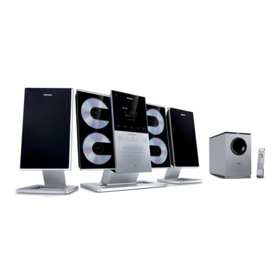
Micro System
©
Copyright 2006 Philips Consumer Electronics B.V. Eindhoven, The Netherlands
All rights reserved. No part of this publication may be reproduced, stored in a retrieval system or
transmitted, in any form or by any means, electronic, mechanical, photocopying, or otherwise without
the prior permission of Philips.
Published by SL 0649 Service Audio
Version 1.0
TABLE OF CONTENTS
Location of PC Boards & Versions Variation ........................ 1-2
Specifi cations ....................................................................... 1-3
Measurement Setup ............................................................. 1-4
Service Aids, Safety Instruction, etc ...........................1-5 to 1-7
Disassembly Instructions & Service positions ......................... 2
Service Test Program .............................................................. 3
Set Block Diagram ................................................................... 4
Set Wiring Diagram ................................................................. 5
Main Board .............................................................................. 6
ECO 6 Tuner Board : Systems Non Cenelec ........................ 7A
Subwoofer AMP Board ............................................................ 8
Display (MCU) Board............................................................... 9
Key Boards ............................................................................ 10
Mechanical Exploded View & Parts List ................................ 11
Printed in The Netherlands
Subject to modification
MCM299
Page
CLASS 1
LASER PRODUCT
© 3141 785 31500
/55
Advertisement
Table of Contents

Related Manuals for Philips MCM299/55


Summary of Contents for Philips MCM299/55
- Page 1 LASER PRODUCT © Copyright 2006 Philips Consumer Electronics B.V. Eindhoven, The Netherlands All rights reserved. No part of this publication may be reproduced, stored in a retrieval system or transmitted, in any form or by any means, electronic, mechanical, photocopying, or otherwise without the prior permission of Philips.
- Page 2 LACATION OF PCBS VERSION VARIATIONS: Type /Versions: MCM299 Features & Board in used: Aux in / CDR in Line Out Video Out Surround Out Subwoofer Out Digital Out Digital in Matrix Surround RDS/NEWS Dolby Pro Logic (DPL) Incredible Surround Karaoke Features Voltage Selector ECO Power Standby (Clock Display Off) ECO6 Tuner Board - Systems Non-Cenelec...
-
Page 3: Specifications
SPECIFICATIONS Specifications and external appearance are subject to change without notice. -
Page 4: Measurement Setup
MEASUREMENT SETUP Use Audio Signal Disc SBC429 4822 397 30184 (replaces test disc 3) L.P.F. = 13 order filter 4822 395 30204 Low pass filter 22kHz S/N and distortion meter e.g. Sound Technology ST1700B LEVEL METER e.g. Sennheiser UPM550 with FF-filter... -
Page 5: Service Aids
SERVICE AIDS ESD Equipment: Service Tools: Anti-static table mat - large 1200x650x1.25mm ...4822 466 10953 Universal Torx driver holder .........4822 395 91019 anti-static table mat - small 600x650x1.25mm ..4822 466 10958 Torx bit T10 150mm ...........4822 395 50456 Anti-static wristband ..........4822 395 10223 Torx driver set T6-T20 .........4822 395 50145 Connectorbox (1M ..........4822 395 11307... -
Page 6: Esd Protection Equipment
WAARSCHUWING WARNING Alle IC’s en vele andere halfgeleiders zijn All ICs and many other semi-conductors are gevoelig voor electrostatische ontladingen (ESD). susceptible to electrostatic discharges (ESD). Onzorgvuldig behandelen tijdens reparatie kan Careless handling during repair can reduce life de levensduur drastisch doen verminderen. drastically. -
Page 8: Service Test Program
SERVICE TEST PROGRAM To hold ALBUM+ & PROGRAM depressed while set on standby Display shows the ROM version V refers to Version "Vy--y MTP xx-xx-2006" y--y refers to Software version number of the uProcessor (Main menu) (counting up from 01 to 99) xx refers to date number of the production. -
Page 9: Set Block Diagram
SET BLOCK DIAGRAM... -
Page 10: Set Wiring Diagram
SET WIRING DIAGRAM... -
Page 11: Main Board
MAIN BOARD TABLE OF CONTENTS Main PCB - Layout Top View ........... 6-2 Main PCB - Layout Bottom View ........6-3 Main PCB - Circuit Diagram (Audio Part) ......6-4 Main PCB - Circuit Diagram (CD Part) ......6-5 Class D Power PCB - Layout Top View ......6-6... -
Page 12: Pcb Layout - Main Board (Top View)
PCB LAYOUT - MAIN BOARD (TOP VIEW) -
Page 13: Pcb Layout - Main Board (Bottom View)
PCB LAYOUT - MAIN BOARD (BOTTOM VIEW) - Page 14 CIRCUIT DIAGRAM - MAIN BOARD AUDIO PART...
- Page 15 CIRCUIT DIAGRAM - MAIN BOARD CD PART...
-
Page 16: Block Diagram
7A-1 7A-1 BLOCK DIAGRAM TUNER BOARD ECO 6 Systems Vcc1 buffer ampl. Stab Stab Discriminator FM-RF FM-IF 1 FM-IF 2 (MPX) Vcc2 1101 Loop (1102) LF filter 10,7 MHz 10,7 MHz 10,7 MHz 1120 left left Stereo right right Decoder Frontend Mixer Det. -
Page 17: Tuner Board Eco6
7A-2 7A-2 1101 A1 1102 B1 1103 F2 1120 E14 1130 A2 TUNER BOARD ECO6 1131 B2 / SYSTEMS NON CENELEC 1132 G13 2101 B3 VERSION PROGRAMMING COMPONENTS 2102 B1 1101 2103 C7 2105 2104 B3 AM-IF1 1130 2105 A2 100n 5111 450kHz... - Page 18 7A-3 7A-3 1101 A6 1120 A4 1132 A5 2128 C4 2138 C2 3142 D2 5110 B3 5114 A2 5123 D5 7112 C1 9104 B5 9107 D4 TUNER ADJUSTMENT TABLE ( ECO6 FM/MW- and FM/MW/LW - versions with AM-frame aerial ) 1102 B6 1130 B5 2106 C5...
- Page 19 SUBWOOFER AMP BOARD TABLE OF CONTENTS PCB - Layout (Top) ............8-2 PCB - Layout (Bottom) ............. 8-2 PCB - Circuit Diagram ............8-4...
- Page 20 PCB LAYOUT - SUB AMP BOARD (TOP VIEW) PCB LAYOUT - SUB LED BOARD...
- Page 21 PCB LAYOUT - SUB AMP BOARD (BOTTOM VIEW)
- Page 22 CIRCUIT DIAGRAM - SUB AMP BOARD +20V 2R328120k 2L980 2.2UH 2R306 100k 2R605 470 1/2W 2SW601 2CN701 2C317 2R701 20V+ +12VA 2C601 2C302 150P 2FB601 1.8K 222P U301A 2R219 NJM4558 2.2UH CN2/20 IC301B 2R302 2R301 2C305 NJM4558 2Q209 2R322 2R323 ZD701 2R307 2Q602...
-
Page 23: Display Board
FTD DISPLAY PIN CONNECTION DISPLAY BOARD TABLE OF CONTENTS FTD Display Pin Connection ........... 9-1 Display PCB - Layout Top View ........9-2 Display PCB - Layout Bottom View ......... 9-3 Display PCB - Circuit Diagram ........9-4... - Page 24 PCB LAYOUT - DISPLAY BOARD (TOP VIEW)
- Page 25 PCB LAYOUT - DISPLAY BOARD (BOTTOM VIEW)
- Page 26 CIRCUIT DIAGRAM - DISPLAY BOARD...
-
Page 27: Key Boards
10-1 10-1 KEY BOARD TABLE OF CONTENTS KEY1 PCB - Layout Top View ........10-2 KEY1 PCB - Circuit Diagram Part ........10-2 KEY2 PCB - Layout Top View ........10-3 KEY2 PCB - Circuit Diagram Part ........10-3... - Page 28 10-2 10-2 PCB LAYOUT - KEY1 BOARD (TOP VIEW) CIRCUIT DIAGRAM - KEY1 BOARD...
- Page 29 10-3 10-3 PCB LAYOUT - KEY2 BOARD CIRCUIT DIAGRAM - KEY2 BOARD...
- Page 30 11-1 11-1 MAIN SET MECHANICAL EXPLODED VIEW...
- Page 31 11-2 11-2 SUBWOOFER MECHANICAL EXPLODED VIEW...
- Page 32 11-3 11-3 MAIN UNIT MECHANICAL & ACCESSORIES PARTS LIST SUBWOOFER MECHANICAL & ACCESSORIES PARTS LIST 9965 000 40380 CONTROL PANEL 9940 000 02823 AM/FM ANT (75R) ASS'Y PACKING 9965 000 42454 TOP COVER 9965 000 42426 FRONT LENS 9940 000 04392 LASER COVER (FOR SANYO CD) 9965 000 42446 TRANSFORMER EI76X40 120/230V...
-
Page 33: Electrical Parts List - Main Board
11-4 ELECTRICAL PARTS LIST - MAIN BOARD C133 9965 000 42428 E.CAP 1000UF 16V -20% Q610 9965 000 38609 TRANSISTORS 2W 8050C C314 9965 000 42429 E.CAP 6800UF 25V -20% Q611 9965 000 38609 TRANSISTORS 2W 8050C C640 9965 000 42428 E.CAP 1000UF 16V -20% Q613 9940 000 04338... -
Page 34: Electrical Parts List - Tuner Board
11-5 ELECTRICAL PARTS LIST - TUNER BOARD 2106 9940 000 00254 TRIMMER 10PF 6MM (WH) 2155 9940 000 00254 TRIMMER 10PF 6MM (WH) 5102 9940 000 01212 AM IFT (BLACK) 7MM 7101 9351 740 80557 IC SM TEA5757H/V1 (PHSE) Y 6130 9940 000 01479 VARICAP DIODE ISV228... - Page 35 11-6 ELECTRICAL PARTS LIST - SUBWOOFER AMP BOARD 2Q602 9965 000 38610 TRANSISTORS 2W 8550C 2Q205 9940 000 04338 TRANSISTORS PMBT3904 2Q203 9940 000 04338 TRANSISTORS PMBT3904 Note: Only these parts mentioned in the list are 2Q207 9940 000 04338 TRANSISTORS PMBT3904 normal service parts.
- Page 36 11-7 ELECTRICAL PARTS - DISPLAY BOARD D402 9940 000 04363 DIODE PMLL4148L D403 9940 000 04363 DIODE PMLL4148L D404 9940 000 04363 DIODE PMLL4148L D405 9940 000 04363 DIODE PMLL4148L D409 9965 000 42437 DIODE SS14 SMA/DO-214AC IC401 9965 000 42440 MCU GY372U -USA (OTP) IC402 9940 000 02839...
- Page 37 11-8 ELECTRICAL PARTS LIST - KEY BOARD LED421 9940 000 01482 LED LAMP 3MM (RED) LED501 9965 000 42443 LED LAMP 2X5X7MM(S.BLUE) LED502 9965 000 42443 LED LAMP 2X5X7MM(S.BLUE) LED503 9965 000 42443 LED LAMP 2X5X7MM(S.BLUE) LED504 9965 000 42443 LED LAMP 2X5X7MM(S.BLUE) LED505 9965 000 42443 LED LAMP 2X5X7MM(S.BLUE)
Need help?
Do you have a question about the MCM299/55 and is the answer not in the manual?
Questions and answers