
Summary of Contents for Essence Security EverGuard ES7000EG
-
Page 1: Control Panel
EverGuard Control Panel User Guide ES7000EG Version 1.7_01 December 2011 Essence Group Part of the... - Page 2 © 2011 Essence Security International Ltd. All rights reserved. This document is the protected intellectual property of the Essence Security International Ltd. Any copying, reprinting, reuse, reproduction adaptation distribution or translation without the prior written permission of Essence Security Ltd is prohibited.
-
Page 3: Table Of Contents
Table of Contents Table of Contents Overview ..................... 5 Installation ..................6 ES7000EG Wall Mount................. 6 GSM/GPRS Modem Installation ..............11 2.2.1 GSM/GPRS Modem Components ............. 11 2.2.1.1 GSM/GPRS Modem ............11 2.2.1.2 Antenna and Coaxial Cable..........12 2.2.1.3 GSM/GPRS Modem Connector .......... 12 2.2.2 Mounting the GSM/GPRS Modem Antenna........ - Page 4 Table of Contents 3.3.2.1 Toolbar ................46 3.3.2.2 Status Bar ..............47 3.3.2.3 Navigation Pane ............. 47 3.3.2.4 Main Tab ............... 47 3.3.2.5 CMD Tab ................ 48 3.3.2.6 Status Tab ..............49 3.3.2.7 The control panel is divided into several parameter sets: ..50 Maintenance ..................
-
Page 5: Overview
Overview 1 Overview The ES7000EG is a two-way, wireless control panel unit comprising the main element of the EverGuard Control Panel security system. This unit receives Radio Frequency (RF) signals from a full array of sensors and detectors, remote access devices and interface devices, such as a key fob and key pad. -
Page 6: Installation
Installation 2 Installation 2.1 ES7000EG Wall Mount The ES7000EG can be mounted on a wall using the wall mount provided. In addition, you must verify that there is adequate reception from the key pad (ES700KPD) to the ES7000EG control panel and vice versa. Note: The distance between the ES7000EG control panel and the peripheral devices can be a maximum of 700 meters (2296 feet) (Open Air Nominal) if there are no obstacles. - Page 7 Installation In order to use the DVK RF test tool, the control panel location should be selected first. The installer can then use the DVK tool to select the location for all other devices. To mount the ES7000EG control panel: Identify a suitable location for the ES7000EG control panel according to the guidelines above.
- Page 8 Installation Attach the ES7000EG control panel to the wall mount, top first, then bottom as shown in the figures below. ES7000EG control panel snaps into the provided clips. Using the appropriate screwdriver, insert the tamper screw and secure it in place as shown in the figure below.
- Page 9 Installation WARNING! 220V Hazard! Make sure AC cable is disconnected before applying the following sections 10. Measure distance end-to-end of power cable from the ES7000EG control panel to the power source to ascertain that it is of sufficient length. 11. Insert the power cable through the punch-out opening and secure the wires to the terminal block connectors as shown in the figure below.
- Page 10 Installation GSM/GPRS Modem Installation instructions in section 2 .2 below 13. Attach the top cover, top first, then, bottom as shown in the figure below. 14. Connect the other end of the power cable to a plug. 15. Insert the plug into the designated power socket. The wall mount and installation are complete.
-
Page 11: Gsm/Gprs Modem Installation
Installation 2.2 GSM/GPRS Modem Installation The GSM/GPRS modem and antenna must be installed inside the ES7000EG control panel for wireless communication. The mounting screws are supplied with the modem kit. Note: Be sure to follow the installation instructions closely so that the antenna does not get disconnected. -
Page 12: Antenna And Coaxial Cable
Installation Antenna Connector Board-to-Board Connector (back view only) 2.2.1.2 Antenna and Coaxial Cable The figure below displays the Antenna and Coaxial Cable. The GSM/GPRS Antenna is comprised of: Antenna COAXIAL Cable Antenna Connector (at the end of the COAXIAL Cable) 2.2.1.3 GSM/GPRS Modem Connector The GSM/GPRS Modem Connector is inside the ES7000EG control panel, on the... - Page 13 Installation Note: The pictures of the GSM/GPRS module below are an example only. The actual brand and part-number of the module may vary. 2. Verify that the connection is stable and firm. 3. With the ES7000EG control panel open, locate the GSM/GPRS Modem Connector at the corner of the panel’s circuit board.
- Page 14 Installation 4. Place the GSM/GPRS modem so that the screw holes line up with the screw holes protrusions. Note: Be careful not to not to disconnect the antenna while performing this function. Antenna disconnection causes a fault in the system when trying to connect to the GSM network.
-
Page 15: Mounting The Gsm/Gprs Modem Antenna
Installation 2.2.2 Mounting the GSM/GPRS Modem Antenna The GSM/GPRS modem antenna is mounted on the upper side of the ES7000EG control panel’s inner casing. Note: Be sure to follow the installation instructions closely so that the coaxial cable is positioned correctly and the antenna does not get disconnected. - Page 16 Installation Insert the SIM Card according to the instructions in section 2 .3 “ Inserting the SIM Card”. The figure below displays the full GSM/GPRS hardware assembly. Note: When using a Samsung brand module with the ES7000EG control panel connected to a power source, The LED lights up to indicate that the GSM/GPRS Modem is synchronized with the GSM network.
-
Page 17: Inserting The Sim Card
Installation 2.3 Inserting the SIM Card As part of the GSM/GPRS transmission configuration, a SIM card is inserted into a holder on the ES7000EG control panel’s circuit board. To insert the SIM card: Gently press down with your finger to slide the cover and pull the flap in the direction as shown below. -
Page 18: Connecting The Mini Usb Cable
Installation Connecting the Mini USB Cable For initial setup using the Atlas Mobile application with the BlackBerry Smartphone, each professional installer is provided with a Wireless Bluetooth dongle and a specially designed Mini-USB cable that can be attached to the ES7000EG control panel for setup. - Page 19 sound the “long dropping tone” which symbolizes the “plug-out indication”. EverGuard Control Panel...
-
Page 20: Operation
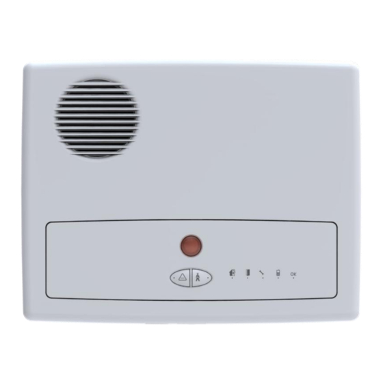
Operation 3 Operation 3.1 About the ES7000EG Control Panel Equipment The ES7000EG Control Panel can utilize the following auxiliary equipment: GSM/GPRS Modem – required for wireless communication Antenna and Coaxial Cable – required for wireless communication 3.1.1 ES7000EG Hardware Front and Back Views The figures below display the front and back of the ES7000EG control panel. - Page 21 Operation Table 1: ES7000EG Control Panel Front View and LED States Item Speaker S.O.S Button and LED Call guard Button and LED Arm LED Open zone LED System Fault LED Communication LED Power LED Call Monitor Station and LED Figure 2: ES7000EG Control Panel Side View Table 2: ES7000EG Control Panel Side View Item Power Cable Punch-out...
- Page 22 Operation Figure 3: mini-USB with rubber cap EverGuard Control Panel...
-
Page 23: Buttons And Indications
Operation 3.2 Buttons and Indications 3.2.1 ES7000EG Hardware Front and Back Views The figure below displays the front and back of the ES7000EG control panel. Table 3: ES7000EG Control Panel Front View and LED States LED Status Item Flashes Speaker S.O.S Button and LED Red Flashing Call guard Button and LED... -
Page 24: Audible Indicators
Operation Note: The LED flash rate is 0.5 seconds per interval Table 4: ES7000EG Control Panel Side View Item Power Cable Punch-out Punch-out Open/Close Clip SD Card Slot Mini USB serial connector 3.2.2 Audible Indicators The audible indicators of the ES7000EG control panel are detailed in the table below. -
Page 25: Power Status
Operation Action Tone Pattern description Tone Pattern Two long, high octave beeps Chime separated by a delay A continuous siren in a rising and Alarm (Security) falling cycle A continuous siren in a rising and Alarm (Safety) falling cycle 3.2.3 Power Status A single LED provides the power status information. -
Page 26: System Status
Operation 3.2.5 System Status A single status LED provides the system status information. The table below details the system status indicators of the ES7000EG control unit. Table 8: System Status Indicators Crucial Fault Crucial faults Fault Faults The Flashing No System Fault No system fault 3.2.6 Arm Status... -
Page 27: Open Zone Status
Operation 3.2.7 Open Zone Status A single status LED provides the Open Zone status information. The table below details the Open Zone status indicators of the ES7000EG control unit. Table 10: Open Zone Status Indicators Open Zone While there is an open Yellow zone Detection... -
Page 28: Function
Operation 3.2.9 S.O.S function In case of emergency, the user should press on the S.O.S button and then the system will notify the central monitoring station. When the LED stays permanently red it means that the S.O.S signal has been received correctly. -
Page 29: Detailed Operation And Modes
Operation 3.2.11 Detailed Operation and Modes 3.2.11.1 The Arm Cycle The diagram below illustrates the phases of the Arm cycle. EverGuard Control Panel... -
Page 30: Maintenance
Operation 3.2.12 Maintenance A singe Maintenance LED provides the system status when the ES7000EG control panel is set to Maintenance mode. When the communications mini USB connecter is attached or detached, an audible beep is sounded. Table 14: Maintenance Related Indicators Attach Indication/ Attach After attachment,... -
Page 31: Alarm
Operation 3.2.14 Alarm A single LED indicates the Alarm status activated when an alarm is triggered. An audible alarm is sounded. Table 16: Alarm Status Indicators Alarm in Process Alarm While alarm is in Red Flashing - S.O.S progress, its duration could be configured Red Flashing - call guard... -
Page 32: Optional Settings And Defaults
Operation 3.3 Optional Settings and Defaults You can configure basic parameters for the EverGuard Control Panel using the Atlas Mobile application and the ESI-CMS applications. 3.3.1 Atlas Mobile Application To configure the Control Panel’s automated behavior: On the Installation screen, roll the trackball to the Control Panel icon. - Page 33 Operation Configuring System and Video Scenarios When configuring the Security system you must set: Full entry, part entry and exit parameters. These parameters set the number of seconds Between entry and keying in the entry pin code. Between keying in the pin code and exiting before the alarm sounds.
- Page 34 Operation Figure 5: ES7000EG System Configuration Menu Note: The CPU A and CPU C are Read-Only parameters. For Full and Part, Entry and Exit, roll to the desired parameter. The list of time duration options appears. The range is 1 to 180 seconds. Note that for compliance with the EN 50131 standard, both Entry and Exit times must be set to values of 45 seconds maximum.
- Page 35 Operation Click Save. A progress screen appears. When processing is complete a message appears stating that the record was updated successfully. Click OK. The Editing Video Scenario Screen reappears. Click Back to return to the System Configuration Screen. Click Back to return to the Installation Screen. ...
- Page 36 Operation Select the desired provider and click. The selected provider is listed on the screen and a predefined dialing sequence is added. A selection of at least one communication channel is mandatory. A pop up message will appear in case of no communication channel is chosen. Roll to Delay and choose yes or no.
- Page 37 Operation Table 17: Operation codes Status Description Trigger Set up Preset Testing End Installation Operating Panel activation by: Monitoring station operation (command) ESI-CMS ® Blackberry The operation codes are set on the control panel depending on the trigger. On the Installation screen roll the trackball to the Operation Code icon.
- Page 38 Operation Figure 10: Atlas Mobile Panel Status Roll to Code and Click. Enter the 4 digit activation code. Click Update. A message appears stating whether or not the activation code was accepted and stating the current status of the system. Click OK.
- Page 39 Operation Click. The Account Settings screen appears. This screen appears automatically only for new control panels that have not yet been assigned an account number. Figure 12: ES7000EG Account Settings Note: In order to check the account number and GSM phone number for configured control panels, click the account info button to access this screen manually.
- Page 40 Operation Table 18: User types Type Attendance Temporary Master Not available Standard Access Only Attendance – keeps track of access (entrances and exits) in a log on the panel that is sent to the control center. This log can be accessed at a later date. Temporary –...
- Page 41 Operation Figure 14: Installation - Users Roll to New and click. The Editing User screen appears. Figure 15: Editing User Roll to Name and type in the name of the user. Roll to Type and click. The list of Type options appears: ...
-
Page 42: Esi-Cms Application
Operation When processing is complete a message appears stating that the record updated successfully. Click OK. The Installation – User Screen reappears with the new user highlighted. Click Back to return to the Installation Screen. To Edit a User: On the Installation screen, roll the trackball to the User Settings icon. - Page 43 Operation Figure 16: Connect Screen Leave the Username and Password fields empty. Under Protocol, select the radio button for: Upload -to make either a direct and remote connection to the ES7000EG control panel in order to change configuration Remote boot - to make a remote connection to a deployed ES7000EG control in order to update firmware Open the Connect Link dropdown menu, which opens a list of available ports for different communication channels.
- Page 44 Operation To download the new configurations to the ES7000EG Control Panel: From the Remote Panel menu, select Download or Click from the toolbar. The changed configurations are downloaded to the control panels. To disconnect from an ES7000EG control panel: From the Link menu select Disconnect or Click on the toolbar.
- Page 45 Operation Partition – In Part Arm mode, indicates the number of the partition that is armed Communication Status – Communication mode in operation NTS - no transmission status CCS - continuous cycle status (default setting and after activation) ...
-
Page 46: Toolbar
Operation Upload – uploads the configuration from the ES7000EG or ES7000EG Control Panel to the ESI-CMS To exit the Panel Info dialog box, click . You are returned to the main screen. EverGuard Control Panel Main Interface ESI-CMS main interface contains the following elements: ... -
Page 47: Status Bar
Operation Disconnect RF Input Monitor RF Output Monitor Connect Download The use of these buttons is detailed in the relevant procedures throughout this document. 3.3.2.2 Status Bar The Status bar displays the current connection status of the panel, Connected/Disconnected, as well as the Communication Status: ... -
Page 48: Cmd Tab
Operation Note: by default, every screen that is displayed from the navigation pane contains parameters that cannot be modified until they are enabled. 3.3.2.5 CMD Tab The CMD tab controls many of the security commands in this single navigation pane. It is divided into the following sections: ... -
Page 49: Status Tab
Operation After any change, press the communication button, and a dialog box appears to state that the Communication status is being changed. 6. Under Home Automation, to activate a door lock, click Door Lock. To activate an RF Output device, click RF Output. To activate and X-10 device, click X-10. -
Page 50: The Control Panel Is Divided Into Several Parameter Sets
Operation Figure 19: System Screen To configure the Control Panel 3.3.2.7 The control panel is divided into several parameter sets: Timer Delay – the delay of the alarm when entering/exiting Sound – the alarm volume and setup Power –... - Page 51 Operation Figure 20: Control Panel Screen 2. To edit a specific parameter, mark the relevant checkbox. The parameter is then enabled and you can modify it. Under Timer Delay, parameters enable you to set the, configure the entry/exit timed devices using the following Timer Delay parameters: ...
- Page 52 Operation Under Power, set the indicators that notify the monitoring station of power failure for the following parameters: Random time for 220v fail indication – Enables or disables the random time message that is sent to the monitoring station. This sends a message at random time intervals to the monitoring station along with the fixed time message.
- Page 53 Operation Note: If the panel connection has been set to Serial (COM), the GSM module must be disabled. SIM Pin-Code - Enables or disables the SIM pin code. When using SIM cards that are unlocked and do not require a PIN code, the SIM Pin-Code parameter should be disabled.
- Page 54 Operation Figure 21: Dialer Configuration Dialog To edit a specific parameter, mark the relevant checkbox. The parameter is enabled. You can then modify it. For SMS Configuration, GPRS Configuration and GSM DATA Configuration set the following parameters: ACK Timeout –Defines the maximum amount of time (in seconds) that the system waits to receive an acknowledge message before continuing to the next dialing option.
- Page 55 Operation To configure the APN (GPRS) Configuration: Using the GPRS Configuration dialog box, configure the destination servers for indoor/outdoor videos. The APN (GPRS) Configuration screen is divided into the following parameters sets: Test Scenario Configuration – used during system testing and when modifying the configuration ...
- Page 56 Operation Password – enter the Password received from the local SIM card provider APN – enter the Access Point Name received from the local SIM card provider User Name – enter the User Name received from the local SIM card provider Click Close.
- Page 57 Operation Figure 23: Video Configuration Suspect Tab To access a specific tab page, click on the appropriate tab. For all tabs (except for the Configuration tab), set the following parameters: To enable, check the checkbox to activate all parameters underneath. ...
- Page 58 Operation Figure 24: Video Scenario Configuration Screen Tamper Alarm Tab ID of first IVD associated with scenario ID of second IVD associated with scenario Set each to a designated ID device between 1 and 64 that corresponds to the appropriate IVD devices in the control panel.
- Page 59 Operation 128k 256k OTA Enable – check to enable object tracking OTA Crop Enable – check to enable zoom in upon movement detection Note: OTA Enable and OTA Crop Enable can only be enabled with a resolution set to 320x240.
- Page 60 Operation Device – select a device or a protocol from the dropdown list. The list groups peripherals that use the X10 and RF Output protocols. These protocols are set in the relevant Main tab category. Door Lock is an independent action not grouped by protocol.
- Page 61 Operation To configure the Dialer: Using the Dialer Screen, set the dialing ID options On the MAIN tab, click Dialer. The Dialer screen appears. Figure 28: Dialer Screen Under Phone Number, select a line item or from the Phone ID dropdown list, select one of the thirteen dialing IDs or three video IDs to change the information.
- Page 62 Operation and specify the number of redial times (specifically with messages, voice, and video). Select the Message, Voice, or Video tab to set the configurations. For Sequence, enter up to six numbers to be called. From the No. of Retries dropdown list, select between 1 and 8 times to redial the sequence.
- Page 63 Operation Figure 30: User Settings Screen Under Users, select a line item or from the User ID dropdown list, select the user ID (the range is between 1 and 32). For Name, enter a user name (up to 12 characters) (optional). For Password, enter a password (up to 8 characters).
- Page 64 Operation For Temporary, from the No. of Accesses dropdown list, assign the maximum number of times the user may access the premises. The range is 1 to 255. Click Update. The User data is refreshed and displayed accordingly. To configure the Customer Labels parameters: The technician installing the system can define selected areas to be armed designating these areas as zones.
- Page 65 Operation To edit a Custom Label: Select the Label ID on the main screen. Edit the free text in the label field. Click Update. To delete a Custom Label: Select the Label ID on the main screen. Delete the label text. Click Update.
-
Page 66: Maintenance
Maintenance 4 Maintenance A singe Maintenance LED indicates the system status when the ES7000EG control panel is set to Maintenance mode. When the communications mini USB connecter is attached or detached, an audible beep is sounded. Table 19: Maintenance Related Indicators Attach Indication/ Attach After attachment,... -
Page 67: Fcc Radio Frequency Interference Statement
Consult the dealer or an experienced radio/TV technician for help. Essence Security is not responsible for any radio or communication interference caused by using other than specified or recommended cables and battery or by unauthorized changes or modifications to this equipment. -
Page 68: Specifications
Specifications 6 Specifications Electrical Power Supply: Advanced switching power supply. Input: 100~240 VAC, 50/60 Hz internal AC to DC adaptor. Lithium Polymer rechargeable backup battery Battery Life: Provides at least 60 hours backup power during temporary loss of power source Backup battery spec: Lithium Polymer battery Rated average voltage: 3.7V... - Page 69 Specifications Communication Cellular network: GSM/GPRS Module Modules: Quad band (850/900/1800/1900 MHz) Transmission time: The time measured from transmission by a wireless detector to the time the system is requesting connection from the cellular network. SMS: 0.2 ±0.05 Sec GPRS: 1 ±0.3 Sec GSM data: 5.5 ±...
- Page 70 Specifications Storage Temperatures: -20°~60° Celsius (-4° - 140° Fahrenheit) Humidity: 85% relative humidity, non-condensing Physical Dimensions: (L x W x D) 250mm x 185mm x 50mm (9.84” x 7.28” x 1.97”) Weight: 1180 grams (incl. battery) – unit only Color: Glossy White Mounting: Wall, with bracket...
- Page 71 Specifications Markings: EverGuard Control Panel...
Need help?
Do you have a question about the EverGuard ES7000EG and is the answer not in the manual?
Questions and answers