Advertisement
Quick Links
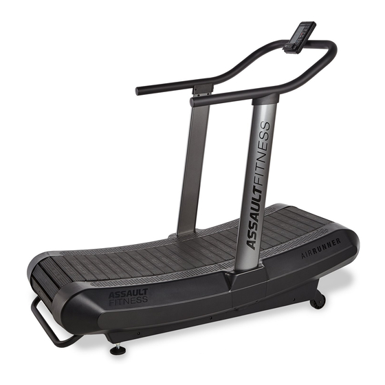
AS SHIPPED
Speed Sensor Cable - Upper (559a)
Console Cable
Handrail (504)
(514a)
Console (514)
Console Cover
Console Cover
- Left Inner (529)
- Right Outer (531)
Console Cover
Console Cover
- Left Outer
(528)
- Right Inner (530)
Speed Sensor
Cable - Upper (559b)
Sidecase Center Cover
- Right (510)
Speed Sensor
Cable - Lower (560a)
Sidecase Center Cover
- Left (507)
Main Assembly (A)
ASSEMBLY
Introduction
• The Assault Fitness AirRunner treadmill requires only minor assembly. All tools required to complete the initial
setup and assembly have been included in the Assembly Hardware Kit.
• Remove the unit and all parts from the carton and packaging. Confirm all parts shown in the section titles As
Shipped are included before attempting assembly of the AirRunner.
Assembly Step One: Upright Installation
• Locate the Speed Sensor Cable – Lower (549a) and ensure the end/connector is extending from the main
frame.
• Raise the Upright – Left vertically, ensuring the Keyholes are located at the bottom. Align the Upright - Left
keyholes with the two posts located on the main frame. This will support the upright while completing the
installation.
• Connect the Speed Sensor – Lower (549a) and Speed Sensor Cable – Middle (560b) connectors firmly.
• Locate three (3) sets of #534 Hex Screws and #562 Flat Washers, and loosely thread each assembly through the
Left Upright and into the main frame. Tighten the screws firmly.
• Hang the Upright – Right keyholes onto the Main Frame posts and install the remaining three (3) sets of #534
Hex Screws and #562 Flat Washers.
560(a)
Upright - Left
562
534
549a
560b
For more information or questions regarding your equipment, please visit our website at
QUICK START
GUIDE
MANUAL TREADMILL
Part #23-AS-566 US-English v1.0 05-Mar-17
ASSEMBLY TOOLS
Upright - Left
Speed Sensor
(502)
Cable
- Middle (560a)
13/16mm
5mm
Open-Ended
Hex Wrench
Wrench
Speed Sensor
Cable - Middle
(560b)
Upright
HARDWARE DESCRIPTION
- Right (503)
Hex Screw M10 x 75mm (534)
Phillips Head Screw M4.2 x 13mm (538)
Button Head Hex Screw M8 x 20mm (535)
Flat Washer Ø20OD x 11ID x 1.5t (562)
Keyholes
Posts
5803 Newton Drive Carlsbad, California 92008 Ph. 1.888.815.5559
AssaultFitnessProducts.com
Assembly Step Two: Sidecase Covers
• Locate the Sidecase Center Cover - Left (507). Align the tabs locate at the top with the receivers on the installed
sidecase plastics. To install, the cover will hinge downward and snap in place. Ensure the outer surface of the cover
is flush or aligned with the adjacent plastics.
• Secure with two (2) #537 Phillips Head Screws.
Assembly Step Three – Handrail & Console Installation
• Remove the four (4) #564 Hex Screws
4mm
AA Alkaine
from the backside of the Console (514)
Hex Wrench
Batteries
4 pieces
and set them aside.
• Connect the Console Cable (514a) and
Speed Sensor Cable – Upper (559b)
connectors and carefully tuck the excess
cable into the Handrail.
• Loosely thread the four (4) #564 Hex
Screws through the mounting plate on
the Handrail and into the backside of the
Console (514). When all four (4) screws
are installed, tighten firmly.
• With the help of a second person, support
the Handrail assembly above the uprights
DRAWING QUANTITY
and connect the Speed Sensor Cable –
Upper (559b) and Speed Sensor Cable –
6
Middle (560a) connectors. Carefully tuck
the connectors and excess cables into the
12
left Upright.
6
• Set the left and right Handrail brackets
6
inside the left and right Uprights. While
supporting the Handrail Assembly,
loosely thread three (3) #535 Button
Head Hex Screws through the left
Upright and into the Handrail bracket.
Repeat this step for the right side and tighten all six (6) screws firmly.
• Align the Console Cover – Left Outer (528) with the outside of left Handrail bracket, and thread two (2) #537
Phillips Head Screws through the handrail bracket and into the #528 Cover. Repeat this step for the right side
with Console Cover – Right Outer (531).
• Align the Console Cover – Left Inner (529) with the inside of the left Handrail bracket install two (2) #537
Phillips Head Screws through the #529 Cover and into the #528 Cover.
• Align the Console Cover – Right Inner (530) with the inside of the right Handrail bracket and install two (2)
#537 Phillips Head Screws through the #530 Cover and into the #531 Cover.
Assembly Step Four – Final Adjustments
• Identify a suitable location that is level and offers enough space for the unit with the minimum required free
space. It is recommended that the AirRunner be sited with a minimum of 0.5 meters (19.7 in.) of clearance from
the nearest walls or other equipment to the left, right and front of the unit. A minimum of 2.0m (79") of clearance
should be maintained to the rear of the AirRunner.
• To relocate, raise the rear of the unit with by grasping the transport handle and slowly rolling the AirRunner to
the desired location.
• Ensure the unit is level and does not rock by adjusting the Stabilizer Leveling Feet. Two feet are located at the rear
Upright - Right
of the main frame. As a starting point, loosen each foot by threading the assembly downward/clockwise, and
then thread the locknuts downward (clockwise) against the base of the foot. Check the unit for stability and make
any adjustments as necessary. Once stable, lock the Stabilizer Leveling Feet in place by tightening the jamb nut
upward/counter-clockwise, against the underside of the frame to lock the current positions for each foot.
• Congratulations. The assembly of your Assault Fitness AirRunner treadmill is complete. Please read all included
information, user guides and warnings before use.
562 534
Stabilizer
Leveling
Foot
© Assault Fitness 2017
Upright
507
537
537
504 559b
528
535
Upright
CAUTION:
THIS TREADMILL IS HEAVY. INJURY CAN OCCUR IF PROPER LIFTING TECHNIQUES
ARE NOT PRACTICED.
510
537
537
514a
514
Handrail (504)
531
564
529
537
530
537
535
559b
535
560a
535
535
535
Advertisement

Summary of Contents for Assault Fitness Products Air Runner 23-AS-566
-
Page 1: Quick Start
QUICK START Assembly Step Two: Sidecase Covers • Locate the Sidecase Center Cover - Left (507). Align the tabs locate at the top with the receivers on the installed sidecase plastics. To install, the cover will hinge downward and snap in place. Ensure the outer surface of the cover GUIDE is flush or aligned with the adjacent plastics. -
Page 2: Quick Start Guide
QUICK START GUIDE will then post. Adjust the displayed time value with the UP or DOWN key and press ENTER to confirm. The default rest interval will post. Adjust the value and confirm by pressing ENTER. MANUAL TREADMILL Run: The console will display the current Work/Rest interval and the timer display will count down for each CONSOLE FEATURES interval.
Need help?
Do you have a question about the Air Runner 23-AS-566 and is the answer not in the manual?
Questions and answers