Table of Contents
Advertisement
Quick Links
Thermostat Owners Manual
Model:TOUCH ME 1
Congratulations!
Your new thermostat will provide years of reliable service. By saving energy, your
thermostat will pay for itself during its first season of use. Thanks you for buying our
product!
Please read this manual for complete instructions on installing and operating your
thermostat. If you require further assistance, please feel free to contact us
IMPORTANT INFORMATION
1. This thermostat will NOT control 110/220V baseboard electric heating systems.
2. Temperature Range
This thermostat can be programmed between 41˚F and 95˚F (5˚C and 35˚C) in HEAT
mode, 45˚F and 99˚F (7˚C and 37˚C) in COOL mode. However, it will display room
temperatures from 32˚F to 99˚F (0˚C and 37˚C). "HI" will be displayed if the temperature
is higher than 99˚F (37˚C), and "LO" will be displayed if the temperature is lower than
32˚F (0˚C).
This thermostat will automatically cutoff in Heat mode if the temperature rises above
95˚F (35˚C), and automatically cutoff in Cool mode if the temperature drops below 45˚F
(7˚C).
3. Compressor Protection
This thermostat provides a 4 minutes delay after shutting off the cooling system before it
can be restarted. This feature will prevent damage to your compressor caused by rapid
cycling. It does not prevent a rapid compressor restart due to short power outages.
4. Battery Warning
Two fresh AAA alkaline batteries should provide well over one year of service. However,
when the batteries become drained, the Low Battery Indicator will flash on the display.
When this message occurs, install new alkaline batteries. Once the batteries have
become too low to ensure proper operation, your system will be turned off, and the
display will be cleared except for flashing Low Battery Indicator on the LCD display.
CAUTION: When only the Low Battery icon flashes on the display, the
thermostat is shut down, and your system will no longer operate.
In this condition, there is no temperature control of your
dwelling.
NOTE: The backlight will not function when the thermostat is in low battery condition.
NOTE: If you plan to be away from the premises over 30 days, we recommend that you
replace the old battery with new alkaline battery prior to leaving.
5.Power supply
The thermostat shall be powered by 24 VAC and with battery as backup.
FEATURES
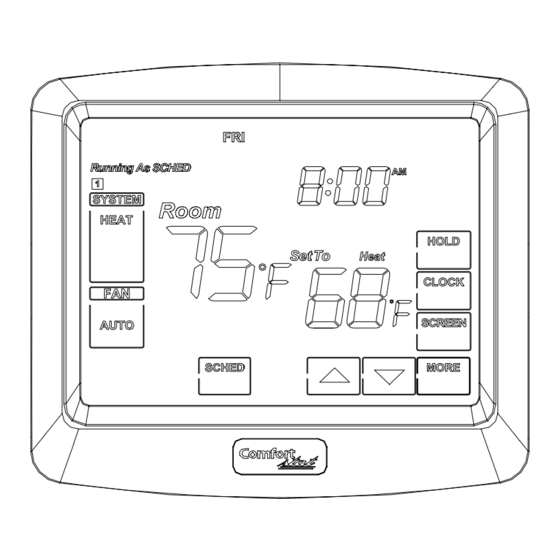
Structure of thermostat and explanation for the LCD and keypad.
indicates the current
days of the week
system temperature
Programming times
The COOL, HEAT OFF
AUTO OR EMER will
display when the COOL,
HEAT OFF AUTO OR
EMER is on
the AUTO , ON will display
when the AUTO, ON is on
enter into the system
menu and modify the
program days
enter into the scheduling mode
lowers temperature setting
save the current setting and quit the display mode
raises temperature setting
We are pleased you have selected one of our broad lines of wall thermostat. Our
products are manufactured to high quality standards and are designed for years of
service.
Read This Before Installing Thermostat
OPERATION
YOUR THERMOSTAT REPLACES
Description
Heat Pump (No Aux. or Emergency Heat)
Heat Pump (with Aux. or Emergency Heat)
Standard Heat & Cool Systems
Two Stage Heat & Two Stage Cool
Standard Heat Only Systems
Millivolt Heat Only Systems– Floor or Wall
Furnaces
Standard Central Air Conditioning
Gas or Oil Heat
Electric Furnace
Hydronic (Hot Water) Zone Heat-2 Wires
Hydronic (Hot Water) Zone Heat–3 Wires
NOTE: This Thermostat will NOT control 110/220Volt systems.
IMPORTANT
Read the entire installation section of this Owner's Manual thoroughly before you begin
to install or operate your Thermostat.
This thermostat can be used for conventional or heat pump systems,
please configure the thermostat according to Configuration Menu
before operation.
INSTALLATION
What You Need
This thermostat includes two #8 slotted screws and four wall anchors for mounting. To
install your controller, you should have the following tools and materials.
■ Slotted Screwdriver(s)
■ Small Philips screwdriver
■ Electric drill and 3/16" bit
■ Two 1.5V (AAA) size alkaline battery (included)
CAUTION:
To prevent electrical shock and/or equipment damage, disconnect electric power
to system at main fuse or circuit breaker box until installation is complete.
Before removing wires from old thermostat's switching subbase, label each wire with the
terminal designation it was removed from.
1. Shut off electricity at the main fuse box until installation is complete. Ensure that
electrical power is disconnected.
2. Remove Old Thermostat: A standard heat/cool thermostat consists of three basic
parts:
a. The cover, which may be either a snap-on or hinge type.
b. The base, which is removed by loosening all captive screws.
c. The switching subbase, which is removed by unscrewing the mounting screws that
hold it on the wall or adaptor plate.
3. Remove the front cover of the old thermostat. With wires still attached, remove wall
plate from the wall. If the old thermostat has a wall mounting plate, remove the
thermostat and the wall mounting plate as an assembly.
4. Identify each wire attached to the old thermostat.
5. Disconnect the wires from the old thermostat one at a time. DO NOT LET WIRES
FALL BACK INTO THE WALL.
6. Install new thermostat using the following procedures.
WARNING
Does not use on circuits exceeding specified voltage. Higher voltage will damage
control and could cause shock or fire hazard. Do not short out terminals on gas
valve or primary control to test. Short or incorrect wiring will damage thermostat
and could cause personal injury and/or property damage.
Attach Thermostat Base to Wall
1. Remove the packing material from the thermostat. Gently pull the cover straight off the
base. Forcing or prying on the thermostat will cause damage to the unit.
2. Connect wires beneath terminal screws on base using appropriate wiring schematic
(see fig 4 through 6 and fig 1 ).
3. Place base over hole in wall and mark mounting hole locations on wall using base as
a template.
4. Move base out of the way. Drill mounting holes.
5. Fasten base loosely to wall, as shown in figs2 and figs3 . using four mounting screws.
6. Push excess wire into wall and plug hole with a fireresistant material (such as
fiberglass insulation) to prevent drafts from affecting thermostat operation.
Figure 1. Wiring Diagrams
Wiring Diagrams
T1
T2
Reversing
Valve
Energized in
Cool Mode
Remote
Sensor
Figure 4.Typical wiring diagram for single transformer heat pump systems
T2
T1
Reversing
Valve
Energized in
Cool Mode
display current time of day, hold
Remote
time remaining or number of
Sensor
vacation days remaining
Figure 5. Typical wiring diagram for two transformer heat pump systems with NO safety circuits
show the current
setting temperature
sets a permanent hold and
activates vacation hold
T1
T2
sets the time
Reversing
2nd Stage
Reversing
forward or back
Valve
Compressor
Valve
locks out the screen
Energized in
Energized in
Cool Mode
to allow for cleaning
Heat,
Emergency
review total filter usage
Remote
Mode
Sensor
Figure 6. Typical wiring diagram for two transformer heat pump systems with safety circuits in
BOTH systems
Install AAA batteries
• The thermostat requires 2 AAA batteries to operate .
• Install 2 AAA alkaline batteries according to the polarity noted in the compartment. LCD
segments will go on.
NOTE: Replace the batteries when this LOW battery indicator appears on the display or
once a year.
Yes
Yes
Yes
Yes
Yes
Yes
Yes
Yes
Yes
Yes
No
Heat Pump Terminal Outputs
Refer to equipment manufacturers' instructions for specific system wiring information.
You can configure the thermostat for use with the following heat pump system types:
Single stage compressor system; multiple stage compressor system; gas or electric
backup. This thermostat is designed to operate a single-transformer system. If you have
a two-transformer system, cut and tape off one transformer. If transformer safety circuits
are in only one of the systems, remove the transformer of the system with NO safety
circuits. If required, replace remaining transformer with a 75VA Class II transformer. After
disconnecting one transformer, the two commons must be connected together.
Use the terminal output information below to help you wire the thermostat properly for
your heat pump system. After wiring, see CONFIGURATION section for proper
■ Hammer
thermostat configuration.
SYSTEM
C*
R
E/W1
W2
Y1
Y2
G
O
B
L
System mode operation
The System mode of the thermostat determines the Operating mode of the thermostat.
You may select COOL, OFF, HEAT, AUTO,EMER. In order to take full advantage of this
thermostat's feature, we recommend using the AUTO mode. Refer to the Auto Season
Changeover information on Auto Season Changeover.
NOTE: Anytime you install or remove the thermostat form the wallplate,
Figure 2.Mounting Wallplate
Figure 3. Mount thermostat to wallplate
2nd Stage
Reversing
SYSTEM
Compressor
Fan
Emergency
Valve
MONITOR
Relay
Heat
Energized in
SWITCH
TRANSFORMER
Aux
Relay
Heat,
Compressor
(Class II Current Limited)
Heat
Emergency
Contactor
Relay
Mode
24 VAC
2nd Stage
Reversing
Limit or Safety
Compressor
Fan
Emergency
Valve
SYSTEM
Switches
Relay
Heat
Energized in
MONITOR
Aux
Relay
Heat,
SWITCH
Compressor
Heat
Emergency
Contactor
Relay
Mode
24 VAC
Limit or
SYSTEM
Fan
Emergency
Safety
MONITOR
24VAC
120VAC
Switches
Relay
Heat
SWITCH
Aux
Relay
Compressor
24VAC
Heat
Auxiliary Heating
Contactor
The accessory relay scheme
Accessory
Relay
Transformer
is required when safety
Relay N.O.
(Class II Current
COMMON
circuits ezist in both systems
Contacy
Limited)
Limit or
Safety
TWO COMMONS MUST
Switches
BE JUMPERED TOGETHER!
COMMON
24 VAC
120 VAC
f
THERMOSTAT TERMINALS (HEAT PUMP)
Heat Pump 1
Heat Pump 2
24 Volt(Common)
24 Volt Emergency (hot)
Emergency Mode 1st stage
HP 1 and Emergency 2nd stage
Heat and Cool mode 1st stage (compressor)
No output
2nd stage compressor
Blower/Fan Energized on call for Heat and Cool
Set HE/HG in the FILT of the system menu
Energized in Cool Mode
Energized in Heat Emergency mode
Malfunction
change the System Mode to the OFF to prevent the possibility of a rapid
system On-Off.
T1
T2
Reversing
Compressor
Reversing
Valve
Contactor
Valve
Energized in
Stage 1
Energized in
Cool Mode
Heat,
Emergency
Remote
Mode
Sensor
Figure 7. Typical wiring diagram for single transformer multi-stage systems
Fan operation
The Fan mode should normally be chosen in the AUTO position. The Fan will be
turned on along with normal operation of your system. In a normal gas or oil furnace,
the Fan will not be open with the equipment. For electric heat, air conditioning, and
heat pump operation, the Fan will turn on with the system. To run the Fan on
continuously, change the Fan ON . Change the Fan Circ ,Fan runs randomly for
approximately 35% of schedule period when there is no call for cooling or heating
(programmable for all schedule periods).
Heating System(SPAN=2,SP2=2)
1. Press SYSTEM key to select the HEAT mode until HEAT shows on the LCD display.
2. Press to adjust thermostat setting to 2℉(1°C)above room temperature. The heating
system should begin to operate. The display should show "Heat On". However, if the
"wait heat" is displaying and flashing, the compressor lockout feature is operating .
3. Adjust temperature setting to 4℉(2°C)above room temperature. If your system
configuration is set to "HP1" or "HP2", the auxiliary heat system should begin to operate
and the display should show "AUX Heat On".
4. When the room temperature above the thermostat setting, The heating system should
stop operating.
Emergency System
EMER bypasses the Heat Pump to use the heat source wired to terminal E/W1 on the
thermostat. EMER is typically used when compressor operation is not desired, or you
prefer back-up heat only.
1. Press SYSTEM key to select the EMER mode. ,the "EMER" will show on the display.
2. Press to adjust thermostat setting to 2˚F(or 1℃) (SPAN) above room temperature.
The Aux. heating system will begin to operate. The display will show "Heat on".
3. Adjust temperature setting to 4˚F(or 2℃) (SPAN+SP2) above room temperature. The
auxiliary heat system should begin to operate and the display should show "Aux Heat
on".
4. Press to adjust the thermostat below room temperature. The heating system should
stop operating.
Cooling System(SPAN=2,SP2=2)
1. Press SYSTEM key to select the Cool mode.
2. Press to adjust thermostat setting below room temperature. The blower should come
on immediately, followed by cold air circulation. The display should show "Cool On".
3. Adjust temperature setting to 4℉(2°C)below room temperature. The second stage
cooling should begin to operate.
4. When the room temperature below the thermostat setting. The cooling system should
stop operating.
Auto System
Hot
120 VAC
When the System Selector is in AUTO position , the thermostat will automatically
Neutral
change between Heating and Cooling systems, depending on your setpoint. We
recommend keeping your programmed heating and cooling temperature at least 2˚F
(1˚C) apart to allow the Auto Season Changeover to occur when the appropriate
temperature span has been reached. However, if your heating and cooling programs set
temperatures are close, there is a built-in program to prevent the thermostat is in
Temporary, a Designated Day Override or Permanent Override, as these overrides are
TRANSFORMER
(Class
Current Limited)
energy saving settings.
Hot
120 VAC
For example, you may have the following temperatures programmed at a given time:
Neutral
Heat Set Temp=68˚F, Cool Set Temp=78˚F
If the room temperature rises above 78˚F, then the thermostat will automatically change
to cool mode and turn on the air conditioner.
Limit or
Likewise, the thermostat will automatically change to heart mode and turn on heat when
Safety
HOT
Switches
the room temperature falls below 68˚F.
NEUTRAL
INSTALLER/CONFIGURATION MENU
Displayed
Limit or Safety
Step
Press
HOT
Switches
(Factory
NEUTRAL
Button
Default)
1
BLANK
Std2
2
BLANK
RECO(OF)
3
BLANK
SPAN(2)
4
BLANK
BLIT(ON)
5
BLANK
SP2(2)
6
BLANK
CF(F)
7
BLANK
HOUR(12)
8
BLANK
COHP(ON)
9
BLANK
CANL(0)
10
BLANK
FAN(HE)
11
BLANK
COOL(2)
12
BLANK
FACT(0)
13
BLANK
FILT(0)
14
BLANK
UL(0)
15
BLANK
PROG(4)
16
BLANK
LOCK(0)
17
BLANK
HLIT(95F)
18
BLANK
CLIT(45F)
19
BLANK
TEST(0)
*
R
Heat
Fan
Relay
Relay
Stage 2
Heat
Compressor
Relay
Contactor
Hot
Stage 1
Stage 2
120 VAC
24 VAC
Neutral
TRANSFORMER
(Class Current Limited)
Press up or
Comments
down key to
select
Selects Single stage,
Multi-stage, or Heat Pump
SS1, HP1,HP2
(Single stage or 2-stage)
System Configuration
Recovery function ON or
ON
OFF
Span(one stage)
1-1F(0.5°C)
1,3
2-2F(1°C)
3-3F(1.5°C)
OF
Backlight
Span(2-stage)
1-1F(0.5°C)
1,3
2-2F(1°C)
3-3F(1.5°C)
Selects temperature display
C
° F or °C
Selects time format display
24
12hours or 24hours
Selects Compressor
OF
Lockout OFF or ON
Adjust parameter of
-5~5
temperature
HE、HG
Select HE or HG
1
Affect Y1 Y2 output
Select 1,all the setting will
1
go back to factory default
0- filter change reminder off
1-10 run time days
1、2、3、4、5、
2-30 run time days
6
3-60 run time days
4-90 run time days
5-120 run time days
6-365 run time days
0-UV lamp replacement
1
reminder off.
1-365 calendar days.
0-nonprogrammable
0
4- 7 days programmable
0-unlocked keypad
1、2
1-partially locked keypad
2-fully locked keypad
41-95-temperature range (1°F
41-95F
increments) of heating set-point.
45-99-temperature range (1°F
45-99F
increments) of cooling set-point.
test for relay
0:only B or O output
1: W1、 W2、 G、 B or O output
1、2、3
2:Y1、Y2、O、G output
3:Y1、Y2、B、G output
Advertisement
Table of Contents

Related Manuals for Comfort Stat TOUCH ME 1


Summary of Contents for Comfort Stat TOUCH ME 1
- Page 1 Thermostat Owners Manual 4. Identify each wire attached to the old thermostat. system On-Off. Model:TOUCH ME 1 5. Disconnect the wires from the old thermostat one at a time. DO NOT LET WIRES FALL BACK INTO THE WALL. 6. Install new thermostat using the following procedures.
- Page 2 The configuration menu allows you to set certain thermostat operating characteristics to the screen. Weekday/Weekend Programming your system or personal requirements. Set SYSTEM switch to OFF, then press the 3. Repeat the above steps, as necessary. Weekday Programs BLANK key in the left for 3 seconds to enter IMPORTANT Press Display Reads...
Need help?
Do you have a question about the TOUCH ME 1 and is the answer not in the manual?
Questions and answers