Table of Contents
Advertisement
Advertisement
Table of Contents

Related Manuals for Solar Light PMA2100


Summary of Contents for Solar Light PMA2100
- Page 1 USER MANUAL MODEL PMA2100 PHOTOMETER / RADIOMETER Part Number: 210092 Revision Level: D 100 East Glenside Avenue • Glenside, PA 19038 • USA • P 1.215.517.8700 • F 1.215.517.8747 www.solarlight.com • info@solarlight.com • www.youtube.com/user/SolarLightCoInc...
-
Page 3: Table Of Contents
TABLE OF CONTENTS INTRODUCTION..................................4 1.1 PMA2100 Design Concept............................4 1.2 Major Features................................4 1.3 Currently Supported Detectors............................4 QUICK START GUIDE................................5 2.1 Selection Of The Detector............................5 2.2 Measuring With PMA2100............................5 CONTROLS & INDICATORS...........................6 3.1 Display..................................6 3.2 Keypad..................................7 3.3 Audible Signals................................7 3.4 Error Messages................................7 SETUP......................................8... -
Page 4: Introduction
INTRODUCTION The Personal Measurement Assistant model PMA2100 is a sophisticated, multipurpose measuring instrument combining the user-friendliness of simple meters with the capabilities of an advanced data logger. 1.1 PMA2100 DESIGN CONCEPT This approach allows for an unlimited number of detectors to be handled by the PMA2100. -
Page 5: Quick Start Guide
• Agriculture QUICK START GUIDE While sophisticated and powerful, the PMA2100 is a user-friendly instrument allowing for simple “plug-and-play” operation. 2.1 SELECTION OF THE DETECTOR detector setup is shown or edited. Upon power-up the PMA2100 automatically enters the “data mode”. -
Page 6: Controls & Indicators
The complete contents of the LCD are described in Figure 4 (referred to several times in the following pages). The two arrows in the top left and The graphical Liquid Crystal Display (LCD) of the PMA2100 offers great right corners indicate the currently selected detector. Pressing the... -
Page 7: Keypad
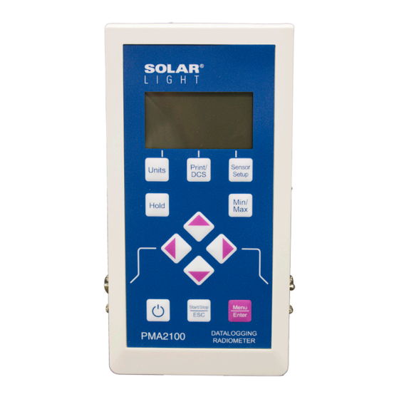
3.2 KEYPAD Figure 7 Keypad Configuration Of The PMA2100 The keys of the PMA2100 (Figure 7) have a tactile feel and an audible signal is generated when the key is pressed. 3.3 AUDIBLE SIGNALS Certain conditions cause the generation of an audible signal to attract The On/Off key toggles the power to the meter. -
Page 8: Setup
Description Of The Problem Detector Conflict Some detectors use all 4 analog inputs available in the PMA2100 and cannot be used simultaneously with other detectors. This message will appear when 2 incompatible detectors are connected to the PMA2100. Upgrade Software The detector requires higher version of the software controlling the PMA2100. -
Page 9: Automatic Datalogging
Select the detector to be set up with keys if two are attached. The measurement made by the PMA2100 can be offset by a user entered value in order to compensate for the drifts in the detector or to Press the SETUP key to enter the “detector setup mode.”... -
Page 10: Alarms
To view or modify the alarm settings, follow these steps: In the DCS mode the PMA2100 is configured to control the Solar Simulators manufactured by Solar Light Company. -
Page 11: Data Management
Connect the PMA2100 to an available serial port on the computer time automatic mode is activated. using the cable provided with the meter. The PMA2100 is capable of logging up to 1,024 data records. Table Turn the PMA2100 ON. 3 illustrates how the logging interval translates to the maximum recording time for a single detector. -
Page 12: Data Processing
Any other response preserves the data. Clearing the data buffer will ensure that only new data points will be downloaded the As an example the steps necessary to import a PMA2100 file into a next time data is retrieved from the PMA. -
Page 13: Interfaces
Both the direct and divided inputs of the other channel are available. If a detector uses more than two analog inputs, then only one detector at a time can be connected to the PMA2100. The detector’s memory has an indication of the inputs used by the detector so the... -
Page 14: Serial And Extension Port
From the Dose Alarm System this modem is connected to the PMA2100. Only the remote modem picking up the calls to the PMA2100 has to be set up in this way. A short pulse (10μs<t<100μs) is generated when the dose integration... -
Page 15: Technical Specifications
If both the value and dose alarms are activated, then the value alarm takes precedence over the dose alarm, i.e. the digital output will be held low as long as the value threshold is exceeded. The optically insulated inputs DIGI1 and DIGI2 control the dose collection on detector port 1 and 2 respectively. -
Page 16: Maintenance
D! J! C 8.2 BATTERY CHARGING L0.123 H1.245 A0.948 The PMA2100 meter can operate directly from the AC line or from 1.234 either rechargeable NiCd or non-rechargeable alkaline batteries. The mW/cm battery compartment holds four AA size cells each with a nominal voltage of 1.2 or 1.5 volts. -
Page 17: Index
Digital Output.........14 Switching..........6 Model Number..........6 Applications..........5 Detectors.............4 Modem Connection........14 Audible Signals..........7 Connecting..........5 Offset............9 Averaging..........8, 11 Setup..........4,6,8,9 ON/OFF............5 Diagnostic...........6 Battery Digital Control Lines........14 PMA2100 Charging..........16 Digital Filter..........8,9 Applications..........5 Display............6 Calendar............8 Design Concept........4 Structure..........6 Calibration..........16 Detectors..........5 Dose............4,6 Clearing The Data........12 Features..........4 Downloading..........11 Clock............7,8 Measuring With........5...
Need help?
Do you have a question about the PMA2100 and is the answer not in the manual?
Questions and answers