Advertisement
Available languages
Available languages
Quick Links
These instructions are to be followed in conjunction with those
found in the IPEX System 636 Installation Guide. The installation
guide is available in every box of System 636 45° Elbows or
on the web at www.ipexinc.com.
System 636 Pipe, Fittings, Termination Kits and Cements are
certified as a system and must be installed as such. Different
manufacturers have different materials, joining systems and
adhesives. Do NOT mix pipe, fittings, cements, or joining
methods from different BH Vent manufacturers, this can result in
unsafe conditions and will void the certification.
System 636 PVC/CPVC concentric vent kits are made from
certified compounds. PVC kits are rated to 65ºC maximum and
CPVC kits are rated to 90ºC maximum.
All termination kits must be located and installed in accordance
with local building code and CSA B149.1 Natural Gas and
Propane Installation Code.
D
45º
C
1
D
System 636 Concentric Vent Kits
Termination Kits Include:
Item #
Concentric Kit
196005
2" x 16"
PVC
196006
3" x 20"
PVC
196105
2" x 28"
PVC
196125
2" x 40"
PVC
196106
3" x 32"
PVC
196116
3" x 44"
PVC
196021
4" x 36"
PVC
197009
3" x 20"
CPVC
197107
3" x 32"
CPVC
197117
3" x 44"
CPVC
197021
4" x 36"
CPVC
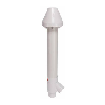
1 Wye - (Concentric)
2 Rain Cap
3 Exhaust Vent Pipe (Inner)
4 Fresh Air Intake Pipe (Outer)
5 Stainless Steel Screw & Nut
IPEX System 636
®
Concentric Vent Termination Kits.
Concentric Vent Kit Assembly
1. Once the proper location has been determined, cut a hole
in the roof or wall large enough to accommodate the outer
pipe. The size of the hole can vary greatly depending on
the roof pitch.
2. As per the procedures outlined in the System 636
Installation Guide , solvent cement the inner pipe to the
concentric Wye fitting.
3. Solvent cement the outer pipe to the concentric Wye fitting.
4. Slide the assembly through the roof or wall penetration.
(Install flashing if needed)
5. To permanently affix the rain cap, it should be solvent
cemented to the inner pipe. For installations where removal
of the cap may be required for service or cleaning the cap, it
can be fastened mechanically (see instructions below). For
either installation method, the outer pipe is only a friction fit
with the cap.
6. Once the rain cap is installed, and the kit secured as outlined
below, the kit can be connected to the venting system.
5
A
G
B
E
3
4
2
Dimension (Inches)
Nominal Pipe Size
✝
A
B*
C
D
E
29.0
16.5
3.5
2
2
36.1
20
4.5
3
3
41.0
28
3.5
2
2
53.0
40
3.5
2
2
48.1
32
4.5
3
3
60.1
44
4.5
3
3
56.0
37.3
6.62
4
4
36.1
20
4.5
3
3
48.1
32
4.5
3
3
60.1
44
4.5
3
3
56.0
37.3
6.62
4
4
B* Dimension be may be shortened to a minimum of 12". Inner pipe (item 3)
must remain "F" inches longer than the outer pipe (item 4). Cut pipe ends
square and solvent cement as outlined in the System 636 installation manual.
✝
C
Installation cutout should be at least 1/2" larger than dimension "C".
Lengthening the units is not permitted.
Canadian Customers
Toll Free: (866) 473-9462
www.ipexinc.com
Installation / Support Procedures
1. Kits must be securely fastened to structure, to ensure dimensions
shown below are maintained.
2. Straps are field supplied. Use straps, clamps or equivalent that
will not score or damage the pipe. Expansion and contraction
should be addressed between appliance and termination point.
3. All penetrations must be sealed according to local building
codes. Caulking for side wall terminations and flashing for roof
penetrations are typical. Use only PVC/CPVC compatible sealing
material, contact IPEX for a complete list.
4. The weight of the concentric kits must be supported by the
clamps/straps and not by the vent system it connects to.
5. Insulating exhaust piping in unconditioned space to prevent
freezing may be required by code.
6. For multiple horizontal installations, keep Concentric Vent Kit
gaps close (up to 4" apart) or over 24" apart.
These guidelines are not appliance specific; OEM manufacturers
may supply spacing guidelines particular to each appliance. In
this case the manufacturer's recommendations shall supersede
those described herein.
To prevent flue gas from recirculating, IPEX recommends installing
multiple concentric kits as follows:
2 concentric vent kits: either maintain a 24" minimum distance
apart, or have the rain caps no more than 4" apart
F
3 concentric vent kits: Option 1 - keep all 3 kits at least 24"
apart. Option 2 - group 2 kits close up to a maximum of 4" apart
and the third kit over 24" apart.
4 or more concentric vent kits: Option 1 - keep all concentric kits
at least 24" apart. Option 2 – group the CVK's in pairs, having 2
kits close together to a maximum of 4" apart, keeping the next
grouping of 2 kits over 24" away. As per Figure C.
The dimensions shown in Fig. C, are distances between the edges
of the rain caps.
7. The pipe length of the concentric vent kit can be shortened;
F
G
providing that the cutting and cementing procedures adhere to
the System 636 guidelines.
7.38
1.75
8. Pipe lengths and/or fittings can added to the socket of the rain
8.75
2.25
cap in order to divert the exhaust gas; providing that the
7.38
1.75
appliance manufacture confirms that the extra length or changing
in direction will not adversely impact the flow of flue gas
7.38
1.75
8.75
2.25
Mechanically Fastened Rain Cap
8.75
2.25
The Rain Cap must be installed with the supplied Stainless Steel
screwand lock nut, and in accordance with the instructions and
10.00
3.50
diagram below.
8.75
2.25
1. Locate the drill location dimple on the outside of the rain cap.
8.75
2.25
2. At this location, drill through the cap and the inner pipe wall.
8.75
2.25
Ensure that the path of the hole is perpendicular to the inner pipe
10.00
3.50
NOT the outside of the cap. For the 2" & 3" kit, drill a 3/16"
hole, for the 4" kit, a 1/4" hole.
3. Insert the screw and tighten the bolt, do not over tighten.
Installation Instructions for 2", 3" and 4"
Wall Termination
Figure A
Clamp or Strap
(Field Supplied)
Exhaust
Air Intake
Exterior wall
Roof Termination
Figure B
Exhaust
Air Intake
Flashing
(Field Supplied)
Exhaust
Sidewall Termination for Multiple Horizontal
Concentric Vent
Figure C: Typical CVK Spacing
4"
MAX
US Customers
Toll Free: (800) 463-9572
www.ipexamerica.com
1" Min
2" Max
(From wall
or Face Plate)
Exhaust
Air Intake
Distance above avg.
snow fall or grade
Ref: CSA B149.1
Distance above avg.
snow fall or grade
Ref: CSA B149.1
Roof
Clamp or Strap
(Field Supplied)
Air Intake
24" MIN
4"
MAX
24" MIN
to next CVK
Advertisement

Summary of Contents for IPEX 196005
- Page 1 Concentric Vent Kit Assembly Installation / Support Procedures found in the IPEX System 636 Installation Guide. The installation 1. Once the proper location has been determined, cut a hole 1. Kits must be securely fastened to structure, to ensure dimensions Figure A guide is available in every box of System 636 45°...
- Page 2 Tronçons de tuyauteries concentriques d’évacuation des Méthodes d’installation/de supportage gaz/d’arrivée d’air – Assemblage figurant dans la Notice d'installation du Système 636 IPEX. On 1. Les ensembles doivent être attachés solidement à la structure afin Figure A trouve la Notice d'installation dans chaque boîte de coudes à...
Need help?
Do you have a question about the 196005 and is the answer not in the manual?
Questions and answers