
Related Manuals for V-TEK PT-55


Summary of Contents for V-TEK PT-55
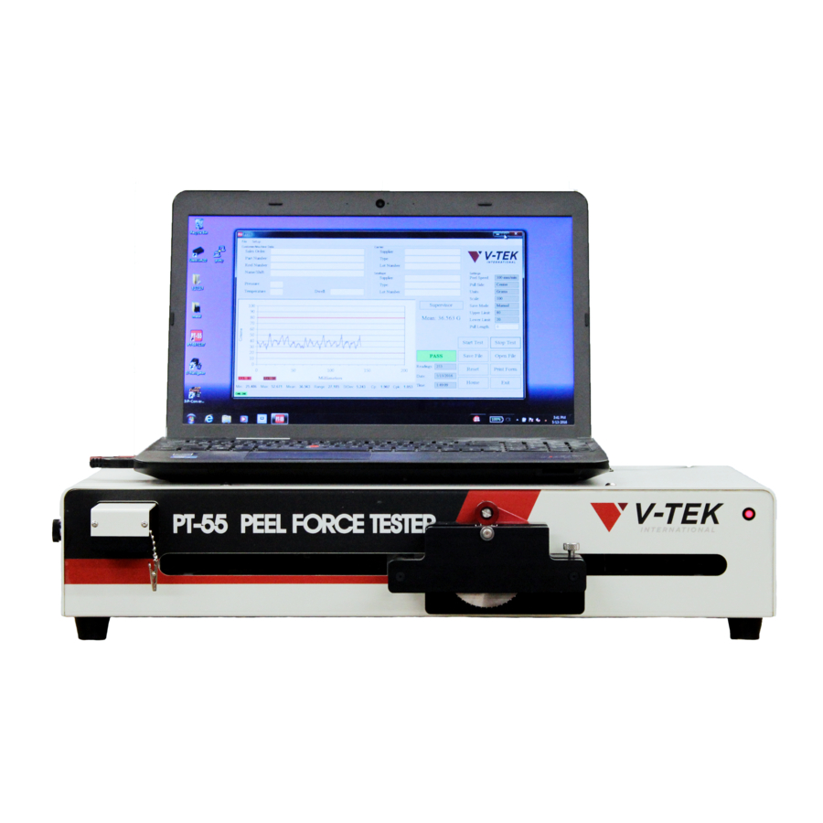
- Page 1 PT-55 SMD Tape Peel Force Tester User’s Guide V-TEK, Inc. 751 Summit Avenue Mankato, MN 56001 (P) 507-387-2039 www.vtekusa.com User’s Guide # D291308.AG...
-
Page 3: Ec Declaration Of Conformity
EC Declaration of Conformity Manufacturers Name: V-TEK Inc. Manufacturers’ Address: 751 Summit Avenue Mankato, MN 56001 USA Declare that the machinery described below complies with applicable health and safety requirements of Part 1 of Annex 1 of the Machinery Directive 2006/42/EC and EMC Directive 2004/108/EC. Confidential technical documentation has been compiled in accordance with Part A of Annex VII of Machinery Directive 2006/42/EC and is available to European national authorities on written request only. -
Page 5: Preface
• A sampling rate of 550 times a second The intended use of the PT-55 SMD Peel Force Tester is to measure the peel force of sealed SMD tape. Use of this equipment in any other way is not recommended. -
Page 6: Machine Details
Machine Details Operating Temperature 0 Degrees Celsius to + 60 Degrees Celsius Although all of the components used on the machine will withstand the temperature range of 0 degrees Celsius to +60 degrees Celsius, such temperature may decrease the life of some of the components. -
Page 7: Intended Use
Intended Use The intended use of the PT-55 SMD Peel Force Tester is to measure the peel force of sealed SMD tape. Use of this equipment in any other way is not recommended. Operating Environment The PT-55 is designed to be operated in a temperature controlled, light, industrial setting. The machine should be installed on a flat, dry, stable surface in a well lit area (ambient lighting of 200 to 300 Lux (Lumens/m2). -
Page 8: General Precautions
Only qualified personnel with the proper technical training, experience working on this type of equipment, and awareness of the possible hazards should perform maintenance on the PT-55. The PT-55 should be installed on a level and stable surface before any operation or maintenance is performed. -
Page 9: Table Of Contents
PT-55 Software ........ - Page 10 Table of Contents (continued) Chapter 3: Operation CONTINUED........25 Configuring &...
-
Page 11: Chapter 1: Machine Overview
Chapter 1: Machine Overview Contents Machine Overview ..........2 Rear Panel . -
Page 12: Machine Overview
The idler wheel holds the carrier tape in place on the tape sprocket. The tape guide holds the carrier tape at the proper angle for a 170-180 degree pullback. Note: The PT-55 is shipped with a carriage clamp attached to the carriage assembly to prevent carriage movement during shipment. -
Page 13: Rear Panel
ON/OFF switch for the PT-55. B. AC Receptacle AC power supply plug. C. (Optional) Security Bracket Security bracket used for securing the laptop to the PT-55. D. USB Port Connector for connecting the PT-55 to a PC. D291308.4f.fm Rear Panel... -
Page 14: Load Cell Details
PT-55 User’s Guide Load Cell Details Figure 1.4 A. Load Cell Position Screw B. Load Cell C. Alligator Clip Load Cell Details D291308.4f.fm... -
Page 15: Carriage Assembly Details
Chapter 1: Getting Started Carriage Assembly Details Figure 1.5 A. Idler Wheel B. Calibration Jig C. Carriage Front Track Guide D. Sprocket Wheel E. Track Adjustment Knob F. Carriage Clamp (remove before operation) D291308.4f.fm Carriage Assembly Details... -
Page 16: Serial Plate
PT-55 User’s Guide Serial Plate The PT-55 Serial plate contains critical machine information including Electrical details, docu- mentation and ratings; model, manufacture date and serial number; and contact information for V-TEK Inc. and the EC Rep for this machine. Serial Plate... -
Page 17: Chapter 2: Setup
Chapter 2: Setup Contents Preparing the Work Area ........8 Laptop Security Bracket Installation. -
Page 18: Preparing The Work Area
The PT-55 is a table-top machine which needs to be placed on a flat, stable surface in a well lit area that is a minimum of 6’ high x 6’ wide x 3‘deep (2m x 2m x 1m). When positioning the PT-55, choose an area that is not located below overhead gantries, walkways or power lines to ensure objects or liquids cannot be dropped on the machine from overhead. - Page 19 Chapter 2: Setup When loading, unloading or running the PT-55, the operator should stand in front of the machine controller to assure easy access to all controls. This position also allows the operator to view all parts of the PT-55 while it is in operation.
-
Page 20: Laptop Security Bracket Installation
800 X 600 capable display. Software: The PT-55 HMI will work on a PC running Windows XP Home (SP3), Windows XP Pro (SP3) or Windows 7. Note: If the computer has issues starting up when the USB ports are in use, see the Appen- dix at the end of this manual for BIOS change instructions. - Page 21 Chapter 2: Setup 2. Remove the thumb screw on the left side of the machine.. Figure 2.2 3. Lift off the top of the PT-55.. Figure 2.3 D291308.5q.fm Laptop Security Bracket Installation...
- Page 22 PT-55 User’s Guide 4. Set the security bracket on top of the PT-55. Put the two 5/16-18 BHCS through the holes of the PT-55 and security bracket. Figure 2.4 5. Tighten the two 5/16-18 nuts on the bolts. 6. Reassemble the top of the PT-55.
-
Page 23: Software Setup
3. Once Net Framework is installed, return to the flash drive and double click S291257 vx.x.x.zip to extract the PT-55 software. 4. Double click S291257 vx.x.x.exe to open the PT-55 InstallShield Wizard. 5. An Application Install screen will appear. Click on Next Figure 2.5... - Page 24 6. The Ready to Install Program screen will open. Click Install. Figure 2.6 7. The Install Shield Wizard Completed screen will open. Click Finish to complete installation.. Figure 2.7 8. The PT-55 Icon will now appear on the desktop. Software Setup D291308.5q.fm...
- Page 25 Chapter 2: Setup PT -55 Driver Installation After the PT-55 software has been installed, the PT-55 USB/Serial Driver must be installed in the laptop that will run the PT-55. 1. Turn the PT-55 ON, then connect the computer to the PT-55 with the USB Cable.
- Page 26 PT-55 User’s Guide Navigate to c:\V-Tek\PT-55\Drivers and unzip the driver files. • Select x64 for 64-Bit OS • Select x86 for 32-Bit OS 5. Within the System Control Panel click Device Manager Figure 2.10 6. As shown below, find the unknown device in the Device Manager. Right click the device and select Update Driver Software.
- Page 27 Chapter 2: Setup 7. In the new window select Browse My Computer for Driver Software and browse to c:\V- Tek\PT-55\Drivers\ x64 Figure 2.12 Note: x64 is based on a 64-bit OS as previously described. For 32-bit systems this location needs to be x86.
-
Page 28: Auto Tension Setup
PT-55 User’s Guide Auto Tension Setup The auto tension feature eliminates having to jog the tape to apply pressure when starting a peel force test. When auto tension is selected and a value is entered, the peel force graph will wait until the auto tension value is reached. - Page 29 Chapter 2: Setup 3. The Supervisor Settings screen will open. Figure 2.16 4. In the System Options section, ensure Auto Ten- sion is Enabled. Enter the Tension Threshold value and the Tension Delay value in milliseconds. The delay is the time from which the carriage assembly starts moving and when the graph starts plotting.
- Page 30 6. The Tensioning message will flash over the graph until the Auto Tension Value is exceeded. Figure 2.18 7. The PT-55 will then automatically reset the graph and begin plotting the peel force test. Figure 2.19 Auto Tension Setup D291308.5q.fm...
-
Page 31: Save Mode Setup
5. If Auto or Auto Sales Order is selected, enter the Auto Save Filename. 6. Select Browse and choose the desired direc- tory in which to save the file. Note: The default save location is C:\V-TEK\PT-55\Setup Files. D291308.5q.fm Save Mode Setup... -
Page 32: Peel Force Test Setup
PT-55 User’s Guide Peel Force Test Setup Note: Although the PT-55 is tested and calibrated during manufacture, the calibration should be re-validated after shipment and prior to first use. Please refer to the validation instructions on page 60. 1. To perform a peel force test, run out a strip of empty, sealed carrier about 6 to 12 inches long. - Page 33 Adjust the thumb screw on the left side of the machine as needed. Note: The PT-55 software must be configured with the correct test parameters before continuing. For test configuration details, see Chapter 3: Software.
- Page 34 PT-55 User’s Guide 7. Press the Start Test button in the Main Screen. The PT-55 will begin moving the carriage and graphing the results. Figure 2.27 8. When complete, the test will stop automatically when it reaches the preset Pull Length. You may also press the Stop Test button when enough data has been gathered to complete the test.
-
Page 35: Chapter 3: Operation
PT-55 Software ........ -
Page 36: Pt -55 Software
Found on included flash drive. Introduction This document provides the basic instructions for operating the PT-55 Peel Force Tester software package. This program will operate the carrier tape drive assembly and generate a graphic dis- play of the peel force required to remove the cover tape. -
Page 37: Menus
Chapter 3: Operation The Main Screen (pictured below) will appear. This screen is used to configure peel tests, set test parameters, perform tests and observe test results. All of the fields will be blank. Figure 3.1 Menus The File Menu is located in the top left corner of the Main Screen. File Menu Selecting Open will allow the operator to select and open a previously saved Master Form. -
Page 38: Customer/Machine Data Fields
Print prints an exact copy of the screen (including the test and customer data). The printout can then be kept for records. Print setup allows the user to select a printer and configure print settings. The Exit command will close the PT-55 Software program. Any unsaved data will be lost. Customer/Machine Data Fields Figure 3.2 The Customer/Machine Data section is used to collect information specific to a particular order. -
Page 39: Carrier Fields
Chapter 3: Operation Carrier Fields Figure 3.3 The Carrier section tracks carrier tape information. Its fields include Supplier, Type, and Lot Number Sealtape Fields The Sealtape section is used to track information about the seal tape (also known as cover tape) that is used in a test. -
Page 40: Peel Test Graph
The graph’s x axis is 100 mm long which corresponds to the X Axis Max- imum value which was set in the Settings section. Note: The PT-55 will read a Pull Length value of 0 as no pull length limit. In this case, the pull length will be the maximum distance of 100mm. - Page 41 Chapter 3: Operation If Auto Tensioning is configured in the Supervisor Settings screen, the graph will appear as below while auto tensioning is in progress. Once Auto Tensioning is complete, the PT-55 will automatically begin the pull test. Figure 3.7 During and after a peel test, the Peel Test Graph displays the test results.
- Page 42 PT-55 User’s Guide The test below shows a test with Moving Average Enabled in the Supervisor Screen. The blue line represents all readings. The pink line represents the moving average. All readings are between the Upper and Lower Limit values, a PASS result.
- Page 43 Chapter 3: Operation The test below shows Moving Average Enabled in the Supervisor Screen. The blue line repre- sents all readings. The pink line represents the moving average. Both the readings and the mov- ing average exceed the Upper Limit value, a FAIL result.
-
Page 44: Auto & Manual Connect
The PT-55's Autoconnect feature looks for a disconnected state every 15 seconds and automat- ically reconnects the PC to the PT-55 if it senses the computer is OFFLINE. While the HMI is reconnecting, a Connecting message will appear in the bottom left corner of the screen. -
Page 45: Peel Test Statistics
Chapter 3: Operation Peel Test Statistics The bar along the bottom of the graph displays a number of values.. Figure 3.12 Minimum peel force from a peel force test. Maximum peel force from a peel force test. Mean The average peel force from a peel force test. Range The minimum peel force test subtracted from the maximum peel force test. - Page 46 Clicking on Save will bring up the screen below. Files are automatically saved in Recipe (*.rcp) format.. Figure 3.14 Choose a name for the file, select a location, and click on OK. The default location is V-TEK\PT- 55\Setup Files. This folder is automatically created when the software is installed. Main Screen Details...
- Page 47 Clicking on Open File will allow the operator to select from any previously saved jobs.. Figure 3.15 Note: Files are automatically saved to a Recipe (*.rcp) for- mat. However, if earlier versions of PT-55 software were used to save files, they will appear as Legacy (*.txt) files. Reset Clicking Reset will prepare the software to perform another test using the same parameters as the test just completed.
- Page 48 Press Home to reset position of carriage for next peel force. Exit The Exit button will close the PT-55 software program. This button can be clicked at any time. All data which has not been saved will be erased. Main Screen Details...
-
Page 49: Supervisor Settings Screen
Chapter 3: Operation Supervisor Settings Screen The Supervisor Settings screen can only be accessed by entering a supervisor password. Click the Supervisor button in the Main Screen to access the Password Input screen and open Supervisor Settings. The Password Input screen will appear. Enter the password at the prompt and click OK. -
Page 50: Customize Main Screen Fields
PT-55 User’s Guide Customize Main Screen Fields Click in the check box next to the field you’d like to edit to open the Change Data window. Figure 3.19 The Change Data window allows the user to customize each field’s Label, Visibility and Input Type. - Page 51 Chapter 3: Operation Enter new text in the Current Label field to customize the field label. In this example, the Sales Order Field has been changed to “SO:” In the Main Screen, the field will now appear as follows: Figure 3.21 Editing Field Visibility The Supervisor Settings screen can also be used to change the visibility of a field.
- Page 52 PT-55 User’s Guide Note: When Not Visible is chosen, all other Change Data fields disappear. Selecting Visible will once again reveal the Label and Input Type fields in the Change Data screen. When Not Visible is selected, the field no longer appears in the Main Screen.
- Page 53 Chapter 3: Operation Operator Input Type When Operator entered is selected, a text box appears next to the field in the Main Screen. This allows the operator to type in the desired information. When the Pressure or Temperature fields are selected, an Operator entered double option appears under Input Type.
- Page 54 PT-55 User’s Guide Constant Input Type When Constant is selected, an Input Choices section appears in the Change Data form. This allows the supervisor to set the field data at a constant value that cannot be changed by the oper- ator.
- Page 55 Chapter 3: Operation Choices Input Type When Choices is selected, an Input Choices section appears in the Change Data form. This allows the supervisor to create a selection drop box for the field. Figure 3.27 To create a drop-down option, enter the desired text in the New Choice field at the bottom of the screen, then press the Enter key.
-
Page 56: Supervisor Settings
PT-55 User’s Guide Supervisor Settings The Supervisor Settings section allows the operator to customize Saving, Test and Graph options and to change passwords. GRAPH OPTIONS The Graph Options section determines how the Peel Test Chart in the Main Screen will function. - Page 57 Chapter 3: Operation When Moving Average is Enabled, the PT-55 will calculate a moving average based on a preset number of sample readings. The Pull Test Graph in the Main Screen can now display a graph with either the raw individual readings (blue) or the Moving Average (pink) or both.
- Page 58 In Sales Order mode, the file is saved to a specific location under the sales order number. Note: The default auto save location is C:\V- TEK\PT-55\Setup Files. This directory is created upon the initial load of the software. Supervisor Settings Screen D291308.7M.fm...
-
Page 59: Display Options
PT-55 will stop, the buttons in the Main Screen will become inactive and the Supervisor but- ton will flash red once the PT-55 is stopped or the test is complete. Normal operation can only resume after the Supervisor Password is entered. - Page 60 Pressing the Change Password button will open the Change Password Screen. Pressing the Calibrate button will place the PT-55 in Calibration Mode, homing the motor and then leading the operator through the calibration process. See Chapter 4 for a detailed descrip- tion of the calibration process.
- Page 61 Chapter 3: Operation Pressing the Validate button will place the PT-55 in Validation Mode which verifies calibration accuracy. See Chapter 4 for a detailed description of the validation process. D291308.7M.fm Supervisor Settings Screen...
- Page 62 PT-55 User’s Guide Save Supervisor Settings Once the Supervisor Settings screen is configured as desired, click Save & Exit to save the settings and return to the Main Screen. Figure 3.28 Supervisor Settings Screen D291308.7M.fm...
-
Page 63: Configuring & Running A Peel Test
Note: For information on machine setup and loading tape, see Chapter 2: Setup. For information on configuring the Main Screen fields, see the previous sections in this chap- ter. 1. Start the application by double clicking the PT-55 Software icon. The Main Screen will open. Figure 3.29 D291308.7M.fm... - Page 64 PT-55 User’s Guide 2. Complete the Customer/Machine Data fields for Name, Part Number, Reel Number, Name/ Shift, and the Temperature, Pressure, and Dwell Time used to create the seal being tested. Figure 3.30 3. Enter carrier tape information in the Carrier fields for Supplier, Type, and Lot Number.
- Page 65 Chapter 3: Operation 5. Enter the Peel Test Settings. These are set in the Supervi- sor Settings screen. Click the Supervisor button to access the Password Input screen and open Supervisor Settings. The Password Input screen will appear. Enter the password at the prompt and click OK. Note: The default password is “password”.
- Page 66 PT-55 User’s Guide 7. In the Main Screen, type in the desired pull length in the Pull Length field. Pull Length should be set between 0-200 mm. Note: If the Pull Length is set to 0, the pull test will default to the X Axis Maximum which was set in the Supervisor Settings screen.
- Page 67 Chapter 3: Operation 10. Click the Start Test button to begin the peel force test. Test results will be displayed on the Peel Force Test Graph and in the fields below the graph. Figure 3.37 11. Click Stop Test to end the test at any point, or simply wait for test to com- plete itself.
- Page 68 PT-55 User’s Guide 12. A PASS or FAIL message will appear at the bottom of the Main Screen. Figure 3.38 13. After the pull test is complete it may be saved or printed using the buttons on the bottom cor- ner of the Main Screen.
-
Page 69: Master Forms
Creating a Master Form 1. Start the PT-55 software by double-clicking the PT-55 icon. The Main Screen will open. Figure 3.40 2. Fill out all the appropriate information and set all the parameters to be used. - Page 70 PT-55 User’s Guide 4. The Save screen will open.. Figure 3.41 5. Enter a file name and press SAVE. 6. To retrieve the master form later, click Open File and select the desired file. A new test can now be run using the previously entered and saved test parameters.
-
Page 71: Creating An *.Csv Export File
Creating an *.csv Export File After the desired data has been set in the user fields and a test has been performed, the PT-55 Software can save test data to a Comma Separated Value (.csv) format. This file is an Excel compatible data file which may be used to create a spreadsheet which can then be customized as desired. - Page 72 PT-55 User’s Guide 3. The peel force test results will be saved to a Comma Separated Value (.csv) format. This document can be opened in a text file reader such as WordPad or imported into an Excel Spreadsheet. A sample .csv text file is pictured below..
-
Page 73: Creating An *.Maf Export File
Creating an *.maf Export File After the desired data has been set in the user fields and a test has been performed, the PT-55 Software can save test data to a Moving Average File (.maf) format. This file is an Excel com- patible data file which may be used to create a spreadsheet which can then be customized as desired. - Page 74 PT-55 User’s Guide 3. The peel force test results will be saved to a Moving Average File (.maf) format. This docu- ment can be opened in a text file reader such as WordPad or imported into an Excel Spread- sheet. A sample .maf text file is pictured below.
-
Page 75: Customizing The Main Screen Logo
Chapter 3: Operation Customizing the Main Screen Logo The V-TEK logo on the Main Screen can be replaced with a customer’s own logo. This may be desirable if peel test results are being printed directly from the screen and sent to customers. - Page 76 PT-55 User’s Guide Customizing the Main Screen Logo D291308.7M.fm...
-
Page 77: Chapter 4: Maintenance & Calibration
Chapter 4: Maintenance & Calibration Contents Recommended Maintenance ........68 Calibration . -
Page 78: Recommended Maintenance
No advance speed calibration is necessary. Advance speeds are microprocessor controlled. Accuracy & Calibration The expected accuracy of the PT-55 is +/- 3.0 grams of the full scale value of the load cell. The load cell range is 0-200 grams. -
Page 79: Calibration
Chapter 4: Maintenance & Calibration Calibration Equipment Required: • 50 gram weight • 100 gram weight • 200 gram weight Figure 4.1 Note: Calibration weights sold separately. Calibration Procedure In the event that the load cell is replaced or if it is part of a maintenance routine, the load cell can be recalibrated by following the steps outlined. - Page 80 PT-55 User’s Guide 2. The Password Input screen will appear.. Enter the password at the prompt then click OK. Figure 4.3 Note: The default password is: password. 3. The Supervisor Settings screen will open. Figure 4.4 4. Click Calibrate. The following message will appear. Click OK.
- Page 81 Chapter 4: Maintenance & Calibration 5. Follow the instructions that appear on the screen. The first is to remove any objects from the load cell clip.. Figure 4.6 6. Once the load cell clip is empty, place the clip on top of the load cell to remove any downward force on the load cell.
- Page 82 PT-55 User’s Guide Ensure the weight is suspended from the center of the calibra- tion jig bearing and is stabilized (not swinging) to ensure accu- rate calibration. Figure 4.9 Note: Hang weights over the calibration jig in the front of the carriage assembly before con- necting them to the load cell clip.
-
Page 83: Verify Calibration Accuracy
Chapter 4: Maintenance & Calibration Verify Calibration Accuracy 1. Click Validate to verify the calibration.. Figure 4.11 2. The following message will appear. Figure 4.12 3. Click OK, then click Save & Exit to return to the Main Screen.. D291308.6r.fm Verify Calibration Accuracy... - Page 84 5. Ensure the carriage is in the home position, then hang a 50g or 100g weight from the load cell, suspending it over the calibration jig just as it was during the calibration process. Figure 3.14 6. Click the Validate button.The PT-55 will begin the validation test. Verify Calibration Accuracy D291308.6r.fm...
- Page 85 Chapter 4: Maintenance & Calibration Observe the graph results and readings to the right of the graph and below it. Figure 4.15 7. Let the chart record at least 50mm of travel then press Stop Test. 8. The Mean value is displayed under the graph. It should be (+/-) 3g from the nominal value of the weight used..
- Page 86 PT-55 User’s Guide Once validation is complete the dialog screen on the right will appear. Select No to exit Validation Mode. Verify Calibration Accuracy D291308.6r.fm...
- Page 87 Appendix A: Changing the Computer BIOS Setting Appendix A Changing the Computer BIOS Setting D291566.1.fm...
- Page 88 Appendix A: Changing the Computer BIOS Setting Appendix A: Changing the Computer BIOS Setting Some computers may need to have their BIOS reconfigured to ensure they will not startup from the USB ports. If your computer is not booting up correctly at startup, remove any USB connections and attempt to start the system again.
- Page 89 Appendix A: Changing the Computer BIOS Setting 6. Press F6 three times to move ATA HDD0 to the top position on the list as shown below. 7. Press F10 to save this setting and exit Boot Options. 8. The Setup Confirmation dialog will open. With Yes highlighted press the Enter key. The computer is now ready for operation.
- Page 91 49 driver installation 15-17 laptop security bracket installation 9 laptop power supply (optional) 3 export file 49, 61-64 offline 34 features i online 34 field operating environment iii visibility 41 input choices 42, 44-45 graph 30-33, 46-47 PT-55 Index D291308.8g.fm...
- Page 92 8, 10-12 software 13-14 auto tension 18-20, 31, 48 save mode 21 peel force test 6, 22-24 software requirements 10 setup 13-14, 26-60 speed calibration 68 spreadsheet 61-64 sprocket wheel 5 start test 36, 57 statistics 35 PT-55 Index D291308.8g.fm...
- Page 93 217211 Feet, poly 250052 Idler wheel 250077 Idler Arm 258974 Drive sprocket 262795 Adjustment knob,.500” 291249 Load Cell Assembly (Replacement) Accessories 105078 Mass set with calibration 291483 Netbook with security bracket D291427h.fm Page 1 of 1 PT-55 Spare Parts List...
- Page 94 D291427h.fm Page 1 of 1 PT-55 Spare Parts List...
- Page 95 I S I & : ) s...
- Page 96 & : ) s...
- Page 97 & : ) s...
- Page 98 & : ) s...
- Page 99 I F I " 0 & : ) s...
- Page 100 " 8 " 6 & : ) s...
- Page 101 " 2 & : ) s...
- Page 102 & : ) s...
- Page 103 I S I & : ) s...
- Page 104 & : ) s...
- Page 105 751 Summit Avenue Mankato, MN USA 56001 Website: www.vtekusa.com Email: service@vtekusa.com Phone: (507) 387-2039 For inquiries regarding spare parts, tape and reel supplies, or the ser- vice department, please call or write: Phone: (507) 387-2039 Email: service@vtekusa.com Please provide the machine model and serial numbers with all inquiries. NOTES ____________________________________________________________ ____________________________________________________________...
- Page 106 Service and Parts Contacts 61053915.fm Page 2...
- Page 107 Load Cell Exploded View Pages 1-2 291249.slddrw Service and Parts Contacts Page 1 of 1 61053915.fm This document D291308.9ag.fm Warranty Document Page 1 of 1 WI201.16, Rev. 4 Back Sheet Page 1 of 1 D291308.10b.fm PT-55 Document List D291308.9ag.fm Page 1 of 1...
- Page 109 12. The warranty applies only to normal use of the equipment and shall be void if V-TEK determines that defects in or failures of the equipment were caused by the Customer’s negligence including the lack of proper preventative maintenance, misuse or accident or by unauthorized repair, alteration or installation.
- Page 112 751 Summit Avenue Mankato, MN 56001 (507) 387-2039 FAX: (507) 387-2257 www.vtekusa.com Email: info@vtekusa.com...
Need help?
Do you have a question about the PT-55 and is the answer not in the manual?
Questions and answers