Table of Contents
Advertisement
U S E R M A N U A L
Entry Level Models
Standard Models
HT C02 - Compact Computer
Standard Models: HT C02Hx STC-yzz-wzzz
Entry Level Models: HT C02HI STC-yzz-wzzz
where x=CPU type, y=OS, w=Power Input (AC or DC), z=configuration
User Manual HT C02
Updated: 23 Feb 2018
Doc Id: INB10042-4 (Rev 08)
Created: 363
Approved: 6987
Please visit www.hatteland-display.com for the latest electronic version of this manual.
Hatteland Display AS, Eikeskogvegen 52, N-5570 Aksdal, Norway
Tel: (+47) 4814 2200 - mail@hatteland-display.com - www.hatteland-display.com
Advertisement
Table of Contents

Summary of Contents for Hatteland HT C02Hx STC series
- Page 1 Updated: 23 Feb 2018 Doc Id: INB10042-4 (Rev 08) Created: 363 Approved: 6987 Please visit www.hatteland-display.com for the latest electronic version of this manual. Hatteland Display AS, Eikeskogvegen 52, N-5570 Aksdal, Norway Tel: (+47) 4814 2200 - mail@hatteland-display.com - www.hatteland-display.com...
- Page 2 Copyright © 2018 Hatteland Display AS Eikeskogvegen 52, N-5570 Aksdal, Norway. All rights are reserved by Hatteland Display AS. This information may not, in whole or in part, be copied, photocopied, reproduced, translated or reduced to any electronic medium or machine- readable form without the prior written consent of Hatteland Display AS.
-
Page 3: Table Of Contents
Contents Contents ..................3 Contents of package ....................... 6 General ..................9 About this manual ......................... 10 About Hatteland Display ....................... 10 www.hatteland-display.com ....................10 Contact Information ......................10 Computers introduction ......................11 Product Labels (Examples) ....................12 Serial Number and Operating System (OS) license label placement ......12 Installation ................ - Page 4 Contents Specifications ................. 47 Specifications - HT C02Hx STC-yzz-wzzz ................48 Standard Models ......................48 Specifications - HT C02HI STC-yzz-wzzz ................49 Entry Level Models ......................49 Specifications Factory Options..........51 Specifications - COM Module RS-232 .................. 52 PCA100294-1 ........................52 Specifications - NMEA / IEC COM Module RS-422 / RS-485 ..........
- Page 5 Contents Appendixes ................75 BIOS - Hybrid Multi Monitor Configuration ................76 BIOS - On-board COM Ports Configuration ................. 78 BIOS - How to create RAID volume ..................81 SSD Selection Guide ......................85 Pinout Assignments ......................88 Trouble-shooting ........................92 Declaration of Conformity .....................
-
Page 6: Contents Of Package
Note: To use this DVD disc you will need an external USB CD/DVD drive or Windows® provide means of getting contents copied over via USB memory stick/network Operating Systems to the operating system. You can alternatively download the drivers from our MEDIA STD01 website www.hatteland-display.com ...list continues on next page... IND100207-17... - Page 7 Contents of package 1 pcs - Würth 742 712 21 This ferrite is required when using 100/110/115V AC voltage on the power supply (not required for 230V AC) to be fully compliant with type approvals. Review installation chapter for more information. Würth 742 712 21 (split, 10.5mm) Mounting brackets incl.
- Page 8 This page left intentionally blank...
-
Page 9: General
General... -
Page 10: About This Manual
About Hatteland Display Hatteland Display is the leading technology provider of specialized display and computer products, delivering high quality, unique and customized solutions to the international maritime, naval and industrial markets. -
Page 11: Computers Introduction
2U and 4U solutions. We continually develop our computers portfolio to make the best use of emerging computer technology so you can be sure that your Hatteland Display computer offers the power needed to run modern applications, with the flexibility to be installed wherever you want, for any marine use. -
Page 12: Product Labels (Examples)
Product Labels (Examples) Product Labels (Examples) Serial Number and Operating System (OS) license label placement Only present if the unit was delivered with factory installed Operating System (OS) such as Microsoft® Windows® Embedded Enterprise. Label size is 7cm wide x 2.8cm high. The same Product Key is also printed on the “Product Declaration”... -
Page 13: Installation
Installation... -
Page 14: Installation And Mounting Of Computers
The classification is only valid for approved mounting brackets provided by Hatteland Display. The unit shall be mounted stand-alone without any devices or loose parts placed at or nearby the unit. Any other type of mounting might require test and re-classification. -
Page 15: Ferrite
General Installation Recommendations Ferrite The ferrite prevent high frequency electrical noise (radio frequency interference) from exiting or entering the equipment. This ferrite is required when using 100/110/115V AC voltage on the power supply (not required for 230V AC) to be fully compliant with type approvals. The ferrite should be mounted (clipped in place on the cable) and located as close as possible to the connector piece that connects to the rear of computer. -
Page 16: Computer Upgrade Precaution Note
3. A one megaohm resistor, installed in the wrist connection end of the ground cord, is a safety requirement. 4. Hatteland recommend to use an Static-dissipative ESD work mat positioned at the workplace. The 3M™ 8501 Portable Field Service Kit is a good choice for this purpose. Make sure that the mat, operator and product is wired/ grounded together. -
Page 17: General Installation Recommendations
General Installation Recommendations Configuring DC power input housing connector Note: Only applicable for DC models! FIG 3 For installations that require DC power input, use the provided FIG 1 2-pin DC Power Input housing with internal cable screw terminal. 1: Open the housing 2: Unmount the fasteners. -
Page 18: Housing / Terminal Block Connector Overview
Connector used for module 4-pin BCZ 3.81/04/180F SN BK BX • CAN Interface (ZIA0001310-B) Screwdriver: 0.4x2.5mm DIN 5264. Identifi ed on Hatteland Display product data sheet as: “Terminal Block 3.81” Tightening torque min.. 0.2 Nm. Tightening torque max. 0.25 Nm. └ Reference: http://catalog.weidmueller.com/catalog/Start.do?localeId=en&ObjectID=1792970000... - Page 19 General Installation Recommendations Configuring Housing / Terminal Block connectors Below is a brief illustration that might be useful during configuration and installation of such connectors. You will need suitable pre-configured cable(s) and tools to configure the connector(s) and cable(s) that are present in your installation environment.
-
Page 20: Cabinet Cover Removal
General Installation Recommendations Cabinet cover removal Note: Areas of interest are marked in this section with arrows in color. Please disconnect ALL cables from the computer unit before proceeding! Procedure applies for HT C02H, HT C02HI and HM C02HK models. 1: Unscrew 3 screws from top of cabinet. -
Page 21: Installing Pci / Pcie Card / Rework Pci Bracket Options - Notice
General Installation Recommendations Installing PCI / PCIe Card / Rework PCI Bracket Options - Notice All factory options are done in-house by our production facility prior to delivery. If you however need to install your own PCI/PCIe cards later and any of the PCI Bracket Options are already pre-installed, please review: “Physical Connections/ Added functionality through 4 x PCI Sized Metal Brackets”... -
Page 22: Pci / Pcie Card Removal / Replacement - Introduction
General Installation Recommendations PCI / PCIe Card removal / replacement - Introduction Note: Areas of interest are marked in this section with circles and arrows in color. Please disconnect ALL cables from the computer unit before proceeding! Procedure applies for HT C02H, HT C02HI and HM C02HK models. -
Page 23: Ht 00229Opt-A1 (Pci / Pcie Card Bracket, Removal & Replacement) Hl/Fh
General Installation Recommendations HT 00229OPT-A1 (PCI / PCIe Card Bracket, Removal & Replacement) HL/FH Note: Areas of interest are marked in this section with circles and arrows in color. Please disconnect ALL cables from the computer unit before proceeding! Procedure applies for HT C02H, HT C02HI and HM C02HK models. -
Page 24: Ht 00275Opt-A1 (Pci / Pcie Card Bracket, Removal & Replacement) Hl/Fl/Hh
General Installation Recommendations HT 00275OPT-A1 (PCI / PCIe Card Bracket, Removal & Replacement) HL/FL/HH Note: Areas of interest are marked in this section with circles and arrows in color. Please disconnect ALL cables from the computer unit before proceeding! Procedure applies for HT C02H, HT C02HI and HM C02HK models. For Half Length (HL) + Full Length (FL) / Half Height (HH) - PCI / PCIe cards Place the EN60945 Tested Bracket as shown on top edge of card and under the top bracket. -
Page 25: Internal Hard Drive (Hdd) Removal / Replacement (Entry Level Models Only)
General Installation Recommendations Internal Hard Drive (HDD) removal / replacement (Entry Level Models only) Note: Areas of interest are marked in this section with circles and arrows in color. Please disconnect ALL cables from the computer unit and HDD’s before proceeding! 2: Push each side of the bracket, one forward and one 1: Unscrew 4 screws on each side of the PCI bracket. -
Page 26: Dvd/Cd Drive Removal / Replacement (Standard Models Only)
General Installation Recommendations DVD/CD Drive removal / replacement (Standard Models only) Note: Areas of interest are marked in this section with circles and arrows in color. Please disconnect ALL cables from the computer unit and DVD/CD drive before proceeding! 1: Unscrew 1 thumb screw on the DVD/CD bracket. 2: Gently pull out the DVD/CD bracket away. -
Page 27: Air Filter Removal / Replacement (H733S30Q20-Sp000-0) - Alternative #1
General Installation Recommendations Air Filter removal / replacement (H733S30Q20-SP000-0) - Alternative #1 Note: Areas of interest are marked in this section with circles and arrows in color. Please disconnect ALL cables from the computer unit and cards before proceeding! Procedure applies for HT C02H, HT C02HI and HM C02HK models. -
Page 28: Air Filter Removal / Replacement (H733S30Q20-Sp000-0) - Alternative #2
General Installation Recommendations Air Filter removal / replacement (H733S30Q20-SP000-0) - Alternative #2 Note: Areas of interest are marked in this section with circles and arrows in color. Please disconnect ALL cables from the computer unit and cards before proceeding! Procedure applies for HT C02H, HT C02HI and HM C02HK models. -
Page 29: Front Fan Removal / Replacement
General Installation Recommendations Front Fan removal / replacement Note: Areas of interest are marked in this section with circles and arrows in color. Please disconnect ALL cables from the computer unit before proceeding! Procedure applies for HT C02H, HT C02HI and HM C02HK models. -
Page 30: Mounting Brackets For Console Mounting - Ht 00226 Opt-A1
General Installation Recommendations Mounting Brackets for Console Mounting - HT 00226 OPT-A1 Note: The unit comes with mounting brackets and screws for console mounting in the package. Please review specifications and “Technical Drawings - Accessories” chapter in this user manual for additional information. Procedure applies for HT C02H, HT C02HI and HM C02HK models. -
Page 31: 19 Inch Rack Kit 4U - Ht 00223 Opt-A1
19 inch Rack Kit 4U - HT 00223 OPT-A1 Note: The unit can also be mounted inside a Hatteland Display 4U cabinet for rack mounting purposes. Please review specifications and “Technical Drawings - Accessories” chapter in this user manual for additional information. -
Page 32: Replacing Internal Cmos Battery
General Installation Recommendations Replacing Internal CMOS Battery Note: Areas of interest are marked in this section with arrows in color. Please disconnect ALL cables from the computer unit before proceeding! Procedure applies for HT C02H, HT C02HI and HM C02HK models. NOTE: All BIOS settings, Date and Time will be lost if battery is removed from motherboard. - Page 33 General Installation Recommendations 5: Locate CMOS battery as indicated near the smallest 6: With a finger/nail, push the metal clip inwards as PCI-E slot (just above it). indicated (1) and the battery will pop up automatically (2). 7: Carefully grab the battery with finger/nail and remove 8: Place the NEW battery as aligned in the lower part it from the holder.
-
Page 34: Physical Connections
Physical Connections Front area of computer models 12cm FAN intake+filter Standard Entry SSD/HDD Power LED SSD/HDD Activity LED Power LED USB2.0 DVD/CD-RW USB2.0 Power Button Reset Button 2.5” Removable SSD/HDD Trays. Power Button Power LED Reset Button Device Order: #3 (at top), #2, #1 and #0 at bottom AIR FILTER: The computer unit features an cleanable / replaceable air filter located in front behind the metal hatch. - Page 35 Single Front Removable Tray and Pre-mounted Storage indicated. Replace or remove the device as needed. Make Device are available from Hatteland Display as accessory. sure the device connects with the interface connector located in the end of the tray prior to fastening screws.
- Page 36 Physical Connections Connector area of computer - Standard and Entry Level Models Expansion / Module Area PCIe x16 Power Input AC PCIe x4 Power Input DC PCIe x1 Expansion Area for 4 x PCI Brackets Grounding Screw RS-485/422 COM2 DVI-D USB2.0 2 x Network 2 x Network...
- Page 37 Physical Connections 1 x DisplayPort (DP) OUTPUT: Connect your DP (male) cable to the DisplayPort (v1.2) 20P connector (female) on the rear side of the unit. The DP has its own locking mechanism that locks the plug inserted. Make sure the plug “clicks” into place to verify a proper and secure connection.
- Page 38 Physical Connections 3 x PCIe + 1 x PCI Slots: Supports Full Height and Full Length Profile cards. Cards are normally installed from factory. Please review the General Installation Recommendations chapter in this manual for more information. Additionally consult the 3rd party manual available on the attached documentation CD delivered with this unit.
-
Page 39: Pci Bracket Expansion Matrix
Sized Metal Bracket options as suggested numbered position queue below. Make sure that slots counting from 1 to max 4 are occupied in an incremental manner. This is to keep the placement of cards and brackets in consistency with current factory default delivered units from Hatteland Display. Available Bracket Options:... - Page 40 Physical Connections 4 x EXPANSION AREA for Optional Modules: The HT C02 computers supports a multitude of combinations and gives additional features to the unit by taking advantage of the 4 available expansion areas. The table below lists all modules currently available for factory mounting - including combinations and duplicates of each module possible (see next page).
- Page 41 Physical Connections Lower Row Modules - Options (review dedicated Datasheets in this manual): # Illustration Module Code ID Description / Function COM non-isolated RS-232, 4 channel Module Connectors: 4 x D-SUB 9P Male Typenumber: PCA100294-1 RS-422/RS-485 NMEA Isolated / ECDIS Module 4 x 5-pin Terminal Block 3.81 connection NMEA COM Typenumber: PCA100293-1...
-
Page 42: Module Expansion Matrix
Physical Connections Module Expansion Matrix Table below indicates how many duplicates of the same module can be installed at the same time. Due to limited number of internal connectors, different upper/lower area size and technical limitations some combinations (with duplicates) are naturally not possible to achieve. Colored Table Cell refers to the “Upper Row”... - Page 43 Physical Connections NMEA COM Default Factory Mounting Position (upper row / lower row) IND100133-56...
- Page 44 Physical Connections NMEA COM Default Factory Mounting Position (upper row / lower row) IND100133-56...
-
Page 45: Factory Preset Com Port Numbering
Factory Preset COM Port Numbering Hatteland Display offer a wealth of options resulting in many Operating System numbered COM ports. The table below lists all known ports that are assigned if a specific factory option (or duplicates of them) were factory mounted prior to manufacturing and delivery of units to customer. - Page 46 This page left intentionally blank...
-
Page 47: Specifications
Specifications... -
Page 48: Specifications - Ht C02Hx Stc-Yzz-Wzzz
Please visit www.hatteland-display.com for the latest electronic version. Note: All specifications are subject to change without prior notice! Please visit www.hatteland-display.com for the latest electronic version. T E C H N I C A L D E S C R I P T I O N... -
Page 49: Specifications - Ht C02Hi Stc-Yzz-Wzzz
Please visit www.hatteland-display.com for the latest electronic version. Note: All specifications are subject to change without prior notice! Please visit www.hatteland-display.com for the latest electronic version. T E C H N I C A L D E S C R I P T I O N... - Page 50 This page left intentionally blank...
-
Page 51: Specifications Factory Options
Specifications Factory Options... -
Page 52: Specifications - Com Module Rs-232
4 channel COM RS-232, DB9M COM Module Description: The Hatteland Display COM modules provide the system with quad independent COM channels. The module is attached to the motherboard via standard USB interface. Application software access the COM channels as standard COM devices, i.e. in the normal case is there no requirements for additional software development. -
Page 53: Specifications - Nmea / Iec Com Module Rs-422 / Rs-485
4 channel RS-422 / RS-485, NMEA / IEC COM Module Description: The Hatteland Display COM modules provide the system with quad independent COM channels. The module is attached to the motherboard via standard USB interface. Application software access the COM channels as standard COM devices, i.e. in the normal case is there no requirements for additional software development. - Page 54 3. A one megaohm resistor, installed in the wrist connection end of the ground cord, is a safety requirement. 4. Hatteland Display recommend to use an Static-dissipative ESD work mat positioned at the workplace. The 3M™ 8501 Portable Field Service Kit is a good choice for this purpose.
- Page 55 (The “isolated Ground” wire will help absorb this energy). For slow changing or DC offset our system will most likely work without the ground wire. Hatteland Display recommends connecting the ground wire since it will help protect the system in event of fast transient and most likely also help improve signal integrity in the system.
-
Page 56: Specifications - Can Module With Co-Processor
Series X / Series X G2 8, 12, 13, 15, 17, 19, 24, 26 inch Panel Computers and selected Stand-alone Computers. The Hatteland Display CAN Module is delivered with software download functions and standard API, SAE J2534, which allow the user to add their own functions, such as real time critical functions, and high level CAN protocol. -
Page 57: Specifications - Isolated Digital Input/Output Module
Description: The Hatteland Display DIO modules provide the system with 4 isolated digital output and 4 isolated digital input. The module is attached to the motherboard via USB interface. Application software access the DIO channels via D2XX interface provided by the chip manufacturer, i.e. - Page 58 (MC 1,5/ 5-STF-3,81) Terminal Block 3.81 (see illustration below) • Test and certi cate Hatteland Display standard, (tested / type approved by the following classification societies): IEC 60945 4th (EN 60945:2002), IACS E10, EU RO MR - Mutual Recognition • Safety IEC60950 The DIO module is intended to be used in control circuits and does therefore need external fuse to meet safety agency approvals.
-
Page 59: Specifications - Lan Module
2 x LAN RJ-45 - Internal Module Description: The Hatteland Display USB->Ethernet module provide the system with dual independent Ethernet ports. The module is connected internally to the motherboard via standard USB interfaces. Application software access the ethernet channels as standard ethernet devices, i.e. -
Page 60: Specifications - Isolated Com Module Rs-232
2 channel COM RS-232, DB9M COM Module Description: The Hatteland Display COM modules provide the system with dual independent COM channels. The module is attached to the motherboard via standard USB interface. Application software access the COM channels as standard COM devices, i.e. in the normal case is there no requirements for additional software development. -
Page 61: Specifications Accessories
Specifications Accessories... -
Page 62: Specifications - External Modules (Usb)
This provides flexibility for new installations and easy upgrade of already installed systems. In fact, any Hatteland Display product that has a USB2.0 port can take advantage of these External Modules for both legacy, obsoleted, current and future products as long as the software and firmware supports the Operating System. - Page 63 Specifications - External Modules (USB) All specifications are subject to change without prior notice! SPECIFICATIONS Note: All specifi cations are subject to change without prior notice! Please visit www.hatteland-display.com for the latest electronic version. Ordering Details: TypeNumber Description Internal Speci cations (link to separate datasheets)
- Page 64 This page left intentionally blank...
-
Page 65: Technical Drawings
Technical Drawings... -
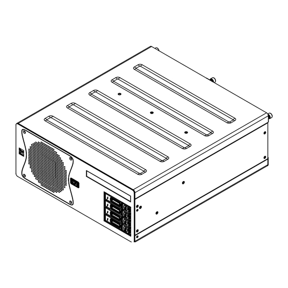
Page 66: Technical Drawings - Ht C02Hx Stc-Yzz-Wzzz
Technical Drawings - HT C02Hx STC-yzz-wzzz Standard / Entry Level AC models IND100132-268... -
Page 67: Technical Drawings - Accessories
Technical Drawings - Accessories... -
Page 68: Technical Drawings - 19" Rack Kit 4U
Technical Drawings - 19” Rack Kit 4U HT 00223 OPT-A1 IND100132-269... - Page 69 Technical Drawings - 19” Rack Kit 4U HT 00223 OPT-A1 IND100132-269...
-
Page 70: Technical Drawings - Mounting Brackets
Technical Drawings - Mounting Brackets HT 00226 OPT-A1 IND100132-270... -
Page 71: Technical Drawings - En60945 Pci/Pcie Support Bracket
Technical Drawings - EN60945 PCI/PCIe Support Bracket HT 00275 OPT-A1 IND100132-276... -
Page 72: Technical Drawings - External Modules (Usb)
Technical Drawings - External Modules (USB) IND100132-245... -
Page 73: Technical Drawings - 20" Slide Rails (For 19" Rack)
Technical Drawings - 20” Slide Rails (for 19” Rack) HT 00224 OPT-A1 IND100132-278... -
Page 74: Technical Drawings - 26" Slide Rails (For 19" Rack)
Technical Drawings - 26” Slide Rails (for 19” Rack) HT 00225 OPT-A1 IND100132-279... -
Page 75: Appendixes
Appendixes... -
Page 76: Bios - Hybrid Multi Monitor Configuration
BIOS - Hybrid Multi Monitor Configuration Set up onboard signal output simultaneously with PCIe Graphics Card With the following configuration steps in BIOS, the Computer unit's signal outputs (DVI, DisplayPort and VGA) can be used together with optional factory option PCIe Graphics Card to output more than 3 signals at the same time. Reference: Hybrid Multi-Monitor Support from Intel®... - Page 77 BIOS - Hybrid Multi Monitor Configuration 3: Select option "Primary Display" and set to "IGFX" and press enter. Aptio Setup Utility - Copyright (C) 2012 American Megatrends, Inc. Chipset Select which of IGFX/PEG/PCI Graphics Configuration Graphics device should be IGFX VBIOS Version 2173 Primary Display Or select SG for Switchable Gfx.
-
Page 78: Bios - On-Board Com Ports Configuration
BIOS - On-board COM Ports Configuration Low / High Speed How to configure COM1 and COM2 speed mode in BIOS. In high speed mode, the Baudrate goes above 115200 bps. Due to limitation of generic Operating System (OS) Driver, it is required to set 9600 for achieving 128000 in high speed mode. - Page 79 BIOS - COM Ports Configuration 3: Then navigate to "Speed mode" (for the port chosen) and select Low/High Speed based on table below: Aptio Setup Utility - Copyright (C) 2012 American Megatrends, Inc. Advanced Change the speed mode for Serial Port 1 Configuration serial port (Baudrate) Serial Port [Enabled]...
- Page 80 BIOS - COM Ports Configuration COM2 Mode Choose desired COM2 mode from choices: Aptio Setup Utility - Copyright (C) 2012 American Megatrends, Inc. Advanced COM2 mode selection NCT6102D Super IO Configuration NCT6102D Super IO Chip NCT6102D Serial Port 1 Configuration Serial Port 2 Configuration WatchDog Count Mode [Second]...
-
Page 81: Bios - How To Create Raid Volume
BIOS - How to create RAID volume Instructions Before configuring it is assumed the user has the appropriate knowledge on how to enter and navigate within BIOS and change values. When BIOS screen has been accessed, follow the steps below. 1: Go to Advanced / SATA Configuration, and click enter: Aptio Setup Utility - Copyright (C) 2012 American Megatrends, Inc. - Page 82 BIOS - How to create RAID volume During next boot press Ctrl+I to enter RAID Setup when the following menu is displayed: Intel(R) Rapid Storage Technology - Option ROM - 12.5.0.1815 Copyright(C) 2003-13 Intel Corporation. All Rights Reserved. RAID Volumes: None defined.
- Page 83 BIOS - How to create RAID volume Then configure the RAID Volume as you want: Intel(R) Rapid Storage Technology - Option ROM - 12.5.0.1815 Copyright(C) 2003-13 Intel Corporation. All Rights Reserved. CREATE VOLUME MENU NAME: Volume1 RAID1(Mirror) RAID Level: Disks: Select Disks Strip Size: N/A Capacity: 74.5 Sync: N/A...
- Page 84 BIOS - How to create RAID volume Procedure to reset disk mode in Microsoft® Windows® 7 before capturing image: - Open Registry Editor and go to: HKEY_LOCAL_MACHINE\System\CurrentControlSet\Services\ For each of the subkeys: Msahci, iaStorV and iaStor; - Find “Start” string, doubleclick and change value from 3 to 0, if not set. - Exit and shutdown the unit.
-
Page 85: Ssd Selection Guide
SSD Selection Guide Solid State Disk (SSD) Devices Last revised : 22 November 2017 SSD's has many benefits over conventional hard drives, but when it comes to write endurance it is important to choose the technology to be used with care. It is of very high importance to consider several aspects when using an SSD for a particular application, below the most critical ones, such as: - Nature of the application, data written to disk during a defined time period (worst case). - Page 86 SSD Selection Guide Calculation of required size of SSD (Multi-Level Cell - MLC) device) The table below details the write endurance of the an enterprise environment. All values are verified by Hatteland Display during the qualification / selection process. Write Endurance Specifications Write Endurance Specifications Previous 2.5”...
- Page 87 SSD Selection Guide Measure of number of write cycles (Intel® Solid-State Drive Toolbox software) https://downloadcenter.intel.com/Detail_Desc.aspx?agr=Y&DwnldID=18455 Download Software from: Preparation 1: Install "Intel® Solid-Sate Drive Toolbox" at target system. 2: Install the unit in valid configuration, i.e. the application shall running valid use case, if possible use worst case scenario (with respect to disk activity).
-
Page 88: Pinout Assignments
Pinout Assignments Connectors illustrated here are either standard by factory default or may be available (through factory customization). Note that some combinations may not be possible due to space restrictions. List also valid for customized models. All pin out assignments are seen from users Point of View (POV) while looking straight at the connector. Please review the dedicated datasheet or technical drawings for your actual unit to identify and determine the presence of desired connector. - Page 89 Pinout Assignments 18/24/24+5 pin DVI-D, DVI-I, Single Link, Dual Link Combined Female 8-pin RJ45 10/100/1000Mbps LAN/Ethernet 1 2 3 4 5 6 7 8 C1 C2 1 2 3 4 5 6 7 8 9 10 11 12 13 14 15 16 PIN 01 D0P+ Differential Pair 0 (Positive) PIN 02...
- Page 90 Pinout Assignments 10+10 pin Isolated Digital Input/Output Module 3 x 3.5mm (TRS) Jacks (Line in, Line Out, Mic In) Type Number “PCA100297-1” + 9-pin Amplifi ed Mono/Stereo Audio Out, DSUB Female Type Number “VSD100897-1” (PCI Metal Bracket) Module A Module B Line Out Line In Mic In 2 3 4 3 x 3.5mm (TRS) Jack Specifi cation / Connection:...
- Page 91 Pinout Assignments 4+4 pin CAN I/O Module, 2 channels Type Number “ZIA0001310-B” CAN1 CAN2 Pin 01 X8 - Can1: 081 In Low Pin 02 X8 - Can1: 082 Out Low Pin 03 X8 - Can1: 083 In High Pin 04 X8 - Can1: 084 Out High Pin 01 X9 - Can2: 091 In Low Pin 02 X9 - Can2: 092 Out Low Pin 03 X9 - Can2: 093 In High...
-
Page 92: Trouble-Shooting
(HT/HM C01 with WinXP only) or it is included as a image on the USB Flash Kit supporting all Computers and Maritime Panel Computers (MMC) models from Hatteland Display. The recovery image fi le is not accessible from any Operating System (OS), only by the Recovery Kit (USB Flash). The USB Flash will not rescue or... -
Page 93: Declaration Of Conformity
Declaration of Conformity We, manufacturer, Hatteland Display AS, Eikeskogvegen 52, N-5570 Aksdal, Norway declare under our sole responsibility that the JH MMD, JH MMC, JH STD, JH MIL, HM NMD, HM MIL, HM CMD, HT STD, HD MMD, HM MMD, HT MMC, HD MMC and HT/HM (computers) product ranges is in conformity with the following standards in accordance with the EMC Directive. -
Page 94: Return Of Goods Information
Return of goods: (Applies not to warranty/normal service/repair of products) Hatteland Display referenced as “manufacturer” in this document. Before returning goods, please contact your system supplier before sending anything directly to manufacturer. When you return products after loan, test, evaulation or products subject for credit, you must ensure that all accessories received from our warehouse is returned. -
Page 95: General Terms And Conditions
General Terms and Conditions As of January 2015, Hatteland Display AS’ “Terms of Sales and Delivery” and “Warranty Terms” has been substituted by the updated ”General terms and conditions for sale of goods and performance of additional services” (the “General Terms and Conditions”). -
Page 96: Signal Output Combinations
Overview of tested signal outputs The latest computers from Hatteland Display are capable of displaying 3 signals simultaneously via DVI-D, DVI-I or RGB/VGA (via adapter) or through the DisplayPort (DP) (including DP to DVI adapter) connectors. Below, the list of possible combinations the hardware support. -
Page 97: Known Deviations
Approval / Log (all cases in this document) CASE #1 - Rev 01 - 30 Nov 2015 - Joakim Emanuelsson, Director Product Management Appendix Page 1 of 1 IND100077-157 Hatteland Display AS, Stokkastrandvegen 87B, N-5578 Nedre Vats, Norway Tel: (+47) 4814 2200 - mail@hatteland-display.com - www.hatteland-display.com... -
Page 98: Notes
- License Terms for the installed OEM Operating System (OS) can be found in the following default factory paths: Note: This is a general listing for a varity of OS’s Hatteland Display can factory install depending on unit. Please check specification for your unit to verify type of OS installed in order to retrieve the license terms. - Page 99 User Notes Appendix IND100077-24...
-
Page 100: Revision History
- ref: QAR/132866, page 37,94 31 Aug 2017 Removed Factory Option based on Matrox P69 Graphics card throughout the manual, now EOL. Ref: http://www.hatteland-display.com/mails/23_2017_ecn.html 23 Feb 2018 Added chapter for replacement of Motherboard BIOS Battery, page 32,33 Added Factory Option PCA100309-1, page 59,89 General updates performed throughout the manual based on latest company profile and latest revised specifications. - Page 101 Revision History IND100077-151...
- Page 102 w ww .hat tel and-di s p l ay . com...
Need help?
Do you have a question about the HT C02Hx STC series and is the answer not in the manual?
Questions and answers