Table of Contents
Advertisement
Advertisement
Table of Contents

Related Manuals for Stryker X7000

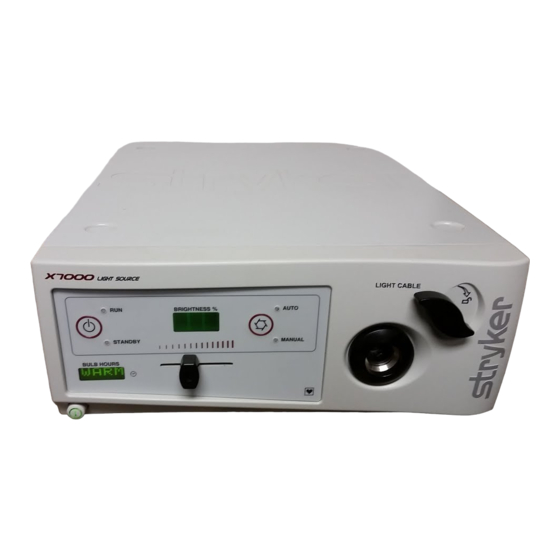
Summary of Contents for Stryker X7000
- Page 2 Warranty Stryker Endoscopy warrants the X-7000 Light Source shall Stryker Endoscopy be liable for any breach of war- against defects in both materials and workmanship to the ranty in any amount exceeding the purchase price of the registered owner at the time of purchase. All components product.
-
Page 3: Table Of Contents
Table of Contents 1.0 INTRODUCTION 1.1 Scope......................................1 1.2 Responsibility...................................1 1.3 Upgrades....................................1 1.4 Equipment Overview................................1 1.5 Service Options..................................1 1.6 Maintenance Precautions................................1 1.7 Factory Service Instructions..............................2 1.8 Required Equipment................................2 1.9 Required Skills..................................2 1.10 Required Replacement Components..........................2 2.0 DIAGNOSTICS AND CORRECTIVE MAINTENANCE 2.1 General Recommendations..............................3 2.2 Power Requirements................................3 2.3 Ambient Requirements................................3 2.4 Connections and Wiring.................................3... - Page 4 4.5 Front Panel Components..............................16 4.5.1 Jaw Handle Replacement...........................16 4.5.2 Potentiometer Knob Replacement........................16 4.5.3 Front Panel Replacement...........................17 4.5.4 Jaw Assembly Replacement..........................17 4.5.5 Power Switch Replacement..........................18 4.5.6 Display Board Replacement..........................18 4.6 Fuse Replacement..................................19 4.6.1 Rear Panel Fuses..............................19 5.0 ELECTRONIC PROCEDURES 5.1 Required Skills..................................20 5.2 Alignment and Calibration..............................20 6.0 FINAL ASSEMBLY AND TESTING 6.1 Required Skills..................................21...
-
Page 5: Introduction
Stryker Endoscopy recommends that these be car- ried out only by qualified technicians with proper test In no event shall Stryker Endoscopy be liable for incidental equipment listed in this manual, so that the safety of oper- or consequential damages in connection with or arising ators and patients may not be compromised. -
Page 6: Factory Service Instructions
Package the X-7000 carefully in the original shipping con- If a repair procedure necessitates replacements parts, tainer, if possible. please refer to the Appendix (page 22). Ship the Stryker Endoscopy X-7000 Light Source, prepaid and insured, to: Stryker Endoscopy Customer Service Attention: Repair Department... -
Page 7: Diagnostics And Corrective Maintenance
2.1 GENERAL RECOMMENDATIONS ensure that all associated signal cabling is cor- rectly installed prior to applying AC power to the The Stryker Endoscopy Model X-7000 Light Source is a system. precision instrument which has been engineered and man- ufactured with great care to ensure the safety of operators and patients. -
Page 8: Repair Checklist And Matrix
3.0 Repair Checklist and Matrix 3.1 INITIAL REPAIR CHECKLIST The following page is intended for use by qualified Stryker personnel only. Complete a copy of the checklist and file it in the DHR. 3.2 REPAIR MATRIX #1 3.3 REPAIR MATRIX #2 The Repair Matrices are intended for use by qualified Stryker personnel only, in conjuction with section 4.0... -
Page 9: Diagnostic Analysis Checklist
5900 Optical Court San Jose, CA 95138 t: 408 754 2000 f: 408 754 2505 Endoscopy www.stryker.com DIAGNOSTIC ANALYSIS CHECKLIST CHECK DATE: _______________NAME: _____________________ SERIAL #: ___________________ What is the customer complaint? General Assembly Check Points Yes/No Details Is there any visual damage on the unit? -
Page 10: Repair Matrix
3.2 REPAIR MATRIX Use the following matrix to identify failure and repair codes. Refer to section 4.0 for repair instructions. REPAIR CODES Error Code Failures Power Failures Power Switch Failure No Power Flashing Power Button BUF "Bulb" in Bulb Hours Power only to Front Panel Light Output Failure NLF No Light Output... -
Page 11: Component Removal And Repair
4.0 Component Removal and Repair 4.1 COMPONENT REPLACEMENT INSTRUCTIONS 4.1.1 Component Removal Table NOTE: All components in previous columns must be Required skills: Basic electronics techniques. removed before removing a component. WARNING: The incorrect use of any of the required tools and techniques may risk damage to the equipment or injury to the person carrying Control... -
Page 12: Individual Replacement Instructions
4.1.2 Individual Replacement Instructions 4.2 CONSOLE COVER REMOVAL NOTE: Before removing any component in the X-7000, Tools Required: the Console Cover must be removed (refer to sec- Basic Tool Kit tion 4.2). • Remove power cord. To remove and repair any of the following components, •... -
Page 13: Power Source Components
4.3 POWER SOURCE COMPONENTS 4.3.1 Control Board Replacement Tools Required: Basic Tool Kit • Remove power cord and console cover (procedure 4.2). • Disconnect connectors and attached wires. • Remove the 5 screws attaching the control board to the ballast. •... -
Page 14: Lamp Ballast Replacement
4.3.2 Lamp Ballast Replacement Tools Required: Basic Tool Kit • Remove power cord and console cover (procedure 4.2). • Remove the control board (procedure 4.3.1). • Label and disconnect the three power input cables located at the rear of the ballast. •... -
Page 15: Ac Inlet Board Replacement
4.3.3 AC Inlet Board Replacement Tools Required: Basic Tool Kit • Remove power cord and console cover (procedure 4.2). • Remove the control board (procedure 4.3.1). • Remove the lamp ballast (procedure 4.3.2). • Remove the 2 bolts from the 2 nuts. •... -
Page 16: Ballast Fan Replacement
4.3.4 Ballast Fan Replacement 4.4 LIGHT SOURCE COMPONENTS Tools Required: 4.4.1 Bulb Fan Replacement Basic Tool Kit Tools Required: NOTE: BOTH fans must be replaced if one fan malfunc- Basic Tool Kit tions. NOTE: BOTH fans must be replaced if one fan malfunc- •... -
Page 17: Bulb Board Replacement
4.4.2 Bulb Board Replacement • Remove power cord and console cover (procedure 4.2). • Remove the bulb. • Remove the bulb fan (procedure 4.4.1). • Remove the 2 wire harnesses. • Remove the bulb board and replace. 4.4.4 Hot Mirror Replacement •... -
Page 18: Motor Mount Replacement
4.4.5 Motor Mount Replacement • Remove power cord and console cover (procedure 4.2). • Remove the bulb (procedure 4.4.1). • Remove the hot mirror (procedure 4.4.4). • Remove the 2 Phillips screws from beneath the hot mir- ror. • Remove the 2 nuts. •... -
Page 19: Motor Replacement
4.4.6.1 Motor Replacement • Remove power cord and console cover (procedure 4.2). • Remove the motor mount (procedure 4.4.5). • Remove the 4 Allen screws. • Remove the motor and replace. • Reinsert the 4 Allen screws. • Replace the motor mount and cover. 4.4.6.2 Integrating Rod Replacement •... -
Page 20: Front Panel Components
4.5 FRONT PANEL COMPONENTS 4.5.2 Potentiometer Knob Replacement 4.5.1 Jaw Handle Replacement • Remove power cord. • Remove power cord. • If potentiometer knob is damaged or detaches from the front panel, but the protruding metal tab is still con- •... -
Page 21: Front Panel Replacement
4.5.3 Front Panel Replacement • Replace all removed components. • Remove power cord and console cover (procedure 4.2). 4.5.4 Jaw Assembly Replacement • Remove the jaw knob and potentiometer knob (proce- • Remove power cord and console cover (procedure 4.2). dures 4.5.1 and 4.5.2,). -
Page 22: Power Switch Replacement
4.5.5 Power Switch Replacement 4.5.6 Display Board Replacement • Remove power cord and console cover (procedure 4.2). • Remove power cord and console cover (procedure 4.2). • Remove the jaw knob and potentiometer • Remove the front panel (procedure 4.5.3). knob (procedures 4.5.1 and 4.5.2). -
Page 23: Fuse Replacement
4.6 FUSE REPLACEMENT 4.6.1 Rear Panel Fuse Replacement Tools Required: Basic Tool Kit • Remove power cord. • Locate the fuse holder below the power cord inlet (see Figure 1). • Release the fuse holder clamps with a flat head screw driver and remove the fuse holder with 2 attached fuses. -
Page 24: Required Skills
5.0 Electrical Procedures 5.1 REQUIRED SKILLS • Basic electronics techniques. • Experience in the operation of an oscilloscope. WARNING: The incorrect use of any of the required tools and techniques may risk damage to the equipment or injury to the person carrying out the procedure, subsequent operators, or patient. -
Page 25: Final Assembly And Testing
Stryker Endoscopy. • If any leakage reading is over 500µA, send the unit to Stryker Endoscopy for repair (refer to procedure 1.6 to • If the unit appears to be operating correctly, proceed to obtain factory service at Stryker Endoscopy). -
Page 26: Hi-Pot Test
6.4 HI-POT TEST • Energize the Hi-Pot tester and adjust the voltage by turn- ing the adjusting knob until the meter reads 1.8KV. • Ensure the Hi-Pot tester is operating properly by touch- ing the positive and negative test leads and listening for the sound emitted. -
Page 27: Appendix
7.0 Appendix 7.1 ASSEMBLY DIAGRAM 7.2 PARTS LISTING 105-199-584 ASSY, X-7000 BOTTOM TRAY 105-199-581 ASSY, X-7000 ELLIPTICAL BULB MODULE 105-199-678 ASSY, COVER, X-7000 105-193-198 SCREW, 6-32 X 0.25 PH EXT. SEMS 7.3 REFERENCE DOCUMENTS • MAP 0337 NOTE: NONE OF THE IN-HOUSE MAPs (Manufac- turing Assembly Procedures), QIPs (Quality Inspection Procedures), SPECIALTY TOOLS, JIGS, OR FIXTURES LISTED IN THIS MAN-... -
Page 28: Warranty
8.0 Warranty This Stryker Endoscopy product is warranted to the original purchaser to be free from defects in material and workmanship for the following times: • One year following the date of delivery and an additional 30 days following repair... -
Page 29: Other Service
10.0 Other Service For service in the U.S.A., call your Stryker Endoscopy Representative. Outside of the U.S.A., please contact your Stryker Endoscopy distributor at one of the following locations: Stryker Corporation Stryker European Rep - RA/QA Manager 2725 Fairfield Road... - Page 30 Stryker Finland Stryker Middle East / Africa PL 80 (Makelankatuz) Via Della Posta FIN 00501 Helsinki 6934 Bioggio FINLAND Switzerland Phone:358 (0) 9 7744 680 Phone:(4021) 212-1122 Fax:358 (0) 9 7744 6820 Fax:(4021) 212-1133 Stryker Korea NV Stryker SA (Belgium) 11F Dong Sung Bldg.
- Page 31 5900 Optical Court San Jose, CA 95138 408-754-2000 1-800-624-4422 1000-400-755 Rev. A...
Need help?
Do you have a question about the X7000 and is the answer not in the manual?
Questions and answers