Table of Contents
Advertisement
Quick Links
Advertisement
Table of Contents
Troubleshooting

Summary of Contents for BW GasAlert Quattro
- Page 1 1, 2, 3, and 4 Gas Detector User Manual...
- Page 2 BW; and c) the right of BW to require that the buyer provide proof of purchase such as the original invoice, bill of sale or packing slip to establish that the product is within the warranty period.
-
Page 3: Table Of Contents
Table of Contents Page Contact BW Technologies by Honeywell ......................... 1 Introduction ..................................1 Gases Monitored ................................2 Safety Information - Read First............................2 Sensor Poisons and Contaminants ..........................10 Getting Started .................................. 11 Parts of the GasAlertQuattro ............................12 Screen Elements ................................ - Page 4 GasAlertQuattro User Manual Title Page Using Fleet Manager II to Configure the Detector ......................22 Device Configuration ................................ 23 Serial Number Field ............................... 24 Firmware Version ................................24 Hardware Version ................................24 Startup Message ................................25 Lockout on Self-Test Error ............................. 25 Safe Mode..................................
- Page 5 GasAlertQuattro User Manual Title Page STEL Alarm..................................34 Correction Factor (LEL) ..............................34 STEL Interval ................................. 34 TWA Period (hours) ............................... 35 TWA Method .................................. 35 50% LEL = (%CH4)................................ 35 Auto Zero on Startup..............................35 LEL by Volume CH4 ..............................35 10% LEL (of reading) Over-span ...........................
- Page 6 GasAlertQuattro User Manual Title Page Apply Calibration Gas ............................... 52 Days to Next Calibration ............................54 Calibrating Using an IR Device ............................55 IR Link With Fleet Manager II ........................... 55 Event Logs ..................................57 Datalogs ..................................... 57 Bump and Calibration Results ............................58 Downloading Datalogs and Event Logs .........................
- Page 7 List of Figures Figure Title Page Parts of the GasAlertQuattro ..........................12 Connecting the IR Link ............................22 Device Configuration via IR Link ......................... 23 Device Configuration via MicroDock II......................... 24 Sensor Configuration Tab (CO) via MicroDock II ....................31 Sensor Configuration Tab (CO) via IR Link ......................
- Page 8 GasAlertQuattro User Manual Replacing the Sensor Filter ..........................69 Inserting the Sensor Filter Correctly ........................69...
- Page 9 List of Tables Table Title Page Gases Monitored ..............................2 International Symbols ............................9 Sensor Poisons and Contaminants ........................10 Parts of the GasAlertQuattro ..........................12 Button .................................. 14 Connecting the IR Link ............................22 Alarms ................................. 37 Computed Gas Exposures ..........................41 Gas Alarm Setpoints ............................
- Page 10 GasAlertQuattro User Manual viii...
-
Page 11: Contact Bw Technologies By Honeywell
GasAlertQuattro Contact BW Technologies by Honeywell Introduction a Warning To ensure personal safety, read Safety Information - USA & Canada: 1-888-749-8878 Read First a Cautions before using the detector. Europe: 00800-333-222-44 Other countries: 1-403-248-9226 The GasAlertQuattro gas detector (“the detector”) warns of hazardous gas at levels above user-defined alarm setpoints. -
Page 12: Gases Monitored
GasAlertQuattro User Manual Safety Information - Read First Gases Monitored Use the detector only as specified in this user manual and the quick ref- The following table lists the gases that are monitored by the detector. erence guide, otherwise the protection provided by the detector may be Table 1. - Page 13 180 days (6 months). • BW recommends to bump test the sensors before each day’s use to confirm their ability to respond to gas by exposing the detector to a gas concentration that exceeds the alarm setpoints. Manually verify that the audible and visual alarms activate.
- Page 14 • Charge the detector before first-time use. BW recommends the detector be charged after every workday. • Charge the GasAlertQuattro using BW charger adapters designed for the GasAlertQuattro only. Do not use any other charging adapter. Failure to adhere to this caution can lead to fire and/or explosion.
- Page 15 • Calibration cylinders that are used with a demand flow regulator must meet the following maximum inlet pressure specifications: • Disposable cylinders 0-1000 psig/70 bar • Refillable cylinders 0-3000 psig/270 bar • If using the detector near its upper or lower operating temperature, BW recommends zeroing or activating the detector in that environment.
- Page 16 étalonnage. • BW recommande de contrôler le capteur de gaz combustibles à l’aide d’une concentration de gaz d’étalonnage connue après toute exposition à des poisons/contaminants catalytiques (composés de soufre, vapeurs de silicium, produits halogénés, etc.).
- Page 17 Utilisez uniquement des batteries approuvées par BW pour le détecteur GasAlertQuattro. Reportez-vous à la section Specifications. • Chargez le détecteur avant sa première utilisation. BW recommande de recharger le détecteur après chaque journée d'utilisation. • Chargez le détecteur GasAlertQuattro à l'aide d'adaptateurs pour chargeur de BW conçus uniquement pour le détecteur GasAlertQuattro.
- Page 18 Bouteilles jetables de 0 à 1 000 psig/70 bars • Bouteilles rechargeables de 0 à 3 000 psig/270 bars • Si vous utilisez le détecteur près de sa température de fonctionnement supérieure ou inférieure, BW recommande de mettre le détecteur à zéro ou de l'activer dans cet environnement.
- Page 19 GasAlertQuattro Safety Information - Read First Table 2. International Symbols Symbol Meaning Symbol Meaning International Electrotechnical Commission Approved to both U.S. and Canadian Stan- Scheme for Certification to Standards for IECEx dards by CSA International Electrical Equipment for Explosive Atmo- spheres Natural Institute of Metrology, Quality, and Technology.
-
Page 20: Sensor Poisons And Contaminants
Table 3. Silicones Aerosols Lubricants a Caution Brake cleaners Silicone cleaners Bug repellents Use only the following BW Technologies by Honeywell and protectants and sprays recommended products and procedures: Lubricants Silicone based Lubricants • Use water-based cleaners. adhesives, seal- ants, and gels •... -
Page 21: Getting Started
For a list of GasAlertQuattro accessories, refer to Replacement Parts Accessories. Fleet Manager II Options Fleet Manager II software can be downloaded without cost from BW Technologies by Honeywell’s website www.gasmonitors.com. Fleet Manager II CD-ROM is shipped with the MicroDock II base station. -
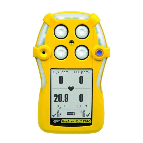
Page 22: Parts Of The Gasalertquattro
GasAlertQuattro Parts of the GasAlertQuattro Parts of the GasAlertQuattro Figure 1. Parts of the GasAlertQuattro Table 4. Parts of the GasAlertQuattro Item Description Item Description Item Description Item Description Liquid crystal display IntelliFlash (green LED) Button Alligator clip (LCD) Visual alarm indicator (red Combustible (LEL) sensor Audio alarm Battery pack... -
Page 23: Screen Elements
GasAlertQuattro User Manual Screen Elements... - Page 24 GasAlertQuattro User Manual Table 5. Button Button Description • To activate the detector, press and hold C in a safe area that is free of hazardous gas and in an atmo- sphere of 20.9% oxygen. • To deactivate the detector, press and hold C during the powering off countdown. Release C when OFF displays.
-
Page 25: Activating/Deactivating The Detector
Battery Test If battery power is critically low upon startup, the detector displays the Product Identification and Firmware Revision following screens and then deactivates. 2. The following two screens display showing the BW and product identification, and the firmware revision. -
Page 26: Startup Message
GasAlertQuattro User Manual Startup Message Alarm Setpoints 3. If data is entered in the Startup Message field in Fleet Manager 4. The alarm setpoints defined in Fleet Manager II display on the II, a startup message (50 characters maximum) displays on the detector in the following order: LCD. -
Page 27: Sensor Self Test
OFF then displays and the detector deactivates. For all sensor and self- test error screens, refer to Startup Troubleshooting. BW Technologies by Honeywell recommends that the sensor be replaced immediately. Refer to Replacing the Sensors. -
Page 28: Auto Zero Sensors
Warning displays. indicates which sensor failed and that a previous BW Technologies by Honeywell recommends that the auto-zero result for that sensor will be used to zero the sensor. sensors be calibrated regularly and at least once every 180 days (6 months). -
Page 29: Sensors Due For Calibration
Procedures, or press C and release to deactivate the detector. bration is disabled, the detector enters normal operation. Note BW Technologies by Honeywell recommends that the sensors be calibrated at least once every 180 days (6 months). Bump Test Due... -
Page 30: Sensors Due For Bump Test
Interval. Note a Caution BW Technologies by Honeywell recommends to bump test the BW recommends to bump test the sensors before each sensors before each day’s use to confirm their ability to day’s use to confirm their ability to respond to gas by... -
Page 31: Startup Self-Test Summary
• calculating the short-term exposure level (STEL), and displays for Hardware, Battery, Sensors, Clock, or Mem- • calculating the time-weighted average (TWA) exposures. ory contact BW Technologies by Honeywell. If an displays Auto-Zero, the detector uses the pervious zero readings. The detector can be zeroed in a safe area free of hazardous gas. -
Page 32: Installing Fleet Manager Ii
GasAlertQuattro User Manual Installing Fleet Manager II Fleet Manager II is required to configure the detector. To install Fleet Manager II, refer to the Fleet Manager II CD-ROM that includes the • installation wizard, and • Fleet Manager II Quick Reference Guide (located under Help). In Fleet Manager II there are two sections to add data, enable/disable features, and to define settings for the sensors and the detector: •... -
Page 33: Device Configuration
GasAlertQuattro Device Configuration Device Configuration 1. Activate the detector and wait for the startup sequence to complete. The Device Configuration section displays data about the detector, 2. Connect the USB cable to the USB port on the computer. allows for a startup message to be entered, and defines and enables/dis- ables settings for the detector. -
Page 34: Serial Number Field
GasAlertQuattro User Manual Serial Number Field This field displays the serial number (e.g. QA109-001000) of the detector. Note The Serial Number, Firmware Version, and Hardware Version fields are read-only fields. Settings for these fields are factory defined. Firmware Version This field displays the current firmware version that displays on the detector LCD during the startup sequence. -
Page 35: Startup Message
GasAlertQuattro Device Configuration Startup Message To enter normal operation, the sensor must be operating correctly. Refer to Troubleshooting Replacing the Sensors. Enter text to display on the detector LCD during startup (50 characters maximum). Enter information such as employee name, plant, area, The detector is shipped with Lockout on Self-Test Error disabled. -
Page 36: Latching Alarms
GasAlertQuattro User Manual Force Calibration The detector is shipped with the Confidence/Compliance Beep option disabled. Calibration is performed to adjust the sensitivity levels of the sensors to ensure accurate responses to gas. Latching Alarms If enabled and a sensor(s) is past due for calibration, the following If enabled, during an alarm condition the Latching Alarms option screen displays during the startup self-tests. -
Page 37: Force Bump
Device Configuration Force Bump Note BW recommends to bump test the sensors before each day’s use A bump test should be performed regularly to ensure the sensor(s) to confirm their ability to respond to gas by exposing the detector to are responding correctly to gas. -
Page 38: Cal Ir Lock
GasAlertQuattro User Manual Cal IR Lock Flip Display If enabled, the sensor(s) can only be calibrated using an IR device The detector can display screens at 0° (upright) or 180° (upside down), (IR Link or the MicroDock II station). depending upon how the detector is worn by the worker. If the Flip Display option is enabled, the LCD is viewed at 180°... -
Page 39: Stealth
GasAlertQuattro Device Configuration Stealth Datalog Interval When the Stealth option is enabled, the following features are disabled: The Datalog Interval (seconds) field defines how often the detector records a datalog (every 1-120 seconds). Enter the desired value. • backlight, The total number of 8-hour days datalogs that can be recorded is assum- •... -
Page 40: Intelliflash Interval
GasAlertQuattro User Manual Language IntelliFlash Interval The Language field provides a drop down menu that includes the The IntelliFlash Interval (seconds) field defines how often (every 1-120 following language options: seconds) the IntelliFlash occurs. Enter the desired value. • English The detector is shipped with the default setting of 1 second for the IntelliFlash Interval option. -
Page 41: Sensor Configuration
GasAlertQuattro Sensor Configuration Sensor Configuration The Sensor Configuration tab defines settings for each individual sensor. A separate sensor tab is provided for each sensor. Figure 6. shows the available option settings for the CO sensor. Note Depending upon the sensor, the options may vary. Figure 6. -
Page 42: Calibration Gas (Ppm)
GasAlertQuattro User Manual To disable a sensor, complete the following: 5. The LCD automatically updates. In the following example, the CO gas type and sensor readings no longer display. 1. Click Retrieve from Device to populate the fields with the current detector settings. 2. -
Page 43: Calibration Interval
Note alarm setpoints. BW recommends to bump test the sensors before each day’s use 2. Enter the TWA alarm setpoint for the H S and CO sensor in the to confirm their ability to respond to gas by exposing the detector to... -
Page 44: Stel Alarm
GasAlertQuattro User Manual Correction Factor (LEL) 3. Enter a value (4-16 hours) in the TWA Period (hours) field to define the duration of the moving average. For more informa- The Correction Factor option defines compensation factors for hydro- tion, refer to TWA Period (hours). -
Page 45: Twa Period (Hours)
GasAlertQuattro Sensor Configuration TWA Period (hours) 50% LEL = (%CH4) The TWA Period (hours) option calculates a time-weighted moving A percentage value can be entered in the 50% LEL = (%CH4) field average of accumulated gases over a period of 4-16 hours, to ensure to display the LEL reading in %vol. -
Page 46: 10% Lel (Of Reading) Over-Span
GasAlertQuattro Sensor Configuration 20.8 Base Reading If LEL by Volume CH4 is enabled, a percentage value must be entered in the 50% LEL = (%CH4) field. Refer to 50% LEL = (%CH4) If the 20.8 Base Reading option is enabled, the detector assumes (applicable to LEL sensor only). -
Page 47: Alarms
GasAlertQuattro User Manual Alarms Table 7. describes the detector alarms and corresponding screens. During an alarm condition, the detector activates the backlight, audible/visual/vibrator alarms (only vibrator when Stealth is enabled) and displays the current ambient gas reading. If more than one type or level of alarm exists simultaneously, a multi-gas alarm results. To change the factory-defined alarm setpoints, refer to Alarm, High... - Page 48 GasAlertQuattro Alarms Table 7. Alarms Alarm Screen Alarm Screen Multi-Gas Alarm Over Limit (OL) Alarm • Alternating low and high alarm siren • Fast siren (downward tone) and flash • Fast flash • Black box around gas flashes • Black box around gas flashes •...
- Page 49 GasAlertQuattro Alarms Table 7. Alarms Alarm Screen Alarm Screen Heartbeat Normal Deactivation • Sequence of alternating beeps and flashes • pulses every second to verify detector is operating correctly. • Vibrator alarm activates • Countdown initiates • OFF displays IntelliFlash Sensor Failure Alarm •...
- Page 50 GasAlertQuattro User Manual Alarm Screen Alarm Screen Note: If Low Alarm Acknowledge is enabled, the audible alarm can be dis- Confidence/Compliance Beep abled during a low alarm condition. The visual, audible, and vibrate alarms • One beep every 1-120 seconds (beep remain active until the alarm condition changes or the detector deactivates.
-
Page 51: Stopping A Gas Alarm
GasAlertQuattro Computed Gas Exposures Computed Gas Exposures Stopping a Gas Alarm a Warning The low and high alarms stop when the ambient gas concentration returns to the acceptable range. To prevent possible personal injury, do not deactivate the detector during a work shift. TWA, STEL, and peak Note readings reset when the detector is deactivated. -
Page 52: Viewing And Clearing Gas Exposures
GasAlertQuattro User Manual Viewing and Clearing Gas Exposures 3. Next, the TWA, and STEL gas exposures display. To view the TWA, STEL, and peak readings, press C twice rapidly. 1. The LCD first displays the • current time and date, •... - Page 53 GasAlertQuattro Computed Gas Exposures Press and release C to return to normal operation or press and Cancel Resetting Peak Readings: If C is pressed and released or C hold C to resent peak readings. is not pressed when the Hold C button to reset peaks screen displays, the following screen displays.
-
Page 54: Gas Alarm Setpoints
GasAlertQuattro User Manual Gas Alarm Setpoints Sample Gas Alarm Setpoints Gas alarms are activated when detected gas concentrations are above Table 10. lists alarm setpoints as defined by the US Occupational Safety or below the user-defined setpoints. The gas alarms are described in and Health Association (OSHA). -
Page 55: Bump Test
Caution force the detector into alarm. A bump test should be performed regularly BW recommends to bump test the sensors before each day’s use to confirm the sensors are responding correctly to gas, and that the to confirm their ability to respond to gas by exposing the sensors audible, visual, and vibrator alarms activate during an alarm condition. -
Page 56: Bump Test Installation
GasAlertQuattro User Manual To perform a manual bump test, refer to Table 11., Figure Figure and the following steps 1-6. Follow this procedure when Force Bump is enabled and a bump test is required during startup. Table 11. Bump Test Installation Item Description Gas cylinder and regulator... -
Page 57: Tightening The Calibration Cap
GasAlertQuattro Bump Test 1. Connect the calibration hose to the 0.5l/min regulator on 4. Apply gas. Verify the visual, audible, and vibrator alarms the gas cylinder. activate. 5. Close the regulator and remove the calibration cap from the Note detector. The detector will temporarily remain in alarm until Only use the calibration cap for bump tests and calibrations. -
Page 58: Calibration
BW recommends using premium grade calibration gases Used sensor: 60 seconds / new sensor: 5 minutes and cylinders that are certified to National Standards to ensure accurate calibration. -
Page 59: Connecting The Gas Cylinder To The Detector
GasAlertQuattro Calibration Connecting the Gas Cylinder to the Detector Refer to Figure 10., Figure 11., and the following procedures to connect the gas cylinder to the detector for calibration. Read steps 1-6 before starting calibration. 1. Verify the calibration gas being used matches the span concentration value(s) that are set for the detector. -
Page 60: Calibration Procedures
GasAlertQuattro User Manual Calibration Procedures 4. Connect the calibration hose to the regulator on the gas cylin- der. The calibration procedure is written as the procedure is intended. If an 5. Refer to Calibration Procedures to begin calibration. error or alarm screen displays, refer to Calibration Troubleshooting. - Page 61 GasAlertQuattro Calibration 3. Press and hold C as the detector performs the Powering Off 5. The detector then performs the calibration countdown. Con- countdown. tinue holding C when the Starting Calibration screen dis- plays. Important! 6. If Cal IR Lock is enabled, an IR device (IR Link or MicroDock II Continue holding C until the Calibration started screen station) must be used to continue calibration.
-
Page 62: Zero Sensor
GasAlertQuattro User Manual Apply Calibration Gas 7. Release C when Calibration Started displays. 9. When the following screen displays, attach the calibration cap. Refer to Figure 12. If a sensor is not due yet for calibration, its box will have a greyed-out checkmark. If zeroing sensors, press C to abort calibration to return to nor- mal operation. - Page 63 GasAlertQuattro Calibration Attach the calibration cap to the detector (Figure 12.). Turn the 12. The detector then begins calibrating the sensors. calibration cap knob firmly to ensure a tight seal to the detector. Note Ensure the knob is securely fastened before applying gas. Do not overtighten the calibration cap.
-
Page 64: Days To Next Calibration
GasAlertQuattro User Manual Days to Next Calibration 14. When calibration is complete, the following screen displays. Note If a sensor fails calibration, the next calibration due date for that sensor will not reset. Refer to Calibration Troubleshooting. 15. All successfully calibrated sensors automatically reset to the number of days defined in the Cal Interval field in Fleet Man- ager II. -
Page 65: Calibrating Using An Ir Device
GasAlertQuattro Calibration Calibrating Using an IR Device If the Cal IR Lock option is enabled, the sensors must be calibrated 5. From the Devices toolbar, click . The Device using one of the following IR devices: Selection popup displays. • IR Link With Fleet Manager II •... -
Page 66: Calibrate Device Dialog Box
GasAlertQuattro User Manual The Calibrate Device dialog box displays. 10. Click inside the checkbox for each sensor that will be calibrated, and then click . The following screen displays. Figure 15. Calibrate Device Dialog Box 11. Return to Zero Sensor step #8 in the Calibration Procedures 9. -
Page 67: Event Logs
GasAlertQuattro Event Logs Event Logs Datalogs The detector records the 30 most recent gas alarm events. Information The detector records datalog samples that can be compiled to create a that is recorded from an event is as follows: report using Fleet Manager II. From Fleet Manager II, define how often the detector records a datalog sample (1-120 seconds) in the Datalog •... -
Page 68: Bump And Calibration Results
GasAlertQuattro User Manual Bump and Calibration Results • Battery status • Configuration changes The detector records the MicroDock II bump test and calibration results. The results can then be imported into Fleet Manager II to create detailed • Low and high alarm setpoints (all sensors) reports. -
Page 69: Downloading Datalogs And Event Logs
GasAlertQuattro Bump and Calibration Results Downloading Datalogs and Event Logs • Last bump test performed • Next bump test due date The datalog and event log files can only be downloaded to a PC using the IR Link or the MicroDock II base station. Refer to one •... -
Page 70: Software Requirements
Refer to Charging the Rechargeable Bat- tery. • Use only BW recommended alkaline batteries. Refer to Specifications. • Charge the battery in a safe area that is free of hazardous gas in temperatures ranging from of 32°F to 104°F (0°C to 40°C). -
Page 71: Charging The Rechargeable Battery
GasAlertQuattro Maintenance Charging the Rechargeable Battery • Charge the battery using BW charger adapters designed for the GasAlertQuattro only. Do not use any other charger adapt- ers. Failure to adhere to this caution can lead to fire and/or explosion. • The charging adapter is voltage specific to your region. Use of the charging adapter outside your region will damage the charger and the detector. - Page 72 GasAlertQuattro User Manual Table 13. Connecting the Charger Adapter 4. The lithium battery may require 6 hours to reach full capacity. While charging, the LCD displays the battery icon. Item Description Detector IR and charger interface Charger adapter Charger cable a Warning The battery must be charged in a safe area that is When the battery is fully charged, the following screen...
-
Page 73: Optimum Battery Operation
GasAlertQuattro Maintenance Optimum Battery Operation Replacing the Battery Pack To ensure maximum use of the battery, perform the following: Battery Pack Retaining Screw • To obtain full operating capacity, allow the battery to fully charge The retaining screw provided with the detector must be used to lock the and discharge three times. -
Page 74: Replacing The Alkaline Batteries
Replacing the Alkaline Batteries a Warning To avoid personal injury and/or damage to the detector, use only BW recommended alkaline batteries. Refer to Specifications. Change the alkaline batteries only in safe area that is free of hazardous gas. To replace the alkaline batteries, refer to Figure 19.,... -
Page 75: Ejector Bar Unhooked From Release Clasp
GasAlertQuattro Maintenance 3. Remove the alkaline battery pack. Refer to Replacing the Bat- 5. Using the tab, pull on the ejector bar. tery Pack. 4. Unhook the ejector bar from the release clasp. Move the ejec- tor bar towards the top of the battery pack until it is aligned hor- izontally over the batteries. -
Page 76: Pulling Up On The Ejector Bar
GasAlertQuattro Maintenance 6. To the left of the tab, pull up on the ejector bar. 9. Insert the new batteries. Position the positive end of the battery at a 30° angle and insert into the battery pack before pushing the negative end down into place. Refer to Figure 22. -
Page 77: Replacing The Sensors
GasAlertQuattro Maintenance Replacing the Sensors 1. Press and hold C to deactivate the detector. 2. Press the release latch and remove the battery pack. a Warning 3. Remove the six machine screws from the rear shell. To avoid personal injury and/or property damage, use only sensors that are specifically designed for the 4. -
Page 78: Replacing A Sensor Or Sensor Filter
GasAlertQuattro Maintenance Figure 23. Replacing a Sensor or Sensor Filter... -
Page 79: Replacing The Sensor Filter
GasAlertQuattro User Manual Replacing the Sensor Filter 3. Remove the six machine screws from the rear shell. 4. Remove the front shell. To replace the sensor filter, refer to Figure 24., Figure 25. and the following steps 1-9. 5. Remove the sensor filter. 6. -
Page 80: Troubleshooting
The detector does not activate. Charge the rechargeable battery pack. Refer to Charging the Rechargeable Battery. Damaged detector. Contact BW Technologies by Honeywell. Replace alkaline batteries. Refer to Replacing the Alkaline Batteries. Automatic deactivation due to critical low battery. Charge the rechargeable battery pack. Refer to... - Page 81 20.9% oxygen. A new sensor has been inserted Calibrate the sensor. General fault. Contact BW Technologies by Honeywell. The activation startup self-test fails. Refer to Startup Troubleshooting. If required, refer to Sensor error. Replacing the Sensors.
- Page 82 GasAlertQuattro Troubleshooting Table 14. Troubleshooting Problem Possible Cause Solution Detector Operation Used sensor: Wait 60 seconds Sensors not stabilized. New sensor: Wait 5 minutes Detector does not display normal Sensor(s) requires calibration. Refer to Calibration Procedures. gas reading after startup sequence. Detector is operating properly.
- Page 83 GasAlertQuattro User Manual Table 14. Troubleshooting Problem Possible Cause Solution Refer to Sample Gas Alarm Setpoints. Define the alarm set- Alarm setpoint(s) are set incorrectly. points in Fleet Manager II. Detector does not enter alarm. Refer to Sample Gas Alarm Setpoints.
- Page 84 Charge the battery for 8 hours. If the battery indicator does Battery indicator does not display Battery is depleted below normal levels not light after charging, contact BW Technologies by Hon- when charging. eywell.
-
Page 85: Startup Troubleshooting
GasAlertQuattro User Manual Startup Troubleshooting Table 15. Startup Troubleshooting Error Screen Problem Solution Error Screen Problem Solution Auto-zero Error Calibrate the sensor. Last Calibration Press C and calibrate the Failed sensor(s) immediately. Refer Sensor(s) failed to Calibration Procedures. auto-zero Displays when the last If Cal IR Lock is enabled, an calibration failed. - Page 86 Caution or use the MicroDock II If the Force Bump station, otherwise press BW Technologies by Honeywell recommends to bump Test option is C to deactivate the test the sensors before each day’s use to confirm their enabled, the sensors detector.
-
Page 87: Calibration Troubleshooting
Dock II User Manual Self-test Fail Replace the sensor or con- Calibration Error Verify the span gas values on BW Technologies by the cylinder match the span tact If a sensor(s) fails Insufficient amount Honeywell gas values set for the detector. -
Page 88: Replacement Parts And Accessories
GasAlertQuattro User Manual Replacement Parts and Accessories Model No. Description a Warning Gas Cylinders and Kits To avoid personal injury or damage to the detector, use only the specified replacement parts. Quad gas cylinder: CH -2.5%, O -18.0%, CG-Q58-4 S-25 ppm, CO-100 ppm, bal. N (58 l) To order parts or accessories listed in the following table, contact Technologies by... - Page 89 GasAlertQuattro Replacement Parts and Accessories Model No. Description Model No. Description Chargers and Power Options GA-LY-1 Short strap 6 in. (15.2 cm) GA-PA-1-MC5 GasAlertQuattro multi-unit power adapter GA-ES-1 Extension strap 4 ft. (1.2 m) QT-C01-MC5 GasAlertQuattro multi-unit cradle charger GA-ARM-1 Arm band GA-VPA-1 Vehicle power adapter...
-
Page 90: Specifications
Capillary controlled concentration sensor Calibration: Zero and automatic span Bump test specified limits: BW recommends using a gas cylinder that User options: Startup message, lockout on sensor error, safe mode, will ensure the combustible sensor has an accuracy of -0 to +20% of IntelliFlash, confidence/compliance beep, latching alarms, force calibra- actual reading (reference CAN/CSA C22.2 No. - Page 91 GasAlertQuattro Specifications Sensor options: Sensor enable/disable, calibration gas values, calibra- First-time charge: 6 hours tion interval, bump test interval, alarm setpoints (low/high/TWA/STEL), Normal charge: 6 hours STEL interval, TWA period, TWA method, auto zero during startup Warranty: 2 years including sensors enable/disable, LEL correction factor, 10% (of reading) over-span, low alarm acknowledge, O measurement, LEL gas measurement, and %...
-
Page 92: General Datalog Specifications
GasAlertQuattro User Manual General Datalog Specifications This equipment has been tested and found to comply with the limits for a Class B digital device, pursuant to Part 15 of the FCC Rules and Storage: 360 hours at 15-second intervals ICES-003 Canadian EMI requirements. These limits are designed to Memory type: Wraparound memory ensures most recent data is always provide reasonable protection against harmful interference in a residen- saved... - Page 93 127908 EN-B ©2017 BW Technologies by Honeywell. All rights reserved.
Need help?
Do you have a question about the GasAlert Quattro and is the answer not in the manual?
Questions and answers