Table of Contents
Advertisement
Quick Links
Advertisement
Table of Contents

Summary of Contents for BAQ dynaROCK II
- Page 1 II Manual Version 1.3...
-
Page 3: Table Of Contents
Table of contents 1 Introduction.....................6 1.1 Main applications and measuring range..........7 1.1.1 Main applications................7 1.1.2 Measuring range................7 1.2 Scope of delivery...................8 1.3 Operating conditions................8 2 Manual......................9 2.1 Lettering....................9 2.2 Text boxes....................9 3 Equipment description and measurement process........10 3.1 Impact device type D................10 3.1.1 Special impact device types............10 3.2 Leeb hardness measurement process..........12 4 General notes on the operation..............13... - Page 4 8.2 Continue measurement in existing series..........27 8.3 Deleting a series..................27 8.4 Displaying a series................27 8.5 Data transfer..................27 8.5.1 Installation...................28 8.5.2 Connection to dynaROCK II............28 8.5.3 Transfer of dynaROCK II series of measurements.....29 8.5.4 Transfer of readings..............30 9 System settings....................30 9.1 Language.....................30 9.2 Time.....................30 9.3 Date.....................30 9.4 Configuration..................31...
- Page 5 13.4 Español....................36 14 Technical data.....................37 15 Appendix.....................38 Appendix 2: License information..............43...
-
Page 6: Introduction
HS or tensile strength (MPA; measurable only with the impact device types D, DC and G). A limit-value acoustic alarm facilitates the evaluation. The dynaROCK II is provided with a measured value memory in which up to 500,000 measured values, with date, time and measuring parameters, can be stored. -
Page 7: Main Applications And Measuring Range
INTRODUCTION 1.1 Main applications and measuring range 1.1.1 Main applications • Heavy workpieces • Cast parts • Damage analysis on pressure vessels, steam turbo-generators and other systems • Bearings and other parts • Fixed-assembled machines and immovable component parts • Surfaces of small hollow spaces •... -
Page 8: Scope Of Delivery
INTRODUCTION 1.2 Scope of delivery Article Number Remark Standard 1 Basic device scope 2 Impact device type D Including cables delivery 3 Hardness comparison block 4 Cleaning brush 5 Manual 6 Case 7 Interface cable 8 USB charging adapter Optional 9 Different special impact See Chapter 3 and accessories... -
Page 9: Manual
MANUAL 2 Manual 2.1 Lettering Operating elements Operating elements Keys Standard text Descriptions and explanations in text form Important notes Important notes and remarks 2.2 Text boxes Explanations functions operating Operating elements elements are framed in blue. Green fields describe user inputs Entry fields... -
Page 10: Equipment Description And Measurement Process
EQUIPMENT DESCRIPTION AND MEASUREMENT PROCESS 3 Equipment description measurement process 3.1 Impact device type D 1 - Release button 2 - Bolt-arming sleeve 3 - Guide pipe 4 - Reactance coil part 5 - Placement ring 6 - Impact body 7 - Connection cable 3.1.1 Special impact device types The technical specifications of the individual impact devices are indicated in... - Page 11 EQUIPMENT DESCRIPTION AND MEASUREMENT PROCESS Type D : Standard impact device for most hardness testing tasks Type DC : Extremely short impact device for measurements at inaccessible locations or in pipes Type C : Impact device with lower impact energy e.g. for measurements on surface-hardened parts.
-
Page 12: Leeb Hardness Measurement Process
EQUIPMENT DESCRIPTION AND MEASUREMENT PROCESS 3.2 Leeb hardness measurement process The measurement process employed here exploits the difference between the impact and rebound speed of a small impact body. This is fired in the impact device onto the sample surface with an exactly defined energy. The plastic deformation on generating the impression on the sample surface requires energy. -
Page 13: General Notes On The Operation
GENERAL NOTES ON THE OPERATION 4 General notes on the operation 4.1 Keys Switching on/off the device. Changes the impact direction Changes the hardness scale. Changes the material. Delete last measurement point Display statistics Into the main menu Cursor keys With these keys, menu items are selected and the re- quired values in fields set-adjusted. -
Page 14: Status Indicator Line
GENERAL NOTES ON THE OPERATION 4.2 Status indicator line The rechargeable battery status and the time are displayed in the status indicator line above in the window. 4.3 The menus A menu consists of a list of available menu items and a bar which identifies the already active menu item. - Page 15 GENERAL NOTES ON THE OPERATION Below the characters is located a strip with command buttons for control. These command buttons are allocated as follows: Switching between upper case and lower case Accepting text and closing text entry windows Cancel Closing text entry windows without accepting the text The field on which the focus is placed is identified by a yellow background.
-
Page 16: The Number Field
GENERAL NOTES ON THE OPERATION 4.5 The number field A number field is used for the input of numbers. It consists of mostly several digits which can be changed separately, and a marker, as well as the cursor which can be displaced with the cursor keys ◄ and ► within the number field. The Item on which the cursor is at this time can be modified through pressing the cursor keys ▲... - Page 17 IMPLEMENTATION OF A MEASUREMENT – The sample must be placed onto the underlay so that it is stable and flush • In case of measurements on large plates, long rods or curved work pieces, the impact effect of the impact device can cause small deformations or vibrations which lead to measuring errors, also when the weight of the sample corresponds to the specifications in 5 (on Page 41in the appendix).
-
Page 18: Measuring Parameter Settings
Note: The hardness of the comparison block is indicated on the block. Hardness comparison blocks with DKD certificate are available in three different hardnesses. When the measured values of the dynaROCK II deviates from the hardness of the comparison block, the device must be calibrated. 5.2.1 Operational startup •... -
Page 19: Mounting The Impact Device
IMPLEMENTATION OF A MEASUREMENT 5.2.3 Mounting the impact device Press the placement ring of the impact device firmly and without wobbling onto the test specimen. The impact direction must correspond to the set-adjusted direction. 5.2.4 Measuring Press release button above on the impact device. Sample and impact device must be held steady and stable in this case. -
Page 20: Operation Of The Device
IMPLEMENTATION OF A MEASUREMENT The measurement is completed with the acoustic signal. If the Leeb hardness is to be converted into another hardness scale, a benchmark comparison test must be carried out in order to obtain a suitable conversion factor for the corresponding material. Test measurements are carried out on the same sample with a well calibrated Leeb hardness testing device, and with another hardness tester, according to the required hardness scale. -
Page 21: Description Of The Measurement Window
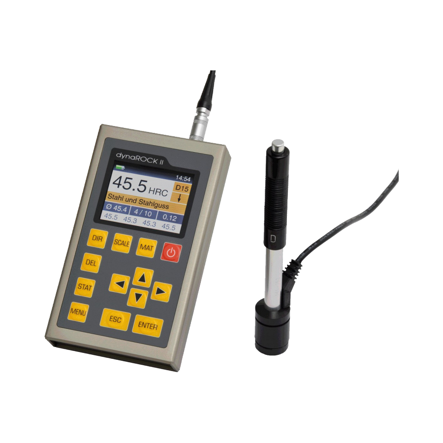
OPERATION OF THE DEVICE Illustration 4: Measurement window 6.2.1 Description of the measurement window Charge status Displays the residual charge of the batteries. display: Time: Current time Measured value: Current measured value Hardness scale: Current hardness scale Material: Current material Impact device type: Type of the connected impact device Impact direction:... -
Page 22: Key Layout Of The Measurement Window
OPERATION OF THE DEVICE place, Vickers, Brinell, Shore and tensile strength without any decimal place. If the measured value lies within the tolerance limits, a beep is emitted, otherwise 2 short tones. 6.2.3 Key layout of the measurement window Changes the impact direction SCALE Changes the hardness scale. -
Page 23: Display Of The Statistics
OPERATION OF THE DEVICE 6.3.1 Display of the statistics The output of the statistical evaluation is implemented as soon as the number of measurements set-adjusted in the measuring parameters have been made, or the key STAT is pressed. First to be outputted are average value, standard deviation, relative standard deviation Illustration 5: Statistics (standard deviation in % of the average value),... -
Page 24: Measuring Parameter
MEASURING PARAMETER 7 Measuring parameter 7.1 Description After switching on the dynaROCK II, the last employed combination of measuring parameters is always active. The measuring parameters in detail: I m p a c t d i r e c t i o n : The impact direction is set-adjusted with the aid of the key DIR in the measurement window. -
Page 25: Administration Of The Measuring Parameter Sets
The number of values which should be used for the statistical evaluation In the dynaROCK II combinations of measuring parameters can be stored under a user-defined name. In this way, the measuring parameters required for specific applications can be called up easily. -
Page 26: Loading Measuring Parameters
With the cursor keys, the required item is selected from the list of the existing measuring parameter data records and deleted with ENTER. 8 Memory functions In the dynaROCK II, a total of up to approx. 500,000 measured values can be stored. These measured values are organized in series of measurements (series). -
Page 27: New Series
8.5 Data transfer The saved series of measurements can be transferred to the PC by means of the transfer program supplied with the dynaROCK II. For that, the dynaROCK II has to be connected to the PC via USB. The... -
Page 28: Installation
After the connection has been established, the names of the series of measurements saved in the dynaROCK II will be read and displayed in the list 'dynaROCK II measurement series'. The active measurement parameter will also be read and displayed. -
Page 29: Transfer Of Dynarock Ii Series Of Measurements
8.5.3 Transfer of dynaROCK II series of measurements Select the series of measurements that should be transferred to the PC from the list of 'dynaROCK II measurement series'. Then press 'Transfer series'. Next you have to select the folder on the PC, where the transferred data should be stored. -
Page 30: Transfer Of Readings
The data can be saved to the PC in the same format as mentioned above. During the measurement, it is not possible to transfer a dynaROCK II series or to disconnect the dynaROCK II. The measurement has to be stopped to do this. -
Page 31: Configuration
SYSTEM SETTINGS 9.4 Configuration 9.4.1 Date format Under the menu item System / Configuration / Date format , the format in which the date is entered and displayed can be set-adjusted. Meaning of the alphabetic characters of the format specification: Month YYYY: Year 9.4.2 Key SCALE... -
Page 32: Query Whether Series Should Be Saved
USB flash drive. For transferring the calibration to the dynaROCK II the flash drive has to be plugged in and the menu item System / Impact device calibration has to be selected. -
Page 33: Factory Defaults
SYSTEM SETTINGS 9.6 Factory defaults With the aid of the menu item System / Factory defaults , the current measuring parameters and the date format can be reset to the default values. 9.7 System information Under the menu item System / Info , the system information is displayed. -
Page 34: Safeguarding And Transport
CARE AND MAINTENANCE technical service. Replacement services cannot be made in case of repairs carried out by yourself. 12 Safeguarding and transport The test device should be kept at room temperature and protected against vibrations, strong magnetic fields, corrosive materials, moisture and dust. The original packing should be used for the transport of the device. -
Page 35: Information On Waste Disposal
INFORMATION ON WASTE DISPOSAL 13 Information on waste disposal Verbraucher sind gesetzlich verpflichtet Altbatterien zu einer geeigneten Sammelstelle/Verkaufsstelle/Versandlager bringen. Die durchgestrichene Mülltonne bedeutet: Batterien und Akkus dürfen nicht in den Hausmüll. Pb, Cd und Hg bezeichnet Inhaltsstoffe die oberhalb der gesetzlichen Werte liegen. 13.1 English Consumers are legally required to dispose of batteries at suitable collection points, vending points or dispatch bays. -
Page 36: Español
INFORMATION ON WASTE DISPOSAL 13.3 Italiano 13.4 Español Los usuarios están obligados por ley a depositar las pilas viejas en un punto de recogida adecuado /punto de venta/centro de envío. El contenedor de basura tachado significa: la pilas no deben desecharse en la basura doméstica. -
Page 37: Technical Data
14 Technical data Measurement range 170 HLD to 960 HLD Impact direction 360° Hardness scale HL, HB, HRB, HRC, HV, HS and tensile strength Statistics average value, minimum, maximum, standard deviation. Outliers can be deleted. Display LCD 320x240 pixels, 65536 colors Data memory 500,000 data records with date, time and GOOD/BAD rating and impact direction... -
Page 38: Appendix
TECHNICAL DATA Impact Hardness of the Leeb Fault of the device hardness comparison measured Repeatability type block value 760 ±30 HLD ±6 HLD 6 HLD 530 ±40 HLD ±10 HLD 10 HLD 760 ±30 HLDC ±6 HLDC 6 HLD 530 ±40 HLDC ±6 HLDC 10HLD 878 ±30 HLDL... - Page 39 APPENDIX 15 Appendix Material Hardness Impact device scale D / DC D+15 20,0 – 68,4 20,0 – 68,4 20,0 – 68,4 20,0 – 68,4 38,4 – 99,5 38,4 – 99,5 38,4 – 99,5 47,7 – 99,9 38,4 – 99,5 81 – 654 81 –...
- Page 40 APPENDIX Bronze 60 – 290 (copper- aluminum / copper-tin alloys) Wrought 45 – 315 copper alloys Table 3 Impact device type DC/D/DL D+15 Impact energy 11 mJ 11 mJ 2.7 mJ 90 mJ Weight of the impact 5.5 g /DL: 7.2 g 7.8 g 3.0 g 20.0 g...
- Page 41 APPENDIX Impact device type DC/D/DL D+15 Surface Roughness Ra / Rt 2 µm/10 µm 2 µm/10 µm 0.4 µm / 2.5 7 µm / 30 µm ISO Class µm N5 Minimum weight of the sample For direct > 5 kg >...
- Page 42 APPENDIX Type Sketch of the placement Remarks ring For convex surfaces Z10-15 R10 – R15 For convex surfaces Z14.5-30 R14.5 – R30 For convex surfaces Z25-50 R25 – R50 For concave surfaces HZ11-13 R11 – R13 For concave surfaces HZ12.5-17 R12.5 –...
-
Page 43: Appendix 2: License Information
License (GPL) or under the GNU Lesser General Public License (LGPL). The free software source code can at least for a period of 3 years be requested from BAQ GmbH. However, please be noted that we cannot provide guarantee with the source code, and there is also no technical support for the source code from us. - Page 44 APPENDIX 2: LICENSE INFORMATION CONSEQUENTIAL DAMAGES (INCLUDING, BUT NOT LIMITED TO, PROCUREMENT OF SUBSTITUTE GOODS OR SERVICES; LOSS OF USE, DATA, OR PROFITS; OR BUSINESS INTERRUPTION) HOWEVER CAUSED AND ON ANY THEORY OF LIABILITY, WHETHER IN CONTRACT, STRICT LIABILITY, OR TORT (INCLUDING NEGLIGENCE OR OTHERWISE) ARISING IN ANY WAY OUT OF THE USE OF THIS SOFTWARE, EVEN IF ADVISED OF THE POSSIBILITY OF SUCH DAMAGE.
- Page 46 BAQ GmbH Hermann-Schichting-Straße 14 38110 Braunschweig Germany www.BAQ.de Tel.: +49 5307 95102-0 Fax: +49 5307 95102-20 email: baq@baq.de...
Need help?
Do you have a question about the dynaROCK II and is the answer not in the manual?
Questions and answers