Advertisement
Rowe BC100/BC150 Update Kit Installation Instructions
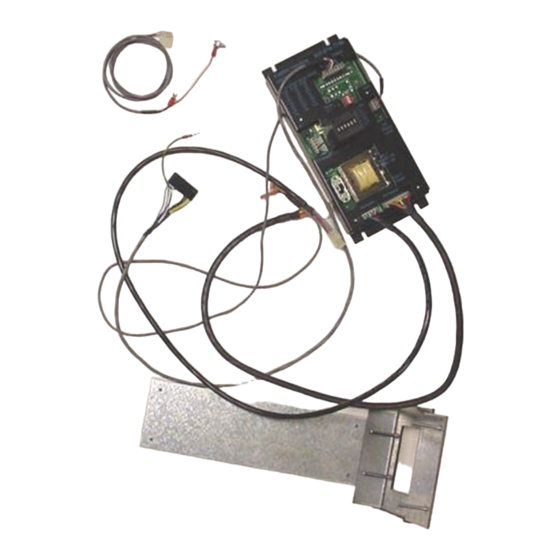
KIT CONTENTS
Control Board with yellow printing
Metal Slide Plate – short wide mouth
Wiring Harness – main power to P1 of board
Wiring Harness – to empty lamp on front door to P5 on left hand side of board = empty
Wiring Harness – to Coin Dispense Assembly to C2 of board
Wiring Harness – to Mars AE/VN validator to C4 of board; standard
PARTS KITS CONTENTS
4 8-/32 3/8" self threading screws
8 of 11-32 hex nuts
The following instructions are for installation of an upgrade board kit in a Rowe
BC100/BC150. Prior to installation be sure to confirm the hopper, hopper drive motor, coin
count sensor, and red LED count emitter are in working condition.
1. Remove the hopper from the changer.
2. Insert a $5.00 bill so the Coin Dispenser Assembly releases most of the coins held in
escrow.
3. Unplug the power cord from the wall outlet.
4. Remove the bill transport by sliding the transport forward until it "catches". Unplug the
connector from the right hand side, depress the release lever and slide the transport
forward out of the tracks.
5. Remove the bill box (4-50346-01) from the stacker assembly.
6. Remove the stacker assembly by unscrewing the two ¼" hex screws, it may be
necessary to hold the nuts under the assembly with a pair of pliers. Disconnect the
harness from the upper rear right hand side and pull the stacker assembly forward out
of the changer. Replace the two screws and nuts.
7. Remove the coin chute that channels the coins from the hopper to the coin cup. It is
held in place by two ¼" hex screws on the left hand side of the chute.
8. Remove the Power Control Center (65073501). Unscrew the two ¼" hex screws at the
very bottom of the changer cabinet. Begin sliding the power supply out of the changer
and twist it upright so the four wiring harness connectors are visible. Disconnect all four
of the wiring harness connectors and remove the Power Control Center.
9. Remove the Bill Changer Computer Control Center. Slide the board towards yourself.
When the board is about 60% out of the cabinet it should automatically "catch" on a
hook. Remove the four wiring harness connectors; there are three on the rear and one
on the bottom. Remove the green and yellow ground wire by unscrewing it from the
upper rear of the metal slide plate. The board can now be removed from the cabinet by
depressing the release latch that is attached to the side of the cabinet.
10. Unhook the harness at the bottom of the Coin Dispenser Assembly (6-50880-09).
Unscrew the 3/8" bolt at the top center of the assembly. Tilt the unit forward, and then
slide the assembly to the left so it is released from the side pivot hooks. Lift the
assembly up and out of the changer and place it in a work area.
11. The Coin Dispenser Assembly is converted to a direct payout system. The modification
of the assembly involves removing the two-bucket solenoids and permanently
positioning the internal coin diverting flaps. The electronics used to count the coins are
Advertisement
Table of Contents

Summary of Contents for Rowe BC100
- Page 1 8 of 11-32 hex nuts The following instructions are for installation of an upgrade board kit in a Rowe BC100/BC150. Prior to installation be sure to confirm the hopper, hopper drive motor, coin count sensor, and red LED count emitter are in working condition.
- Page 2 not changed. The upgrade kit does not hold any coins in escrow, so the metal escrow flaps connected to the bucket solenoids are removed. FLAP REMOVAL INSTRUCTIONS There are three black rods on the bucket assembly. Remove the e-clip on either side of the assembly from each of the two rods that have e-clips on the outside of the assembly.
- Page 3 Switch 4 “on” pays out 8 coins Installation Instructions for Hopper “Low Coins” Screw (Rowe BC1, SBC2/4 and BC100 Changers) Upon verifying the kit and changer are working properly, a low coins screw can be installed. The low coins screw is installed to prevent shortchanging a customer. If the changer is in an attended location and the hopper will not empty, it is not necessary to install the low coins screws.
- Page 4 Drill an 11/64” hole in the black plastic area at the bottom of the hopper. The hole should be located at the center of the hopper and 7/8” from the very bottom of the plastic. Positioning is important so that a coin does not get wedged between the screw and the hopper body.
- Page 5 OPERATIONAL OVERVIEW The hopper LED lights while the hopper is running The meter clicks once per dollar value at the end of the vend cycle Headers P1 and P2 are not used in this application; reserved for SBC2/SBC4. Dip Switch Settings AE2400 $1-$5 AE2600 $1-$20 VN2500 $1-$5...
- Page 6 Rowe BC 100 Figure 1 Figure 2 Figure 4 Figure 3 Figure 6 Figure 5...
Need help?
Do you have a question about the BC100 and is the answer not in the manual?
Questions and answers