Advertisement
Quick Links
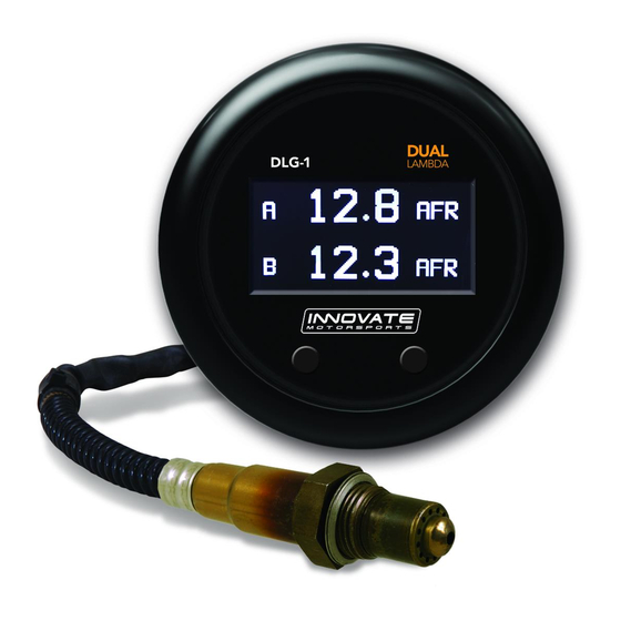
DLG-1
User Manual
Warning!
The Oxygen Sensor used in this device gets very hot in operation.
Do not touch a hot sensor. Do not let a hot sensor touch a combustible surface. Do not use the
sensor with or near flammable liquids or gases. Failure to heed these warnings may result in
severe burns, explosions, fires, or other dangerous events.
Advertisement

Summary of Contents for Innovate DLG-1
- Page 1 DLG-1 User Manual Warning! The Oxygen Sensor used in this device gets very hot in operation. Do not touch a hot sensor. Do not let a hot sensor touch a combustible surface. Do not use the sensor with or near flammable liquids or gases. Failure to heed these warnings may result in...
- Page 2 While on the main screen, press and HOLD both interface buttons to sync the second A/F channel connected to the serial IN port. Changing the DLG-1’s gauge face and/or bezel 1. Lay the DLG-1 face down and remove the three #2 phillips screws from the outside rim of the back plate.
- Page 3 3. Configure the gauge as desired by changing the gauge face and/or bezel. 4. Make sure every piece is positioned correctly using the locating tab and reassemble the gauge. 5. Reinstall the three #2 phillips screws verifying that the buttons are not binding on the gauge lens.
-
Page 4: Installation
See the next section for a relay installation diagram. On both the DLG-1 and LC-2, the BLACK wire should be grounded to a solid ground source. The best possible ground source would be the... - Page 5 DLG-1 and LC-2 to the ground or signal ground of the device you are interfacing with.
- Page 6 Relay Wiring Instructions DLG-1 Mounting and Routing The DLG-1 gauge fits in any standard 2 1/16” (52mm) gauge pod. Mounting of the gauge should be done in such a manner that the cables are not being forcefully pulled and strained from the gauge itself. Route the sensor and solenoid cables avoiding contact with the exhaust system and other vehicle components that could damage the cable.
- Page 7 Interfacing the DLG-1 with the LC-2 1. Verify that both the DLG-1 and LC-2 are powered OFF. 2. Both the DLG-1 and LC-2 have 4-pin Molex connectors labeled IN and OUT. Using P/N 3846 included in your kit, connect the OUT port of the LC-2 to the IN port of the DLG-1.
- Page 8 The calibration procedure requires that the oxygen sensors be in free air, this means removed from the exhaust system completely. The procedure below will allow both sensors (from the DLG-1 and LC-2) to be calibrated at the same time. 1. With the sensors disconnected, apply power to the DLG-1 and LC-2.
- Page 9 Leave unit powered on for a minimum of 30 seconds. 2. Power down the DLG-1 and LC-2 and attach the oxygen sensors using the cable provided. When making these connections, make sure they are fully seated and locked.
- Page 10 DLG-1 Configuration The DLG-1 can be setup to display AFR or Lambda. When configured to display AFR, it can be setup for any fuel type setting. The configuration can be done on the gauge itself by utilizing the interface buttons or by connecting the unit to the LM Programmer software.
- Page 11 Windows task bar. Once you have completed your desired changes, press the Program button on the lower right on the software application. You will know that the DLG-1 has been programmed successfully when the Program button grays out. Display Settings (Gauge Abbreviations) 1.
- Page 12 Windows task bar. 4.1.1 Programming Analog Output Connect the DLG-1 to the computer and launch LM Programmer. Select the Analog Output tab. The analog output configuration screen shows voltage versus Lambda for the analog output. The graph display is automatically scaled to the selected voltages values.
- Page 13 5. The software will now prompt you to confirm that you wish to overwrite the firmware currently on your DLG-1. 6. Click OK, the gauge of the DLG-1 will go blank. DO NOT power off or disconnect the DLG-1 from the computer until the firmware progress screen completely disappears.
- Page 14 Logging data from your DLG-1 with LogWorks 1. Connect the OUT port of the DLG-1 to the provided serial programming cable. Connect the other end of the serial programming cable to your computer. If your computer does not...
Need help?
Do you have a question about the DLG-1 and is the answer not in the manual?
Questions and answers