Table of Contents
Advertisement
Quick Links
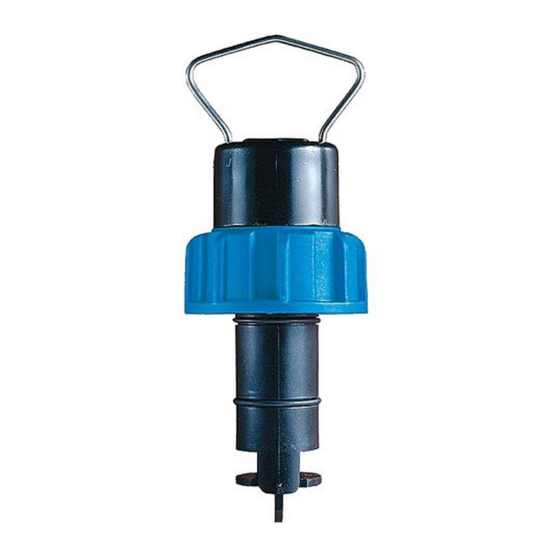
+ GF + SIGNET 2536/3-8512-XX Low Flow Sensor
3-2536.090-1
B-4/98
SAFETY INSTRUCTIONS
1. Do not remove from pressurized lines.
2. Do not exceed maximum temperature/pressure specifications.
3. Do not install/service without following installation instructions (see sensor manual).
4. Wear safety goggles and faceshield during installation/service.
5. Do not alter product construction.
6. Failure to follow safety instructions could result in severe personal injury!
1. Location of Fitting
Recommended sensor upstream/
downstream mounting requirements.
2. Sensor Mounting Position
• Horizontal pipe runs: Mount sensor in the upright (0°) position for best overall performance. Mount at a
maximum of 45° when air bubbles are present. Do not mount on the bottom of the pipe when sediments
are present.
• Vertical pipe runs: Sensor must be mounted in lines with UPWARD flow only.
3. Sensor Wiring
2536/3-8512-XX
Sensors
black (3.3 to 24 VDC)
red (signal out)
silver (DC return)
• Use 2-conductor shielded cable for cable extensions up to
300 m (1000 ft).
• Cable shield must be maintained through cable splice.
• + GF + SIGNET Intelek-Pro, use 2536 input card setting
• Refer to you instrument manual for specific wiring details.
4. + GF + SIGNET Fittings
Type
Description
Plastic tees
• 0.5 to 4 in. versions
• PVC or CPVC
• Mounts via glue-on fittings
PVC glue-on
• 2 to 4 in., cut 1-7/16 in. hole in pipe
saddles
• 6 to 8 in., cut 2-1/4 in. hole in pipe
(O-ring not
• Align wedge arrows with saddle arrows during assembly.
required)
• Pipes over 8 in., use iron saddle
Iron
• 2 to 4 in., cut 1-7/16 in. hole in pipe
strap-on
• Over 4 in., cut 2-1/4 in. hole in pipe
saddles
• Special order over 12 in.
Carbon steel
• 2 to 4 in., cut 1-7/16 in. hole in pipe
weld-on
• Over 4 in., cut 2-1/4 in. hole in pipe
weldolets
• Remove insert before welding
• Installed by certified welder only
• Special order over 12 in.
Carbon steel
• 0.5 to 2 in. versions
threaded tees
• Mounts on threaded pipe ends
Flange
10x I.D.
Valve/Gate
50x I.D.
+ GF + SIGNET instrument
Blk, Sensor
Power
Red,
Freq. input
Shld
Gnd
Inlet
Outlet
Reducer
5x I.D.
15x I.D.
2 x 90° Elbow
3 dimensions
5x I.D.
40x I.D.
2536 Sensor
black
silver
red
• Pull-up resistor required (10 kΩ recommended).
• Use 2-conductor shielded cable for cable extensions up to
300 m (1000 ft).
• Cable shield must be maintained through cable splice.
Type
Description
Metric plastic saddle
• For pipes DN 65 to 200 mm
• Requires a 30 mm diam. hole in the pipe
• Wedge and saddle arrows must match
Metric wafer fitting
• For pipes DN 65 to 200 mm
• Follow the recommended installation guidelines
Metric union fitting
• For pipes from DN 15 to 50 mm
• PP or PVDF
• Follow the recommended installation guidelines
ENGLISH
90° Elbow
5x I.D.
20x I.D.
5x I.D.
2 x 90° Elbow
5x I.D.
25x I.D.
5x I.D.
0°
+45°
-45°
Process
Pipe
Other Brands
+
3.3 to 24
-
VDC
10 kΩ
Gnd.
Other
instrument
Input
Advertisement
Table of Contents

Summary of Contents for GF Signet 2536
- Page 1 • Cable shield must be maintained through cable splice. 300 m (1000 ft). • + GF + SIGNET Intelek-Pro, use 2536 input card setting • Cable shield must be maintained through cable splice. • Refer to you instrument manual for specific wiring details.
- Page 2 5. H-Dimensions Weldolet "H" dimension Weldolet "H" dimension + GF + SIGNET part number inches part number inches Weldolet Fitting "H" CS4W020 2.38 60.45 CS4W240 4.16 105.66 The plastic sensor insert in the Weldolet fitting CS4W025 2.33 59.18 CS4W360 4.10 104.14 MUST be removed during the welding process.
- Page 3 SFMT060 6.454 1.705 198.150.575 DN 200 SFMT080 4.072 1.076 198.150.576 8. Order Information Standard 2536 Low Flow Sensors +GF+ SIGNET 3-8512-XX Integral Sensor Accessories All O-rings are Viton® Order No. Description Code Order No. Housing Rotor Pin Rotor Pipe Size...
-
Page 4: Specifications
• 3-8512-XX Sensor: 15 to 200 mm (0.5 to 8 in.) PVDF Body: • 14 bar (200 psi) max @ 20 °C (68 °F) Cable length (2536): 7.6 m (25 ft), can splice up to 300 m • 1.7 bar (25 psi) max @ 85 °C (185 °F) (1000 ft)
Need help?
Do you have a question about the 2536 and is the answer not in the manual?
Questions and answers