Table of Contents
Advertisement
Quick Links
Installation Instructions
Featuring:
External High Speed DSS
Additional Serial Port (optional)
Smooth RPM Ramping
On-Screen Parameter Entry
Separate External Power
Matched Interface Board
400khz Differential Signals
Integrated Swapaxis function
Digital Signal Synthesizer
Stackable with companions
© 2012,13,14 www.theCUBEstudio.com
the
InTurn
th
4
Axis Mill/Turn
Motor Control System
Generation II
™
- Rev 34
4/21/2015
™
Advertisement
Table of Contents

Summary of Contents for the InTurn 4th Axis Mill/Turn Motor Control System
- Page 1 InTurn ™ Axis Mill/Turn Motor Control System Generation II ™ Installation Instructions Featuring: External High Speed DSS Additional Serial Port (optional) Smooth RPM Ramping On-Screen Parameter Entry Separate External Power Matched Interface Board 400khz Differential Signals Integrated Swapaxis function Digital Signal Synthesizer Stackable with companions ©...
-
Page 2: Table Of Contents
5V Power (Color choice by user – Red is suggested) ................... 20 POWER GROUND (color choice by user – Black is Suggested) ..............20 Adding your system Parameters into the InTurn™ Controller ................21 AutoConfigure ..............................21 * Maximum motor RPM – this is the motor itself and not the 4 axis spindle. - Page 3 Addendum B ................................. 26 Listing of Provided Macros ..........................26 Addendum C ................................. 27 Definitions................................. 27 CNC Terminology: ............................27 Computer Terminology:..........................27 InTurn™ Terminology: ..........................28 MACH Terminology:............................ 29 Servo Motor Terminology: ........................... 30 Signals and Hardware Terminology: ......................30...
-
Page 4: Introduction
CNC system itself with minimal or no intervention by an operator. While MACH software provides for indexing on a rotary axis, it has no ability to spin that axis continuously. The InTurn™ 4 axis Motor Control System adds that basic capability and a lot more,... -
Page 5: Mach3 New Profile Creation
Close Mach3 and restart using the new profile name. You can do this one of two ways: program and selecting the InTurn™ profile 1) Start Mach3 by starting the Mach3 Loader that starts Mach3 while automatically using the InTurn™ profile. 2) Create a shortcut To create a Shortcut, follow these steps: A) Using a RIGHT click and hold, drag the file C:\Mach3\Mach3.exe desktop. -
Page 6: Download, Unzip And Copy Files
This is a reserved name (cannot be changed) so there is no way to know the version of the macro or what screen it goes with. For this reason, the InTurn™ version is named ‘HiddenScript[date].m1s’. Do not change the name of this file. Instead, copy the file, for example ‘HiddenScript012514.m1s’... -
Page 7: Mach3 Brain Programs
Note: after copying the files into the above directory, look in the folder and there should be Cube Studio specific graphics similar to those shown below. There is one exception to the folder naming convention used in the InTurn™ distribution. Copy the screen set ‘\InTurn_Screenset\InTurn1920[suffix].set’ into C:\Mach3 Note: The suffix is typically two letters, but in any case, use the actual filename as it appears in the unzipped folder. -
Page 8: Drivers
To determine which COM number the driver created, use the following steps Make sure MACH3 is NOT running. Power OFF the InTurn™ Controller. Power ON the InTurn™ Controller. On the menu bar at the lower left of the WINDOWS screen, click the following sequence: Start->Control Panel ->... -
Page 9: Configuring Mach3
With the name highlighted, click the enable box. Now do the same with ‘InTurnE-stop[date].brn’ And also with InTurnParam[date].brn And lastly with InTurnAxisFraction[date].brn Note: other listings in the window will not be related to the InTurn™. Now click the OK button. Close Mach3 and restart it. -
Page 10: Tell Mach To Use The Included Macro Pump
Tell MACH to use the included Macro Pump. Check the box next to ‘Run Macro Pump’ on this ‘General Configuration’ screen accessed from the ‘Config’ drop down on the main MACH screen. Add ‘M4444’ to the end of whatever is in the Initialization String. Note: Mach will only run one ‘M’... -
Page 11: Set Up Modbus In Mach
Set up ModBus in MACH: “Setting goals is the first step in turning the invisible into the visible.” - Tony Robbins First, it is helpful to understand what ‘ModBus’ is and also what it is not. It is not something extra that you have to buy and install on your computer. ... -
Page 12: Enter Modbus Parameters
Those are not associated with the InTurn™ Controller. Note: Do not change your Kernel Speed to match the image. It is also unrelated to the InTurn™ Controller and will likely be different on your system. -
Page 13: Test Modbus Communication With The Inturn™ Controller
Test ModBus Communication with the InTurn™ Controller: With MACH3 closed, Power up the InTurn™ Controller Start Mach3 - be sure to use the InTurn™ Profile. Click Function Cfg’s and choose Setup Serial ModBus Control from the drop down. Click Test ModBus. On the next screen, make sure the Port is correct and click Open. -
Page 15: Input/Output Assignments
Input/Output ASSIGNMENTS “Management is getting people together to figure out how to transform inputs into outputs.” - Clayton Christensen Note: The actual pin numbers and # will vary from one system to another. Note: The physical pins are defined as either output or input. These are shown at the bottom of the MACH configuration screens for Input and Output respectively. - Page 16 A major difference between the mill spindle and the InTurn™ spindle is that the InTurn™ has a heavy spindle with a heavy mounting flange and can have an even heavier chuck or faceplate and heavier yet workpiece. This mass takes time to accelerate from a dead stop and MACH has no mechanism to account for this.
-
Page 18: Hardware And Wiring
4th axis HOME INDEX SENSOR connection: As of 11/15/14, the InTurn™ has inherited a new sensor developed for the InTurn™ Mill Spindles. This sensor is on a small PC board and required support components are located on the board so a simple wire hook up is all that is required. -
Page 19: Pre-Wired Connections: Inturn™ Controller To Combo Board
Connect wires to a 5 Volt DC power supply. The InTurn™ motor controller draws more power than early USB ports can supply, so it must be fed separately. The power supply wire in the InTurn™ USB cable is severed to prevent an overdraw... -
Page 20: Power (Color Choice By User - Red Is Suggested)
USB cable seeking ground (this is called a ground loop). This will completely disrupt the USB communication. POWER GROUND (color choice by user – Black is Suggested) Be sure to connect the InTurn™ power ground to the SAME source that you got the 5VDC power from. -
Page 21: Adding Your System Parameters Into The Inturn™ Controller
Gen2 controllers and is available as a firmware only upgrade for Gen1 controllers. The InTurn™ Motor Control, system does internal calculations to set and maintain commanded speed. The formulas are based on parameters that vary from machine to machine. - Page 22 If the ‘Enter Parameters’ box is checked in the Accel Input window, then after the Accel parameters are stored, the full Parameter entry screen is displayed. The settings on the Parameter input screen should only need to be put in once unless you make changes to your hardware.
-
Page 23: Addendum A
Working in conjunction with the other safety interlocks, the Controller provides an ‘Automatic Pause’ in axis movement while the InTurn™ spindle is coming up to speed, preventing an early entry of a cutting tool into a workpiece that has not reached its target speed. - Page 24 Initialization Macro sets the InTurn™ to a safe condition at initialization and reset. Also displays the AutoSpeed parameters on-screen for the Follow axis (Z or Y) and whether the controller is using Metric or Inch calculations (should match whatever Mach is set to).
-
Page 26: Addendum B
Addendum B Listing of Provided Macros are provided with the InTurn™ system. The numbering in some cases mimics The following macros standard ‘M’ codes except they are 4000 series. Some are grouped into logical On/Off pairs separated by 10. Macro... -
Page 27: Addendum C
Addendum C Definitions CNC Terminology: CNC: Computer Numerical Control – this just means a computer controlling something. We are surrounded by CNC machines in our everyday life typically without even recognizing it. A digital alarm clock is, in fact, technically a CNC machine, as is any coffee pot that will make coffee at a pre- set time. -
Page 28: Inturn™ Terminology
†Macro: Similar to ‘batch files’ or ‘scripts’. In general these are ‘programs’ created by simply listing commands similar to what you might type into your computer. These are grouped together in the same file, one after the other, in the same order you would type them. When the name of that file is used, the commands within it are executed as if they were being typed in (really fast) by an operator. -
Page 29: Mach Terminology
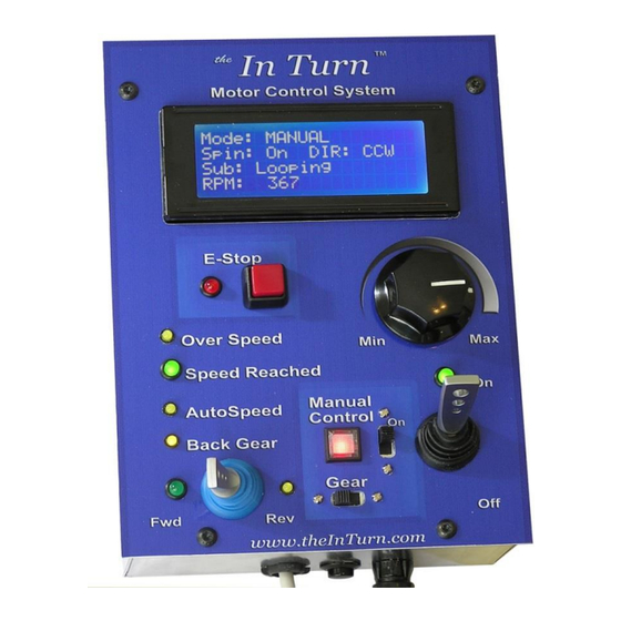
Load Meter: An animated real-time bar graph that displays the percentage of maximum motor torque being used. Manual Mode (obsolete): Condition for manually controlling the 4 axis for non MACH systems Reporting Mode: Condition where the Controller continuously scrolls the internally stored parameters. -
Page 30: Servo Motor Terminology
Servo Motor Terminology: Enable/Disable: The ability of a drive to release the motor to freewheel (disabled). Encoder: a device that is connected to the motor shaft and measures the motor rotation in small increments called ‘lines’ or ‘counts’. These are converted into electrical pulses that are sent to the servo Drive so that the motor position is known. - Page 31 Unfortunately, these ’names’ cannot be changed to something descriptive of what you are actually using them for. If you used ‘OUTPUT#15’ to control the InTurn™ Spindle lock, for example, it would be more comprehensible if the name ‘OUTPUT#15’ could be changed to ‘InTurn™ Spindle Lock’.
- Page 32 Some of these boards have rows of screw terminals for the signals and therefore do not require a separate BOB. Likewise, the InTurn™ 4 Axis Motor Controller has a dedicated DSS mounted on a separate small PC board with screw terminals for the needed signal wires and also contains the chips needed for the ‘swapaxis’...
Need help?
Do you have a question about the 4th Axis Mill/Turn Motor Control System and is the answer not in the manual?
Questions and answers