Advertisement
Quick Links
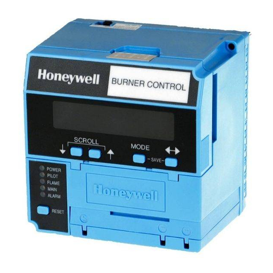
EC7820A 7800 SERIES
Relay Modules
APPLICATION
The Honeywell EC7820 is a microprocessor-based integrated
burner control for automatically fired gas, oil, or combination
fuel single burner atmospheric with fan (EC7820A)
applications. The EC7820 Relay Module system consists of a
relay module, wiring subbase, amplifier, and purge card.
Options include: keyboard display module (KDM), Data
ControlBus Module™, remote display mounting and
Modbus™ Module. Functions provided by the relay modules
include automatic burner sequencing, flame supervision,
system status indication, system or self diagnostics and
troubleshooting.This document provides installation and static
checkout instructions.
Other applicable publications are:
65-0084 Q7800A,B 22-Terminal Wiring Subbase
Product Data.
65-0089 ST7800A Plug-In Purge Timer Installation
Instructions.
65-0090 S7800A Keyboard Display Module Product
Data.
65-0091 S7810A Data ControlBus Module™ Product
Data.
65-0097 221729C Dust Cover Packing Sheet.
65-0109 R7824, R7847, R7848, R7849, R7851,
R7852, R7861, R7886 Flame Amplifiers for the 7800
SERIES Product Data.
65-0131 221818A Extension Cable Assembly
Product Data.
65-0229 7800 SERIES Relay Modules Checkout and
Troubleshooting Product Data.
65-0249 ModBus Module (S7810M1029 only).
INSTALLATION INSTRUCTIONS
SPECIFICATIONS
Electrical Ratings, See Table 4:
Voltage and Frequency: 220-240 Vac (+10/-15%), 50/ 60
Hz (±10%).
Power Dissipation: 10W maximum.
Maximum Total Connected Load: 2000 VA.
Fusing Total Connected Load: 15A maximum, type SC
or equivalent.
Environmental Ratings:
Ambient Temperature:
Operating: -40°F to 140°F (-40°C to 60°C).
Storage: -40° F to 150° F (-40°C to +66°C).
Humidity: 85% relative humidity continuous,
noncondensing.
Vibration: 0.5G environment.
SIL 3 Capable:
SIL 3 Capable in a properly designed Safety Instrumented
System. See form number 65-0312 for Certificate
Agreement.
Approvals:
Factory Mutual Approved: Report No. J.I.0Y0A9.AF.
Swiss Re (formerly Industrial Risk Insurers): Acceptable.
European Directives:
Gas Appliance Directive: 90/269/EEC.
Low Voltage Directive: 73/23/EEC.
EMC Directive: 89/336/EEC.
GASTEC: CE-63AP3070/1.
Approved according to EN298, "Automatic gas burner
systems for gas burners and gas burning appliances with
or without fans.
European Radiated
Emission Standard - EN50091
SIL
3
Capable
66-1091-08
Advertisement

Related Manuals for Honeywell EC7820A


Summary of Contents for Honeywell EC7820A
- Page 1 Electrical Ratings, See Table 4: burner control for automatically fired gas, oil, or combination Voltage and Frequency: 220-240 Vac (+10/-15%), 50/ 60 fuel single burner atmospheric with fan (EC7820A) Hz (±10%). applications. The EC7820 Relay Module system consists of a Power Dissipation: 10W maximum.
-
Page 2: Installation
EN 50081 (European Radiated Emission death or property damage. Standard). Observe applicable local safety requirements each time a See Fig. 1 for the internal block diagrams of the EC7820A control is installed on a burner. Relay Modules. Location WARNING Electrical Hazard or Equipment Damage Hazard. - Page 3 EC7820A 7800 SERIES RELAY MODULES Mounting Wiring Subbase 7. Use recommended wire routing of lead wires: a. Do not run high voltage ignition transformer wires in See Fig. 1 for the internal block diagrams of the relay the same conduit with the flame detector, Data Con- modules.
- Page 4 EC7820A 7800 SERIES RELAY MODULES Table 2. Recommended Practice Ground Type Recommended Practice Earth ground (subbase and relay 1. Use to provide a connection between the subbase and the control panel of the module) equipment. Earth ground must be capable of conducting enough current to blow the 15A fuse (or breaker) in the event of an internal short circuit.
- Page 5 EC7820A 7800 SERIES RELAY MODULES Final Wiring Check CAUTION 1. Check the power supply circuit. The voltage and fre- Equipment Damage Hazard. High voltage dielectric quency tolerance must match those of the 7800 test can cause equipment damage. SERIES Relay Module. A separate power supply circuit Do not perform a dielectric test with the 7800 SERIES Relay may be required for the 7800 SERIES Relay Module.
- Page 6 EC7820A 7800 SERIES RELAY MODULES Table 4. EC7820 Static Checkout. Voltmeter Test Test Normal Operation If Operation is Abnormal, Check the Items Listed Below Jumpers 1. Master Switch. None 5-L2 Line voltage at terminal 5. 2. Power connected to master switch.
- Page 7 AS REQUIRED. FIELD WIRING TO CONNECT L1 DIRECTLY TO LOS, AT LEAST ONE CONTROLLED M8032C INTERNAL WIRING SHUTDOWN MUST BE PROVIDED EVERY 24 HOURS. Fig. 1. Internal block diagram of EC7820A Relay Module (see Fig. 2 for detailed wiring instructions). 66-1091—08...
- Page 8 STEP-DOWNTRANSFORMER MUST BE INSTALLED TO DRIVE THE SHUTTER. POSTPURGE TIMING REFER TO AMPLIFIER AND FLAME DETECTOR SPECIFICATIONS FOR SELECT VIA ST7800A PURGE TIMER CARD WIRING DETAILS. M11630B SELECT VIA CONFIGURATION JUMPERS OR MODEL NUMBERS Fig. 2. Wiring subbase and operation sequence for EC7820A Relay Module. 66-1091—08...
-
Page 9: Principal Technical Features
PRINCIPAL TECHNICAL FEATURES SERIES Relay Module for the flame amplifier mounting. The EC7820A Relay Module provides all customary flame b. Allow an optional three-inch minimum on both sides safeguard functions while providing significant advancements of the 7800 SERIES Relay Module for electrical sig- in the areas of safety, annunciation, and system diagnostics nal voltage probes. - Page 10 EC7820A 7800 SERIES RELAY MODULES Safety Shutdown (Lockout) NOTE: Some devices allow five ignition attempts. Occurs If: 5. Ignition terminal is not energized. 6. Pilot valve/intermittent pilot valve terminal is not energized. INITIATE Period: 7. Main valve terminal is energized.
-
Page 11: Operation
EC7820A 7800 SERIES RELAY MODULES OPERATION Ignition Trials 1. Preignition: a. The ignition transformer, terminal 10, are energized Sequence of Operation for three seconds. First Safety Time (SAFETY1): The 7800 SERIES Relay Module has the operating a. With the Low Fire Switch input closed: sequences listed below. -
Page 12: Settings And Adjustments
Fig. 4. Selectable site-configurable jumpers. SETTINGS AND ADJUSTMENTS Selectable Site-Configurable Jumpers Table 5. Site configurable jumper options. The EC7820A Relay Module has three site-configurable Jumper jumper options, see Fig. 4 and Table 5. If necessary, clip the Number Description Intact...
Need help?
Do you have a question about the EC7820A and is the answer not in the manual?
Questions and answers