Table of Contents
Advertisement
Quick Links
KRT2-S, KRT2-L, KRT2-P
VHF Communication
285942-xx(xx)-xx(xx) = KRT2-S (Standard Ø57mm)
285945-xx(xx)-xx(xx) = KRT2-L (Mini Landscape)
286048-xx(xx)-xx(xx) = KRT2-P (Mini Portrait)
285946-xx(xx)-xx(xx) = KRT-RC (Remote control Ø57mm for KRT2)
Operation- and Installation
Operation and Installation Manual
KRT2 VHF-Communication Transceiver
Transceiver
Manual
Doc.-No: KRT2.A-MAN.en
Rev. 0101
Page 1
Advertisement
Table of Contents

Summary of Contents for TQ KRT2-S
- Page 1 Doc.-No: KRT2.A-MAN.en Rev. 0101 KRT2 VHF-Communication Transceiver KRT2-S, KRT2-L, KRT2-P VHF Communication Transceiver 285942-xx(xx)-xx(xx) = KRT2-S (Standard Ø57mm) 285945-xx(xx)-xx(xx) = KRT2-L (Mini Landscape) 286048-xx(xx)-xx(xx) = KRT2-P (Mini Portrait) 285946-xx(xx)-xx(xx) = KRT-RC (Remote control Ø57mm for KRT2) Operation- and Installation Manual...
-
Page 2: Record Of Revisions
Operation and Installation Manual Doc.-No: KRT2.A-MAN.en Rev. 0101 KRT2 VHF-Communication Transceiver Record of Revisions Revision Date Topic 0100 24.03.2017 Initial Release 0101 16.01.2018 FCC supplements Table 1: Record of Revisions Page 2... -
Page 3: Service Bulletins (Sb)
Operation and Installation Manual Doc.-No: KRT2.A-MAN.en Rev. 0101 KRT2 VHF-Communication Transceiver Service Bulletins (SB) Service Bulletins must be inserted in the manual and added to this table. No SB Release date Date added Name No Rev. Table 2: Service Bulletins Page 3... -
Page 4: Table Of Contents
Operation and Installation Manual Doc.-No: KRT2.A-MAN.en Rev. 0101 KRT2 VHF-Communication Transceiver Table of Contents Record of Revisions ........................2 Service Bulletins (SB) ........................3 GENERAL ..........................7 Symbols ..........................7 Acronyms .......................... 7 Customer Service ......................8 KRT2 Transceiver properties ..................... 8 Installation limitation ........................ - Page 5 Frequency / channel - schedule ..................53 Technical Data ........................ 54 List of Figures Figure 1: KRT2-S Front View ......................10 Figure 2: KRT2-P front view ....................... 11 Figure 3: KRT2-L front view ....................... 12 Figure 4: KRT2 active & standby frequencies ..................26 Figure 5: KRT2 TX &...
- Page 6 Figure 11: KRT2-S Dimensions ......................49 Figure 12: KRT2-P, KRT2-L dimensions .................... 50 Figure 13: KRT2-RC remote control dimensions ................50 Figure 14: KRT2-S panel cutout ......................51 Figure 15: KRT2-P, KRT2-L panel cutout ................... 51 List of Tables Table 1: Record of Revisions ....................... 2 Table 2: Service Bulletins ........................
-
Page 7: General
Operation and Installation Manual Doc.-No: KRT2.A-MAN.en Rev. 0101 KRT2 VHF-Communication Transceiver 1. GENERAL This manual contains information about the physical, mechanical and electrical properties as well as a description for the operation and installation of the VHF airborne transceiver KRT2. 1.1 Symbols WARNING Non-compliance may cause personnel injury due to radiation or fire. -
Page 8: Customer Service
KRT2 VHF-Communication Transceiver 1.3 Customer Service In order to process returned units most expeditiously, please use the email support.krt@tq-avionics.com on the website www.tq-avionics.com. Suggestions which will improve this manual are very much appreciated at: info@tq-avionics.com. Information concerning software updates is available under support.krt@tq-avionics.com. -
Page 9: Installation Limitation
Operation and Installation Manual Doc.-No: KRT2.A-MAN.en Rev. 0101 KRT2 VHF-Communication Transceiver 2. Installation limitation The conditions and tests required for (E)TSO approval of this article are minimum performance standards. It is the responsibility of those installing this article either on or within a specific type or class of aircraft to determine that the aircraft installation conditions are within the (E)TSO standards. -
Page 10: Control General
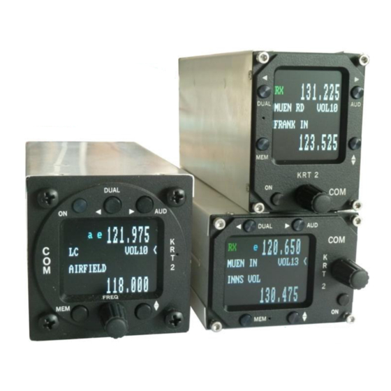
Operation and Installation Manual Doc.-No: KRT2.A-MAN.en Rev. 0101 KRT2 VHF-Communication Transceiver 3. CONTROL general 3.1 Control elements overview Figure 1: KRT2-S Front View Page 10... -
Page 11: Figure 2: Krt2-P Front View
Operation and Installation Manual Doc.-No: KRT2.A-MAN.en Rev. 0101 KRT2 VHF-Communication Transceiver Figure 2: KRT2-P front view Page 11... -
Page 12: Figure 3: Krt2-L Front View
Operation and Installation Manual Doc.-No: KRT2.A-MAN.en Rev. 0101 KRT2 VHF-Communication Transceiver Figure 3: KRT2-L front view All functions and performances of the normal size unit (57mm round) and the Portrait format (Mini) are identical. The only differences are the text areas on the display Compare Figure 2: KRT2 Front view and Figure 3: KRT2 Mini Front view for more details. -
Page 13: Table 4: Krt2 Controls
Operation and Installation Manual Doc.-No: KRT2.A-MAN.en Rev. 0101 KRT2 VHF-Communication Transceiver Button Function Usage ON / OFF Self-locking switch 1. Scanning between the Active and Standby fre- quencies DUAL WATCH 2. Positioning cursor to the left when programming the station identifier 1. -
Page 14: Display
Operation and Installation Manual Doc.-No: KRT2.A-MAN.en Rev. 0101 KRT2 VHF-Communication Transceiver 3.2 Display Indication Meaning Remark Reception RX is displayed during reception (squelch opened) Transmission Transmitter operates normally Transmitter was turned off automati- cally after 2 min continuous operation 119.700 Frequency ZELL SEE Frequency station identifier... -
Page 15: Menu Levels
Operation and Installation Manual Doc.-No: KRT2.A-MAN.en Rev. 0101 KRT2 VHF-Communication Transceiver Menu levels Displayed Signification Remark Volume Default Squelch Voice operated Voice operated intercom Display brightness BAT(tst) DC source check Intercom - Volume Volume of external devices TX(m)** PTT button selection Left/Right/Both Side tone During transmitter operation... -
Page 16: Operation
Operation and Installation Manual Doc.-No: KRT2.A-MAN.en Rev. 0101 KRT2 VHF-Communication Transceiver 4. OPERATION 4.1 General In the normal operating mode in which the turning knob always is connected to the volume (VOL). The normal operating mode can be left by pressing the AUD, FREQ or MEMORY button. When not in the normal mode and there is no pilot action for more than 10 seconds the unit returns to the normal mode. -
Page 17: Frequency Selection
Operation and Installation Manual Doc.-No: KRT2.A-MAN.en Rev. 0101 KRT2 VHF-Communication Transceiver 4.3 Frequency selection There are two different frequency selection methods: • Direct Input • Selection from the favourite list (index 0-99) 4.3.1 Direct frequency selection The Standby-Frequency is set with the turning knob in 3 different ranges. The selected range is high- lighted and can be changed with the FREQ button. -
Page 18: Frequency Selection From Favourites List
Operation and Installation Manual Doc.-No: KRT2.A-MAN.en Rev. 0101 KRT2 VHF-Communication Transceiver 4.3.2 Frequency selection from favourites list By pressing and operating the turning knob a specific favourite list position can be accessed [xx] (xx = index 0 … 99). When frequency and station identifier have been defined, they will be dis- played in the Standby and station identifier windows. - Page 19 Operation and Installation Manual Doc.-No: KRT2.A-MAN.en Rev. 0101 KRT2 VHF-Communication Transceiver Termination and Save To save the entered identifier, press the key as the cursor is on the station name, “SAVE” will appear and the system will go back to the favourite selection. A sorting process can be activated by pressing the “MEM”...
-
Page 20: Aud - Audio Menu
Operation and Installation Manual Doc.-No: KRT2.A-MAN.en Rev. 0101 KRT2 VHF-Communication Transceiver 4.4 AUD – Audio menu Any action in the Audio Menu requires the pointer (<) to be next to the Audio menu window (see picture). When the pointer is next to the Standby frequency window, the pointer can be repositioned by pressing the AUD button once. -
Page 21: Vox - Intercom Voice Trigger Level Setting
Operation and Installation Manual Doc.-No: KRT2.A-MAN.en Rev. 0101 KRT2 VHF-Communication Transceiver 4.4.3 VOX – Intercom voice trigger level setting Pressing the AUD button twice enables the turning knob to change the voice level which triggers the intercom. The intercom voice trigger level must be set to a value which prevents normal cockpit noise from be- ing heard in the earphones. -
Page 22: Int - Intercom Volume
Operation and Installation Manual Doc.-No: KRT2.A-MAN.en Rev. 0101 KRT2 VHF-Communication Transceiver 4.4.6 INT – Intercom volume Pressing the AUD button four times enables the turning knob to set the intercom volume. INTnn Range: 1 – 9 4.4.7 EXT – External audio input volume Pressing the AUD button five times enables the turning knob to set the external audio input volume. -
Page 23: Bat - Battery Test
Operation and Installation Manual Doc.-No: KRT2.A-MAN.en Rev. 0101 KRT2 VHF-Communication Transceiver 4.4.9 BAT – Battery test Pressing the AUD button seven times enables the turning knob to display the battery voltage. 4.4.10 SIT – Side tone Pressing the AUD button eight times enables the turning knob to set the side tone volume (for gliders has to be set to 01). - Page 24 Operation and Installation Manual Doc.-No: KRT2.A-MAN.en Rev. 0101 KRT2 VHF-Communication Transceiver Menus L and R: By means of the turning knob the displayed microphone input channel amplifier gain (MIC-level 01 = low gain, 09 =high gain) can be selected individually. The microphone signal level is dynamically dis- played with a bar and a numeric value.
-
Page 25: Menu Lock
Operation and Installation Manual Doc.-No: KRT2.A-MAN.en Rev. 0101 KRT2 VHF-Communication Transceiver The display of microphone type (lower right side) is done upon activation of the microphone menu. When an Electret microphone is recognized, the values used are the one that were saved upon leav- ing the menu. -
Page 26: Dual Watch
Operation and Installation Manual Doc.-No: KRT2.A-MAN.en Rev. 0101 KRT2 VHF-Communication Transceiver 4.5 DUAL watch Because the communication transceiver KRT2 contains only one receiver, DUAL watch is achieved by alternating between the Active and Standby frequencies. The DUAL button activates and deactivates the dual watch function. Deactivation also can take place by pressing either the FREQ or MEMORY buttons. -
Page 27: Transmitter Operation
Operation and Installation Manual Doc.-No: KRT2.A-MAN.en Rev. 0101 KRT2 VHF-Communication Transceiver Summary: • Select the Standby frequency to be monitored in addition to the active frequency. • With the AUD button and turning knob set SQnn to 2 or higher. •... -
Page 28: Two Ptt Configuration
Operation and Installation Manual Doc.-No: KRT2.A-MAN.en Rev. 0101 KRT2 VHF-Communication Transceiver 4.6.1 Two PTT configuration There are two different PTT assigned for each of the left and right side microphones. This enables the deactivation of the unused one preventing additional noise and unintentional talking on transmission. In case there is just one PTT and multiple headsets in use both the PTT-L and PTT-R must be tied together, see chapter “4.4.5 TXm –... -
Page 29: Resetting To Factory Settings
Operation and Installation Manual Doc.-No: KRT2.A-MAN.en Rev. 0101 KRT2 VHF-Communication Transceiver 4.7 Resetting to factory settings Returning to the factory settings can only be initiated during power-up. To do this, during power-up the MEM and DUAL buttons must be pressed simultaneously and the display will show “SET DEFAULTS”. -
Page 30: Erase - Erasing Of Favourites List
Operation and Installation Manual Doc.-No: KRT2.A-MAN.en Rev. 0101 KRT2 VHF-Communication Transceiver 4.8.1 ERASE – erasing of favourites list When in the SET UP – Menu select the “ERASE“ sub-menu with the buttons next to the symbols (Exit, Y). Erasing the favourites (frequency and identifier) starts after the button has been pressed again. -
Page 31: Remote Control
Operation and Installation Manual Doc.-No: KRT2.A-MAN.en Rev. 0101 KRT2 VHF-Communication Transceiver 5. Remote Control Tandem-seat airplanes can be equipped with the KRT2RC Remote Control Unit. The remote control unit is connected to RS232 serial interface and enables selection of the most common settings like frequency, volume, squelch, VOX, display contrast and brightness. -
Page 32: Installation
The following data may be required for the radio station license application. Manufacturer TQ-Systems GmbH Type KRT2 EASA Number EASA.21O.10063547 P/N 285942-XX(XX)-XX(XX) KRT2-S P/N 285945-XX(XX)-XX(XX) KRT2-L Part Number P/N 286048-XX(XX)-XX(XX) KRT2-P P/N 285946-XX(XX)-XX(XX) KRT2RC Power Output Frequency: 117.975 – 137.000 MHz... -
Page 33: Fcc Related Issues
(2) l'utilisateur de l'émetteur-récepteur doit accepter tout brouillage radioélectrique subi, même si le brouillage est susceptible d'en compromettre le fonctionnement. 6.3.4 Modifications Notice: Changes or modifications made to this transceiver not expressly approved by TQ-Systems GmbH may void the FCC authorization to operate this equipment. Page 33... -
Page 34: Scope Of Delivery
Operation and Installation Manual Doc.-No: KRT2.A-MAN.en Rev. 0101 KRT2 VHF-Communication Transceiver 6.4 Scope of delivery Part Number Description KRT2 KRT2 - VHF Transceiver ZUB2 (4 pcs) Mounting screw KRT2 - for panels up to 3mm KRT2.A-MAN.0100 Operation Manual EASA Form 1 Table 10: Scope of delivery 6.5 Unpacking and inspecting the equipment Carefully unpack the equipment. -
Page 35: Microphone Connection
Operation and Installation Manual Doc.-No: KRT2.A-MAN.en Rev. 0101 KRT2 VHF-Communication Transceiver 6.7.1 Microphone connection Both the L (left) and R (right) microphone input channels can either be connected to standard micro- phones (standard signal level 1Vpp) or to dynamic microphones (standard signal level 5mV to 10mV). Input R has less sensitivity (30mV). -
Page 36: Speaker & Open Microphone
Operation and Installation Manual Doc.-No: KRT2.A-MAN.en Rev. 0101 KRT2 VHF-Communication Transceiver Because the 8V supply voltage is switched off when dynamic microphones are used during glider flight the second (co-pilot) headset microphone is disabled. A maximum of two microphones of same type may be connected to each microphone input channel. Standard microphones have a large difference in power consumption;... -
Page 37: Final Audio Setup
Operation and Installation Manual Doc.-No: KRT2.A-MAN.en Rev. 0101 KRT2 VHF-Communication Transceiver 6.8 Final audio setup This is an overview for a correct audio set up depending on the usage. Ground the unused MIC.-R input if unused. 6.8.1 For glider flights •... -
Page 38: Wiring
Operation and Installation Manual Doc.-No: KRT2.A-MAN.en Rev. 0101 KRT2 VHF-Communication Transceiver 6.9 Wiring 6.9.1 Wire Gauges Supply lines (Power, GND): AWG20 (0,61 mm²) Control lines: AWG22 (0,38 mm²) All wires must be aviation certified. 6.9.2 Connector Pin-Configuration Figure 7: Connector pinout If manual intercom is not used, pin 12 should be grounded (Batt. -
Page 39: General Hint
Operation and Installation Manual Doc.-No: KRT2.A-MAN.en Rev. 0101 KRT2 VHF-Communication Transceiver The nine pins connector on the KRT2RC is used for the connection to the KRT2. 6.9.3 General hint The following drawings are not covering all possible configurations. There are many different micro- phones with sometimes incompatible performances on the marked. -
Page 40: Wiring Diagrams
Operation and Installation Manual Doc.-No: KRT2.A-MAN.en Rev. 0101 KRT2 VHF-Communication Transceiver 6.9.4 Wiring diagrams Two place motor aircraft connection Microphone-Setup: set L / R as required for headset, do not leave in AUTO Page 40... - Page 41 Operation and Installation Manual Doc.-No: KRT2.A-MAN.en Rev. 0101 KRT2 VHF-Communication Transceiver Glider two place connection Microphone-Setup: leave in L =11, (not AUTO) Page 41...
- Page 42 Operation and Installation Manual Doc.-No: KRT2.A-MAN.en Rev. 0101 KRT2 VHF-Communication Transceiver Glider single Microphone-Setup: leave with L =11 for dynamic, (not AUTO) Page 42...
- Page 43 Operation and Installation Manual Doc.-No: KRT2.A-MAN.en Rev. 0101 KRT2 VHF-Communication Transceiver Motor glider single Microphone-Setup: For Electret set L / R as required for headset, do not leave in AUTO-mode. For Dynamic, use a switch to cut off the dynamic mic. (If motoring) and leave setup in AUTO-mode, wire PTT-L and PTT-R in parallel.
- Page 44 Operation and Installation Manual Doc.-No: KRT2.A-MAN.en Rev. 0101 KRT2 VHF-Communication Transceiver Motor glider dual-Dynamic Microphone Dynamic Microphone Microphone-Setup: R for headsets, leave menu in AUTO mode. Page 44...
- Page 45 Operation and Installation Manual Doc.-No: KRT2.A-MAN.en Rev. 0101 KRT2 VHF-Communication Transceiver Motor glider dual-Electret Microphone Electret Microphone Microphone-Setup: leave L = 3..9 (in case of dynamic =11), R=3 (not AUTO-mode). Page 45...
-
Page 46: Wiring For Dynamic Microphones
Operation and Installation Manual Doc.-No: KRT2.A-MAN.en Rev. 0101 KRT2 VHF-Communication Transceiver 6.9.5 Wiring for dynamic microphones Special attention is required for the wiring for dynamic microphones. Because of the required high gain any mistake on the ground wiring leads to interferences and feed backs. The basic rules are: Never connect the power current grounds with the microphone ground. -
Page 47: Antenna
Operation and Installation Manual Doc.-No: KRT2.A-MAN.en Rev. 0101 KRT2 VHF-Communication Transceiver From left to right: From left to right: Pin 9: GND Mikrofon Pin 8: Batterie plus Pin 10: PTT-L Pin 7: Speaker + Pin 11: PTT-R Pin 6: Mikrofon R Pin 12: Intercom with Bridge to Gnd Pin 5: Ext. -
Page 48: Microphone General
Operation and Installation Manual Doc.-No: KRT2.A-MAN.en Rev. 0101 KRT2 VHF-Communication Transceiver 6.11 Microphone general The correct setting of the MIC and VOX values is of great importance for the Intercom system (see “4.4.3 VOX – Intercom Voice Trigger Level Setting” and “4.4.11 MIC – Setup”). The VOX intercom voice trigger level must be set to such a value that the intercom system is activat- ed when speaking at a normal voice level into the microphone. -
Page 49: Starting Up
The start display shows device type and the software number. It then changes into the normal operat- ing mode (Direct Input). 6.14 Accessories Suitable accessories such as antennas, cable sets, and switches can be purchased at our online shop on www.tq-avionics.com or from other avionics suppliers. 6.15 Drawings 6.15.1 Dimensions Figure 11: KRT2-S Dimensions Page 49... -
Page 50: Figure 12: Krt2-P, Krt2-L Dimensions
Operation and Installation Manual Doc.-No: KRT2.A-MAN.en Rev. 0101 KRT2 VHF-Communication Transceiver Figure 12: KRT2-P, KRT2-L dimensions Figure 13: KRT2-RC remote control dimensions Page 50... -
Page 51: Installation Directions
Operation and Installation Manual Doc.-No: KRT2.A-MAN.en Rev. 0101 KRT2 VHF-Communication Transceiver 6.15.2 Installation directions Required space for connectors Figure 14: KRT2-S panel cutout Figure 15: KRT2-P, KRT2-L panel cutout Page 51... -
Page 52: Maintenance
Operation and Installation Manual Doc.-No: KRT2.A-MAN.en Rev. 0101 KRT2 VHF-Communication Transceiver 7. Maintenance 7.1 Periodic Maintenance There are no scheduled service tasks required on the KRT-2 VHF unit. 7.2 Repair Only exchange and flat repair of the equipment is permitted. In case of equipment failure, the unit must be sent to the manufacturer. -
Page 53: Annex
Operation and Installation Manual Doc.-No: KRT2.A-MAN.en Rev. 0101 KRT2 VHF-Communication Transceiver 8. ANNEX 8.1 Frequency / channel - schedule The following table contains the operating and displayed frequencies between 118.000 and 118.100MHz. The table can be continued up to 137.000 MHz following the same principle. Operating frequency Cannel Spacing Displayed channel... -
Page 54: Technical Data
Operation and Installation Manual Doc.-No: KRT2.A-MAN.en Rev. 0101 KRT2 VHF-Communication Transceiver 8.2 Technical Data GENERAL Approval Number ETSO.21O.10063547 Compliance Standards ETSO-2C169a / TSO-C169a Transmitter: ED-23C Class 4,6 / DO-186B, Class 4,6 Receiver: ED-23C Class C-D-E-H1/2 / DO-186B, Class C-D-E Standards RTCA DO-186B / EUROCAE ED-23C RTCA DO-160F / EUROCAE ED14F RTCA DO-178C / EUROCAE ED12C, Software Level D... -
Page 55: Table 13: Technical Data Transmitter
Operation and Installation Manual Doc.-No: KRT2.A-MAN.en Rev. 0101 KRT2 VHF-Communication Transceiver TRANSMITTER Power Output 6 W (nominal) at >13.5V 4 W (minimal) Harmonic Distortion <10 % at 70 % modulation Sidetone Output >0,5W an 300Ω (head set output) Microphone Inputs 2 x standard (50mV…2V) into 100Ω...
Need help?
Do you have a question about the KRT2-S and is the answer not in the manual?
Questions and answers
How to I adjust the KRT-2 Side Tone and Squelch to get better radio clarity Especially in an open cockpit Bi-plane?
To adjust the TQ KRT2-S for better radio clarity in an open cockpit bi-plane:
Squelch (SQ):
- Press the AUD button once.
- Turn the knob to set the squelch level.
- Recommended setting: Start with SQ level 3–5.
- Lower SQ value increases sensitivity but may allow more noise; higher value reduces sensitivity and suppresses weak signals.
Side Tone:
- Side tone is heard in the headset and is disabled when no earphones are used.
- It is automatically turned off in certain conditions (e.g., VOX active, speaker output to prevent feedback).
- To ensure side tone is heard, use a headset and avoid using the speaker when VOX is active.
Proper settings help reduce background noise and improve clarity in noisy environments like an open cockpit.
This answer is automatically generated
Dzień dobry, Czym różni się wiązka kablowa ATR 500 od TQ KRT2-S ? Czy wiązka kablowa ATR 500 będzie kompatybilna z TQ KRT2-S ? Pozdrawiam Michał Byszkin
The ATR 500 wiring harness is not compatible with the TQ KRT2-S. The TQ KRT2-S uses a different connector pin layout and wiring configuration compared to the ATR 500. Therefore, a new or modified wiring harness must be used when installing the TQ KRT2-S.
This answer is automatically generated
Dzien dobry, Czym roznini sie wiazka ATR 500 od TQ KRT2-S ? Czy wiazka ATR 500 bedzie kompatybilna z TQ KRT2-S ? Pozdrawiam Michal Byszkin
The TQ KRT2-S requires a specific wiring harness for proper connection. An adapter (part number 61359) is available to connect the KRT2-S to the Funkwerk ATR 500/600 radios. This indicates that the ATR 500 wiring harness is not directly compatible with the TQ KRT2-S without using the adapter. The adapter ensures compatibility between the two systems.
This answer is automatically generated