
Summary of Contents for Motorvac TRANSTECH III
- Page 1 MOTORVAC TECHNOLOGIES INC. TRANSTECH III Transmission Service System User Manual modified pdf file version.
-
Page 2: Table Of Contents
Table of Contents Introduction............................iii Overview..............................4 System Features and Functions ...................... 1-1 Control Panel Features and Functions ..................1-2 Left View ............................1-3 Right View…………………………………………………………………………………………………1-4 Theory of Operation………………………………………………………………………………………1-5 Safety Information ..........................2-1 Before You Begin ..........................3-1 First Time Operation ........................3-1 Transmission Service Procedure .................... -
Page 3: Introduction
The TRANSTECH III System is a self-contained system; designed to connect to any automatic transmission through it’s cooling system lines. Once the unit is connected, it can be used to drain the fluid from the vehicle’s transmission for filter replacement and/or to completely exchange the... -
Page 4: Overview
Overview This manual contains all the information you need to use the TRANSTECH III System. Please make sure all technicians using the unit read this manual and have it within easy reach whenever the unit is being used. The following is a quick reference to the information in this manual: System Features and Functions This chapter describes the TRANSTECH III Transmission Service System’s Switches, Lights and Connections. -
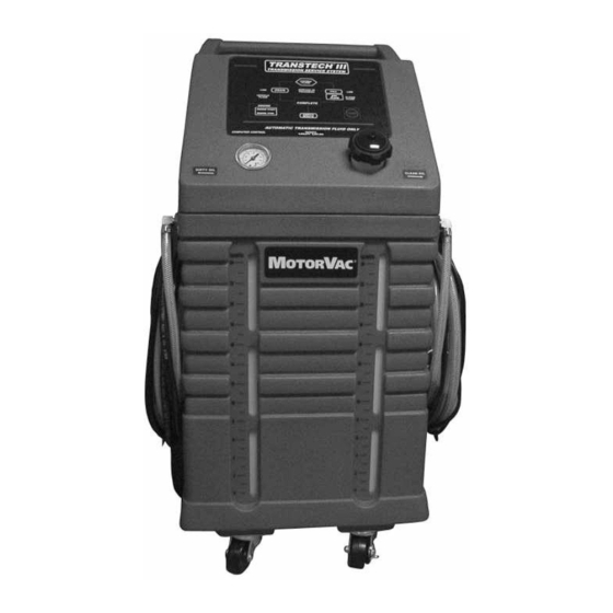
Page 5: System Features And Functions
System Features and Functions The front of the TRANSTECH III cabinet contains the control panel, the fluid fill neck for adding new transmission fluid, and the fluid level windows... -
Page 6: Control Panel Features And Functions
Front View - Control Panel Features and Functions Change Fluid Begins service - Starts exchanging new fluid for used fluid. NOTE: With DRAIN, FILL, and ENGINE START light on, service is in progress. Drain Drains fluid from vehicle’s transmission. When performing filter change, an alarm will sound when the transmission is empty. -
Page 7: Left View
Left View Adapter Tray Stores machine’s service adapters. Disposal hose Is inserted into the shop’s fluid recycling container or into a suitable container for proper disposal of used transmission fluid. Quick Coupler Secures the unit’s eturn hose connection to the adapter connected to the vehicle’s transmission‘s cooling system. -
Page 8: Right View
Right View Output Hose Connects to the transmission’s cooling system. Quick Coupler Secures the unit’s output hose connection to the adapter connected to the vehicle’s transmission’s cooling system. Serial plate Identifies the unit’s model and specific manufacturer’s production number. Battery Cables Positive (red) and negative (black) battery connections. -
Page 9: Theory Of Operation
Theory of Operations Descriptions of the various operations, control buttons, and indicators that make up the control panel are listed below. OFF MODE: When the unit is connected to power, an alarm will sound indicating power-up, and the ENGINE START light will be flashing. - Page 10 COMPLETE: The COMPLETE light will turn on at end of service or when the STOP button is pressed during the service. The unit will automatically revert to bypass mode. ENGINE START/ON: The light will flash if the engine needs to be started or if fluid flow needs increased. The light will be on solid when the engine is running indicating good flow from the vehicle.
-
Page 11: Safety Information
Safety Information and Precautions /!\ DANGER Vehicle exhaust gases contain Carbon Monoxide, which is a colorless and odorless lethal gas. Only run engines in well-ventilated areas and avoid breathing exhaust gases. Extended breathing of exhaust gases will cause serious injury or death. /!\ WARNING Exhaust gases, moving parts, hot surfaces are present during and after the vehicle’s engine is running. - Page 12 Do not store chemicals in or on the machine (other than automatic transmission fluid). Improper use of transmission fluid can cause injury. Over exposure can have harmful effect on eyes, skin, respiratory system and possible unconsciousness and asphyxiation. Improperly blocked vehicles can move. Set the parking brake and chock the wheels.
-
Page 13: Before You Begin
Before You Begin First Time Operation NOTE This unit has been tested using Dextron lll Automatic Transmission Fluid, and is ready for service after receiving inspection of the unit. Use new oil above 50 degrees Fahrenheit. Remember to send in your warranty card. -
Page 14: Transmission Service Procedure
Transmission Service Procedure Follow the steps below to connect the unit to the vehicle's transmission cooler lines. Make sure the vehicle has at least 1/8 tank of fuel before beginning this process. IMPORTANT Do not perform the transmission service if the vehicle’s engine oil or coolant level is low. - Page 15 Add the correct amount of automatic transmission fluid into the TRANSTECH’S clean tank reservoir. See chart below: APPROXIMATED FLUSH CHART 4 Cylinder vehicle 10-12 quarts 6 Cylinder vehicle 12-14 quarts 8 Cylinder vehicle 14-16 quarts NOTE: Quantity of fluid used per vehicle may vary depending on the condition of the fluid in the transmission being serviced.
- Page 16 With the vehicle’s engine running, the ENGINE START should be ON solid. Check the transmission fluid level. Feel the hoses for heat. Heat in both hoses will verify good bypass flow from vehicle, through the unit and back to vehicle. Transmission fluid will automatically circulate in bypass mode when unit is not on. If no bypass flow is indicated, DO NOT BEGIN SERVICE.
- Page 17 Let engine run for one minute, then check the transmission’s fluid level. If level is low: When complete light is on, and the low clean fluid light is on: Press and hold the FILL button for 10- 15 seconds. Re-check fluid level, repeat step “a)” if necessary. If level is high: When complete light is on, press and hold the DRAIN button for 10-30 seconds.
-
Page 18: Frequently Asked Questions
FLUID light goes out. Push the FILL button. When the tank runs dry, return unit to the upright position. Pump will stop. 2. The TransTech III seems to take longer to perform a service than when it was new. If it appears that a service now takes longer, inspect the clean tank filter screen for debris. Refer to the unit’s Filter Inspection on page A-1. -
Page 19: Troubleshooting And Additional Help
Troubleshooting and Additional Help Refer to the list below in the unlikely event that you have problems with your TRANSTECH III Transmission Service System. Problem: Solution: 1. Unit does not power-up, no LEDs are -Polarity is reversed on vehicle battery connection. Check lighted connection to battery for a loose condition. - Page 20 In the unlikely event that problems persist with the unit call Technical Support, have your model and serial numbers available before you call. Remember to send in your warranty card. U.S.A Canada: (800) 841-8810 Contact your local (714) 558-4822 MotorVac distributor...
-
Page 21: Appendix A - Maintenance
Appendix A - Maintenance Maintenance Procedures The following maintenance procedures should be performed on a routine basis: Carefully clean the exterior with a soft cloth to keep the cabinet looking new. Check the cabinet for dents or impact markings, if found, inspect for damaged components. Check all hoses and wires for cuts or frays. -
Page 22: Maintenance Record
Maintenance Record Use the following table to keep a record of maintenance performed on the unit. DRAIN FLUID CLEANED CLEAN EXT. CHECK HOSES TANKS FILTERS CABINET AND WIRES OTHER Initial/Date... -
Page 23: Appendix B - System Accessories
Most Asian Vehicles 060-1200 1/4” Open End Hose Most Asian Vehicles 060-1300 5/16” Open End Hose Most Asian Vehicles 060-1400 3/8” Open End Hose Most Asian Vehicles 060-1500 Hose Clamp 7/8” I.D. max 060-0450 General Application ¤ 2006 MotorVac Technologies, Inc. - Page 24 5/16” Female Flare-Deep 062-2060 Ford Vehicles Use with 062-0100 (Replaces 062-0110) 3/8” Male Flare-Deep Ford Vehicles Use with 062-1034 062-0120 (or 062-0130 in old kits) 3/8”Female Flare-Deep Ford Vehicles Use with 062-0120 062-1034 (Replaces 062-0130) ¤ 2008 MotorVac Technologies, Inc.
- Page 25 #5 SAE x #6 SAE Union 061-0605 European Vehicles Use with 062-0140 or 060-3800 5/16” Female Flare 062-0170 x 1/4” MPT General Application Use with 060-1700 3/8” Female Flare 062-0180 x 1/4” MPT General Application Use with 060-1800 ¤ 2008 MotorVac Technologies, Inc.
- Page 26 Use with 062-2040 061-1550 1/2” Male Tube with Locking Quick Connect Chrysler V-10 Diesel Use with 061-1550 062-2040 3/8” Male Tube with Locking Quick Connect G.M. 95 & up Vehicles Use with 060-1500 (Replaces 062-2050) 062-2066 ¤ 2008 MotorVac Technologies, Inc.
- Page 27 060-2742 Euro / Asia Vehicles Use with 060-2740 MQD X 1/4” FPT General Application 080-0592 Use with 080-0593 16mm x 1.5 Bubble Flare European Vehicles Use with 060-2300 & 060-2700 (not included or 060-2600 shown) ¤ 2008 MotorVac Technologies, Inc.
- Page 28 TransTech Adaptors Optional Transmission Adapters The following adapters are available for the TRANSTECH III. The adapters listed are not included with any configured adapter kits and are not sold in sets. PART & NO. APPLICATION Volvo 850 Application Volvo V-70 All Wheel Drive...
- Page 29 (O-Ring P/N: 080-3402) 080-0593 BMW (Jaguar & Mercedes) 10mm Female Receptacle / Flange Style Counterpart Adaptor: 062-2010 062-2015 / Female Side Adapter “sorter” rack for drain tray. 011-5014 (Standard equipment after Jan. 1,2006 build date). ¤ 2008 MotorVac Technologies, Inc.
- Page 30 Note: Pull O’Ring from 062-2065 oil filter & install in the Note: The center hole is ¾” ID x adaptor. 20 thread pitch. 062-2072 G.M. (CADILLAC CTS) ¤ 2008 MotorVac Technologies, Inc.
- Page 31 Reduces flow from ‘High-flow” vehicles – installs on ‘incoming’ ‘dirty’ fluid line between vehicle & Transtech-III unit. #6 SAE Flare European Vehicles Use with 061-0605 062-0140 MQD X 1/4” MPT General Application 080-0593 Use with 080-0592 ¤ 2008 MotorVac Technologies, Inc.
Need help?
Do you have a question about the TRANSTECH III and is the answer not in the manual?
Questions and answers