
Summary of Contents for Marksman MCU-100N
- Page 1 MCU-100N USER MANUAL TEL: +82-31-776-0803~6 FAX: +82-31-776-0807 Web-page: www.pinmarking.com E-mail: isaac@pinmarking.com...
- Page 2 INDEX General information Installation FUNCTION and operation program Handling of Keyboard F1 (M_MANU) MODE F2 (A_MARK) MODE F3 (Edit) MODE F4 (File) MODE F5 (Setup) MODE F6(Test) MODE F7(Font & Plt Load) MODE F8(Communication) MODE Control to the marking machine by PC Create PLT file by AUTO-CADR14 Maintenance Appendix...
- Page 3 The marking pin has a low sound level of less than”60db,”has acquired the patent and registration, and has been produced since Jan 2000 Marksman is manufactured and confirmed by the Europe CE certification standards “security, endurance, and electromagnetic wave standards, etc”...
- Page 4 MARKING HEAD MK100-115 (Standard type) MK100-90J (Dust cover) MK073 MK-054 (Portable type) MK100-BS (Ball screw type) MARKING CONTROLLER MCU-100N(Built in the keyboard) MCU-200BN MARKING PIN LP-06 LP-10 PLP-10 PH-16...
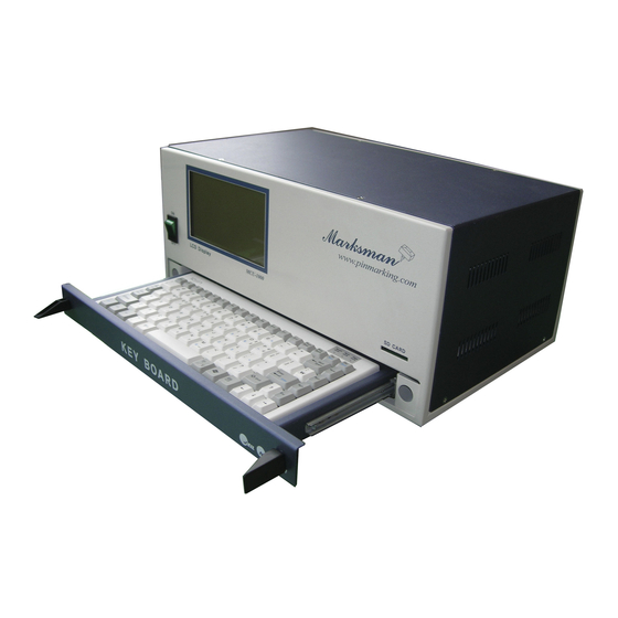
- Page 5 메인 전원SW Main power S/W Lamp SD card slot SD카드 삽입구 상태지시등 LCD 화면 Pin selector 마킹핀방식선택 Marksman www.pinmarking.com MCU-100N Display 메인 전원SW 스테핑 드라이버 SD카드 삽입구 K EY B OA RD 상태지시등 Clamping screw 고정나사 M3X4 LCD 화면 마킹핀방식선택...
- Page 6 installation Matters to be attended to before installation Main source of electricity: AC220Volt, 1ph, 3Ampare Cable connection: All cables need to be installed by being connected fast without being bent or twisted. Installation of Marking Head Installation should take place so that the distance between the Pin and the surface of work piece should be 3.5~4.5mm with a deviation of ±10mm.
- Page 7 Puncher sound level In general, the puncher sound increases when the board is thin and the clamp is not steadily attached. Sound cover attached: 55db, with silencer: under 50db Puncher with weighty substance in open space: 72db with silencer: 56db Puncher with a board less than 2 t in open space: 87db with silencer: 68db Soundproof cover for a board less than 2 t in open space: 65db, with silencer: 50db.
- Page 8 F1 MANUAL MARK MODE...
- Page 9 F1)Screen : M_MENU (Manual marking) F1 : M_MENU F2 : A_MARK F3 : EDIT F4 : FILE F5 : SETUP F6 : TEST F7 : LOAD F8 : COMM [MANUAL MARK MODE] BLK NO. [ 000 ] X : 0300 Y : 0300 A : 000 FNT : STD1...
- Page 10 F2 AUTO MARK MODE...
- Page 11 F2 Screen : A_MARK F1 : M_MENU F2 : A_MARK F3 : EDIT F4 : FILE F5 : SETUP F6 : TEST F7 : LOAD F8 : COMM [AUTO MARKING MODE] BLK NO. [ 000 ] MARK_UP_TO[ 00000000 ] UNIT_NO[00001713] <...
- Page 12 PLC INPUT SIGNAL [ ..] [ ..] STROBE PLC6 PLC5 PLC4 PLC START PLC3 START PLC2 RESET PLC1 STOP PLC0 *STROBE from above pics. is in case of ASCII communication. In case of model selection, it is recognized PLC7* 09:30:31 : Indicate the current time 0.00 : The cycle time of previous marking data (unit: sec)
- Page 13 * PLC Signal binary table* BLOCK BLOCK BLOCK BLOCK ... . ! . ! ! . . . ! . ! ! . . . ! . . . ! .
- Page 14 F1 : M_MENU F2 : A_MARK F3 : EDIT F4 : FILE F5 : SETUP F6 : TEST F7 : LOAD F8 : COMM [AUTO MARKING MODE] BLK NO. [ 00.00 ] MARK_UP_TO[ 00000000 ] UNIT_NO[00001713] < CURRENT DATA > PLC INPUT SIGNAL [ .
- Page 15 F3 EDIT MODE (F3) Screen : EDIT (LINEAR MARKING) Screen F1 : M_MENU F2 : A_MARK F3 : EDIT F4 : FILE F5 : SETUP F6 : TEST F7 : LOAD F8 : COMM [EDIT MODE] BLK NO. [ 000 ] X : 0300 Y : 0300 A : 000...
- Page 16 BLK NO.[000] : Block number. : Select the marking type. (Select the marking type using SPACE BAR) EMT : Empty block (Default value) LIN : Linear marking. CIR : Circular marking. PLT : Logo file marking after loading CAD file. CYL : Cylinder marking.
- Page 17 FONT : Select the letter type.(If press the SPACE BAR, Menu was changed.) STD1 = Standard font. Normal type. Letter of Aspect Ratio is 4:6 (W:L) STD2 = Gothic style. Letter of Aspect Ratio is 4:6 (W:L) STD3 = KS A 0203 Korean standard font DOT = 5*7 DOT style.
- Page 18 PAUSE:N 일경우 PAUSE:Y 일경우 마킹완료후 원점위치로 마킹완료후 마지막 마킹위치 Return to Home position after Stop after marking at the 자동복귀 에서 신호(Ex.START 또는 RESET ) marking automatically last marked position. 대기 DATA Screen : Input the data All letters and fonts in the keyboard can be used. Ex) JEIL MTECH CO.,LTD Can not mark"@"...
- Page 19 : Select marking type. Press SPACE BAR to change the Menu EMT : Empty block (Default value) LIN : Linear marking. CIR : Circular marking. PLT : Logo file marking after loading CAD file. CYL : Cylinder marking. 2DM : 2D Data matrix marking <LIN>...
- Page 20 > When the center of work piece and the X,Y and R value of circle doesn`t match each other The center of The letters The letters The letters is in letters and P r o b l e m Normal are leaned to the are leaned to the the circle...
- Page 21 FONT : Select the letter type.(If press the SPACE BAR, Menu was changed.) STD1 = Standard font. Normal type. Letter of Aspect Ratio is 4:6 (W:L) STD2 = Gothic style. Letter of Aspect Ratio is 4:6 (W:L) STD3 = KS A 0203 Korean standard font DOT = 5*7 DOT style.
- Page 22 P is pause P: Y = The pin wait for the next signal after last letter is marked. (To wait for next time start signal) Not output END signal P: N = The pin returns back to home automatically. DATA Screen : Input the data All letters and fonts in the keyboard can be used.
- Page 23 <LIN> <CIR> <PLT> <CYL> <2DM> ABCDEF ABCDEF 2D DATA Linear Circular Logo 로고마킹 직선마킹 원호마킹 2D Data 원주면마킹 MATRIX Cylinder Marking marking 마킹 Marking marking marking X : Center of circle for X axis from Zero point (30mm is X:0300 <Unit : 0.1mm> Y: Center of circle for Y axis from Zero point (30mm is X:0300 <Unit : 0.1mm>...
- Page 24 L : It doesn`t impact to the PLT file marking. I: It doesn`t impact to the PLT file marking. P is pause P: Y = The pin wait for the next signal after last letter is marked. (To wait for next time start signal) Not output END signal P: N = The pin returns back to home automatically.
- Page 25 F3 Screen: Cylinder marking F1 : M_MENU F2 : A_MARK F3 : EDIT F4 : FILE F5 : SETUP F6 : TEST F7 : LOAD F8 : COMM [EDIT MODE] BLK NO. [ 000 ] X : 0300 Y : 0300 R:150 A:000 FNT : STD1...
- Page 26 적용모델: MK-200, MK-073 Y-Axis Motor A: Direction of the marking. In case you set the marking machine like above pics. A:000 -> Marking toward X+direction based on Zero point A:090 -> Marking toward Y- direction based on Zero point A:180 -> Marking toward X-direction based on Zero point A:270 ->...
- Page 27 FONT : Select PLT file on the F7 PLOT LOAD. (Press SPACE BAR to change the menu) Loading 4 PLT file to PLT1 ~ 4 and then load the PLT file on the F7 PLOT LOAD. (Refer to Pg 51) <...
- Page 28 PAUSE:N 일경우 PAUSE:Y 일경우 마킹완료후 원점위치로 마킹완료후 마지막 마킹위치 Return to Home position Return to Home position 자동복귀 에서 신호(Ex.START 또는 RESET ) after marking automatically after marking automatically 대기 DATA Screen : Input the data All letters and fonts in the keyboard can be used. Ex) JEIL MTECH CO.,LTD Can not mark"@"...
- Page 29 F3 Screen: 2D MATRIX edit mode What is the 2D DATA MATRIX? 2D has a good function which store a lot of data more than 1D bar code. 2D is recognized by 2D reader and 2D can be stored a lot of data. Therefore it is suitable to the mark of the automated line. In this mode, when it marks the inputted data and number.
- Page 30 F1 : M_MENU F2 : A_MARK F3 : EDIT F4 : FILE F5 : SETUP F6 : TEST F7 : LOAD F8 : COMM [EDIT MODE] BLK NO. [ 000 ] X : 0300 Y : 0300 A :000 SIZE : 16X16 DP:050 L:00000000 I:00...
- Page 31 X:30mm X:30mm A:000 A:090 A:180 A:270 % Delicate adjustment of X and Y value on F3 mode % 0152 0152 0151 Press + 0151 X:0150 Y:0150 X : 0150 Y : 0150 (After move the cursor like the above) 0149 Press - 0149 0148 0148...
- Page 32 SIZE : Select the no. of cell during 2D DATA MATRIX marking. Please see the below chart for the reference of the data for each size. SIZE Alp. Cha. SIZE Alp. Cha. AUTO 3116 2335 8 x 18 C12 X 12 8 x 32 C14 x 14 12 x 26...
- Page 33 L : Creation increase and decrease of serial number. EX)(00000010) = First serial marking number is 10 In case you want to use automatic serial number, please key in @L@ according to no. of serial figures. @LLLL@ : Lot number 0001.0002.0003……0010 I : Creation increase and decrease of serial number.
- Page 34 (F3) Screen: Edit PLC SEQUENCE mode (Press F3 F3 twice to use this mode) F1 : M_MENU F2 : A_MARK F3 : EDIT F4 : FILE F5 : SETUP F6 : TEST F7 : LOAD F8 : COMM [SEQUENCE EDIT] SOOO // H / B000 /H SOO1 // H / B001 /H SOO2 // H / B002 /H...
- Page 35 F4 DATA MODE...
- Page 36 F4 Screen : Block and sequence data, store and load of setup information. If press “F4” on the KEY BOARD, it is changed like MARKING DATE LOAD => MARKING DATA SAVE => SEQUENCE FILE LOAD => SEQUENCE FILE SAVE => ALL SETUP LOAD => ALL SETUP SAVE <MARKING DATA LOAD >...
- Page 37 <SEQUENCE FILE LOAD> F1 : M_MENU F2 : A_MARK F3 : EDIT F4 : FILE F5 : SETUP F6 : TEST F7 : LOAD F8 : COMM [SEQUENCE FILE LOAD] FILE NAME [ FILENAME DATA TIME >< NO FILE > STATUS [ F4 : SEQUENCE FILE SAVE The function, the stored sequence file of the controller that you setting up on the F3 mode, loads...
- Page 38 <ALL SETUP LOAD> F1 : M_MENU F2 : A_MARK F3 : EDIT F4 : FILE F5 : SETUP F6 : TEST F7 : LOAD F8 : COMM [ALL SETUP LOAD] FILE NAME [ FILENAME DATA TIME >< NO FILE > STATUS [ F4 : SEQUENCE DATA SAVE The function that to load setting value in controller stores to the SD card.
- Page 39 F5 SETUP MODE...
- Page 40 F5 ( SETUP )Screen : PARAMETER F1 : M_MENU F2 : A_MARK F3 : EDIT F4 : FILE F5 : SETUP F6 : TEST F7 : LOAD F8 : COMM [ SETUP MODE] MARK SPEED [ 02000 ] MOVE SPEED [ 12000 ] ACCEL.
- Page 41 X MOTOR [10000] steps/100mm. : Standard: 10000purse per 100mm If the value of X MOTOR [10000] STEPS/100MM is changed, Marking machine may work incorrectly because the figure of marking machine is wrong. Do not modify. MK-100BS , MK-85BS , SI-120 - > STEP [ 25000 ] Another all other marking head그...
- Page 42 ECHO MARK DATA TO HOST? : Transfer the log data by RS-232 port after marking ( Default is [Y] ) MOVE X THEN Y TO OFFSET ? : Select the order of marking direction during marking pin is progressing. Select the axis which is moving earlier . ->...
- Page 43 Press “Enter”, the screen is changed as below : F1 : M_MENU F2 : A_MARK F3 : EDIT F4 : FILE F5 : SETUP F6 : TEST F7 : LOAD F8 : COMM [ SETUP MODE] X PARK POSITION [0000] 0.1mm./step Y PARK POSITION [0000] 0.1mm./step Reset Every...
- Page 44 X PARK POSITION [0000] 0.1mm./step : X axis of Virtual origin which marking pin will come after marking is finished in case using this function. ( Unit : 0.1 mm ) Y PARK POSITION [0000] 0.1mm./step : Y axis of Virtual origin which marking pin will come after marking is finished in case using this function.
- Page 45 (F5) Screen : Team code. Year, Month, day, etc (Activated by press F5F5 twice) F1 : M_MENU F2 : A_MARK F3 : EDIT F4 : FILE F5 : SETUP F6 : TEST F7 : LOAD F8 : COMM [ DATE CODE SET ] TEAM CODE 1.[ A ] = FROM [00:00:00] TO [07:59:59] 2.[ B ] = FROM [08:00:00] TO [15:59:59]...
- Page 46 Can see the below screen if press “Enter” on the above screen. F1 : M_MENU F2 : A_MARK F3 : EDIT F4 : FILE F5 : SETUP F6 : TEST F7 : LOAD F8 : COMM [ DATE CODE SET ] YEAR CODE Y-0[ A ] Y-1[ B ]...
- Page 47 F6 TEST MODE...
- Page 48 F6 ( TEST ) Screen : Check the condition of each parts and moving and modify the date and time on the controller. F1 : M_MENU F2 : A_MARK F3 : EDIT F4 : FILE F5 : SETUP F6 : TEST F7 : LOAD F8 : COMM [ TEST MODE]...
- Page 49 F7 FILE LODE MODE...
- Page 50 F8 : COMM [FONT LOAD] LOAD TO [USR1] FONT FILENAME DATA TIME COLUMBIA.BLK 1998/06/05 12:45 MARKSMAN.BLK 1998/06/05 12:45 JEILMTECH.BLK 1998/06/05 12:45 < NO FILE > STATUS [ F7 : PLOT LOAD Selected font will be loaded into the MCU if you press “Enter”key on the keyboard after select the font.
- Page 51 F8 : COMM [PLOT LOAD] LOAD TO [PLT1] PLOT FILENAME DATA TIME COLUMBIA.PLT 1998/06/05 12:45 MARKSMAN.PLT 1998/06/05 12:45 JEILMTECH.PLT 1998/06/05 12:45 < NO FILE > STATUS [ F7 : FONT LOAD Selected PLT file will be loaded into the MCU if you press “Enter”key on the keyboard after select the PLT file.
- Page 52 F8 COMMUNICATION MODE...
- Page 53 F8 ( COMM ) screen: COMMUNICATION mode F1 : M_MENU F2 : A_MARK F3 : EDIT F4 : FILE F5 : SETUP F6 : TEST F7 : LOAD F8 : COMM [ COMMUNICATION MODE] BLK NO [000] X : 0500 Y : 0500 A:000 FNT : STD1...
- Page 54 A. Sending data from PC ---> MK-100 Note :: Meaning of <ESC> is 1B at Hexadecimal and it is the space which input “ESC” on the keyboard Meaning of <CAN> is 18 at Hexadecimal and it is the space which input “CTRL-X”on the keyboard (Communication Mode Commends) Function Command...
- Page 55 Marking <ESC>L000; Select marking direction direction (Refer to Pg.13 Marking direction) Radius of circle <ESC>K000; Given the radius value of circle. R Direction of <ESC>P1; D:W- , Counterclockwise direction marking circular marking <ESC>P2; D:W+ , Clockwise direction marking Selection of Increase and decrease of serial number Selection of Increase <ESC>R+9;...
- Page 56 ** Getting data from MCU. To get data from the MK100, you must send a <ESC>? Sequence. Handle the problem of RS-232 communication by reconfirming data if use this function. All command word which come from MCU is just add “?” from command word that you gave to MC from PCU.
- Page 57 Example of communication mode F1 : M_MENU F2 : A_MARK F3 : EDIT F4 : FILE F5 : SETUP F6 : TEST F7 : LOAD F8 : COMM [EDIT MODE] BLK NO. [ 000 ] X : 0300 Y : 0300 A : 000 FNT : STD1 CH:030...
- Page 58 References on the Communication mode program The above examples can be expressed as 16 digits(Hexadecimal) as follows. 1. 1B 40 3B //Initialization 2. 1B 47 31 3B // Select LINEAR marking 3. 1B 48 30 3B // Select STD1 Font 4.
- Page 59 How to Create PLT file by standard AUTO CAD 2006...
- Page 60 How to create PLT File (By AUTO CAD 2006 LT) 1. Install new plotter before create PLT file. Put the cursor on Command window on Autocad and Then click right button of mouse. Then select Option.(O) 2. Below screen is indicated if select option(O). Then select the tab of Print and plot configuration.
- Page 61 4. Below screen is indicated. Click the Next.(N). 5. Another screen is indicated if you click next. Select “My computer” and click “Next”(N). 6. Select the plotter “HP (Hewlett-Packard) 7475A” .
- Page 62 7. Select Plot(F) on file. 8. Set the name of plotter and click “Next” (N). Use dafault value 7475A. 9. Click Finish(F) after plotter configuration.
- Page 63 10. Below screen is indicated if PLOT setting window is opened by command word. Select 7475A on Print and Plot configuration and then click Register(R). 11. Add the user`s paper size. Below screen is indicated if click paper size and click to Add.(A)
- Page 64 Select Start from scratch(S) if the below screen indicated and click “Next”(N). 13. Determine the paper size. Set the width and height to 100. Check the unit of it is mm. Click to Next.(N) 14. Determine possible printing area. Set all value “0”. Click to Next.(N)
- Page 65 15. Determine the size of user`s paper. In order to use default value, do not modify and click :Next”(N). Enter the file name of user paper size. In order to use default value, do not modify and click :Next”(N). 17. Setting of new paper size is done. Click “Finished”(F).
- Page 66 18. Select 7475A same as below and select the paper size 100 x 100 mm. Set the scale 1:1. You may display of PLOT as screen display or select the window. 19. Plot which will be output is indicated same as below if click “Preview”(P). 20.
- Page 67 MAINTENANCE MAINTENANCE Trouble Shooting Backup and recovery of Marking data Appendix MARKING HEAD Assembly PLC&I/O INTERFACE ASCII CODE and DATA Example of Input Auto marking DATA How to change the motor How to change the driver ◆ How to change CPU / IO board ◆...
- Page 68 Be careful of the trespass of paint, metal chip & dust into MCU u Checking the exhaust fan & filter u Increase of misprint, check in the pin assembly Servicing the Marksman When Marking machine doesn`t work : Symptom...
- Page 69 When the location of marking data is changed : Symptom Checklist Changed the location of marked data Check the coordinate of X and Y. ( Unit of coordinate is 0.1mm. Refer to Pg.12 F3 EDIT ) Check the tension of timing belt and PULLY which are connected with X and Y axis stepping motor.
- Page 70 When marking depth is not steady. Symptom Checklist When marking depth is not steady Clear marking holder using `WD40’cleaner. (Refer to Pg.43) pressure between 4~4.5Kg/cm pressure between 1.5~2.5Kg/cm Set the distance between the tip of marking pin and work piece properly.. PH PIN : App.
- Page 71 Maintenance of the marking pin: O-RING PH16 PIN LP10 PIN SPRING SPRING PH16 PIN HOLDER LP10 PIN HOLDER PH-16 LP-10 PH16 조립도 PH16 분해도 LP10 조립도 LP10 분해도 Disassembling & Assembling 1.Take out “O ring”and spring 2.Assembling is in the reverse order. Cleaning of the marking pin If the pin has some problem due to the metal chip, and water ,and dust ,please spray the cleaner “WD40”into the pin and start the vibration test.
- Page 72 마킹헤드 구성도 Marking Head Assembly No . P a r t d e sc r i p t i o n P a r t n o . Q t y 헤드프레임 MK100-001 헤드커버 MK100-002 X축 모터 조립 앗세이 MK100-003 Y축...
- Page 74 ** How to use ASCII code @GGGGGG@ How to make the data Set the no. of data using @G@ and then transfer the data And then transfer the data depending on no. of@G@ INP.CHAR, Digits Indicate the progressing of ASCII If transfer the ASCII CODE data to the CODE data controller one by one, can see the number...
- Page 75 ASCII Code Decimal Hexadecimal Octal Decimal Hexadecimal Octal Binary no. ASCII Binary no. ASCII numeral Numeral 0x00 0000 0000 0x40 0100 0000 0x01 0000 0001 0x41 0100 0001 0x02 0000 0010 0x42 0100 0010 0x03 0000 0011 0x43 0100 0011 0x04 0000 0100 0x44...
- Page 76 0x25 0010 0101 0x65 0110 0101 0x26 0010 0110 & 0x66 0110 0110 0x27 0010 0111 0x67 0110 0111 0x28 0010 1000 0x68 0110 1000 0x29 0010 1001 0x69 0110 1001 0x2A 0010 1010 0x6A 0110 1010 0x2B 0010 1011 0x6B 0110 1011 0x2C...
- Page 77 Advance Programming INPUT MARKING Letter & symbol marking 12ABab!% 12ABab!% Auto serial numbering I = +1 @LLLL@ 1000->1001->1002 (Variable = @L@) I = +2 @LLLL@ 1000->1002->1004 I = -1 @LLLL@ 1000->0999->0998 Auto serial numbering using I = +1 , AAA->AAB->AAC all letter &...
- Page 78 **Application of marking automatic variable **** ** The letters which are between each ‘@’ are recognized as marking variable. Ex.) In case of @YYYY@ , Marking machine mark the current year ‘2013’ , In case of @YY@YY , Last 2 no. of current year and YY letters are marked like ‘08YY’. *** Marking variable can be combined through only 1 times ‘@ ~ @’.
- Page 82 How to change stepping motor 1. Open the marking head by tool. 2. Disconnect the connector of motor in the marking head .
- Page 83 3. After disconnected the connector of motor, loosen a nut. 4. Loosen 4 pcs of hexagon head bolt which fix the stepping motor.
- Page 84 5. Take out the motor and install new motor to the marking head. 6. Push the Pully to opposite side to adjust the tension of timing belt.
- Page 85 7. Check the tension of the timing belt and then tighten up the nut of Pully.. 8. Connect the connector 1 by 1 according to the no. and cover the upper plate of marking head.
- Page 86 How to change the stepping driver 1. Loosen the screws of the controller to open it. Indicated Red circle is Stepping driver.. 3. Above is the pictures of Micro=-stepping driver.
- Page 87 4. Loosen 4 screws which are in the center in the pictures. 5. Can separate the stepping driver if you pick it up after loosen the screws . 6. Specification of stepping drivers for both axis are same each other.
- Page 88 How to change I/O 1. Loosen the screws of the controller to open it. 2. Can see the I/O board which is located next to stepping driver. 3. Loosen the screw which is support I/O board and then pick it up . 4.
- Page 89 JS-1000V 4.0 Marking Program construction <<F2 MARK MENU>> 1. Function of ICON on the top of screen are as following . - F2 Mark : Can give START, STOP , RESET signal to the controller. - F3 Edit : Modify the data and import saved data on the s/w. - F4 Setup : Adjust the step of motor and timing of sol.
- Page 90 <<F3 EDIT MENU>> 1. Above picture is as following. - BlkNo : Block no.. 00 is single block and 00.00 is multi block. - Type : Select the marking type. - Font : Select the font. - Hght : Select the height of letters. - Px : Adjust the distance between the center of each letters.
- Page 91 <<F4 SETUP>> 1. Solenoid Valves - ON Delay : The delay time of sol. Valve when the marking is started. - OFF Delay : The delay time of sol. Valve when the marking is finished. - Dot ON : After arrive marking position, activate Sol. Valve work set amount time. - Dot OFF : The time of moving upto the marking location at DOT font.
- Page 92 << F5 Load >> 1. User1 ~ User4 - Loading USER font. Can load user font if click Browse. 2. User5 ~ User10 : The function we don`t use.. 3. Plot1 ~ Plot4 - Loading PLOT file which user created. Can load PLOT file if click Browse 4.
- Page 93 << F6 Option >> 1. COM Port : Set the CORPORT of the S/W. COMPORT between P.C and JS-1000 S/W must be the same all the time. 2. Multi Line : Check on the “Multi line”when you use Multi block. 3.
- Page 94 How to Modify the data of block modify the time of the controller...
- Page 95 How to modify the data of block 1. Open the keyboard drawer to the bottom of controller. 2. Below screen is indicated if press F3 on the keyboard. F1 : M_MENU F2 : A_MARK F3 : EDIT F4 : FILE F5 : SETUP F6 : TEST F7 : LOAD...
- Page 96 How to modify the time of controller 1. Press F6 on the keyboard . F1 : M_MENU F2 : A_MARK F3 : EDIT F4 : FILE F5 : SETUP F6 : TEST F7 : LOAD F8 : COMM [ TEST MODE] X_HOME X_LIMIT Y_HOME...
- Page 97 Bank-up the data to the SD card 1. Press [F4] six times on the keyboard to move below screen. F1 : M_MENU F2 : A_MARK F3 : EDIT F4 : FILE F5 : SETUP F6 : TEST F7 : LOAD F8 : COMM [ALL SETUP SAVE] FILE NAME [...
- Page 98 How to change worker`s time and team code Press [F5] two times on the keyboard to move below screen F1 : M_MENU F2 : A_MARK F3 : EDIT F4 : FILE F5 : SETUP F6 : TEST F7 : LOAD F8 : COMM [ DATE CODE SET ] TEAM CODE...
- Page 99 How to change the date Below screen is indicated if keep press Enter key after press [F5] two times on the keyboard. F1 : M_MENU F2 : A_MARK F3 : EDIT F4 : FILE F5 : SETUP F6 : TEST F7 : LOAD F8 : COMM [ DATE CODE SET ]...
Need help?
Do you have a question about the MCU-100N and is the answer not in the manual?
Questions and answers
How to change manual mode to auto mode change settings