
Subscribe to Our Youtube Channel
Related Manuals for GREE ELECTRIC GWH12TB-S3DBA1E


Summary of Contents for GREE ELECTRIC GWH12TB-S3DBA1E
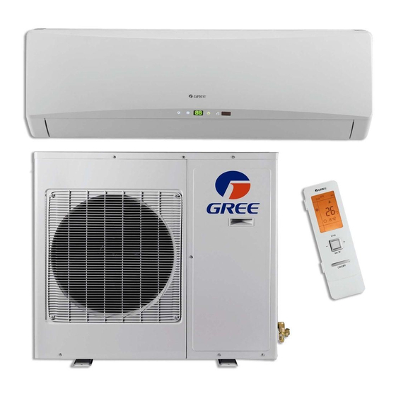
- Page 1 Change for Life Service Manual Models: GWH12TB-S3DBA1E GWH12TB-S3DBA2E GWH12TB-S3DBA3E (Refrigerant R410A) GREE ELECTRIC APPLIANCES,INC.OF ZHUHAI...
-
Page 2: Table Of Contents
Service Manual Table of Contents Part Ⅰ : Technical Information ...............1 1. Summary ........................1 2. Specifications ......................2 2.1 Specification Sheet ......................2 2.2 Operation Characteristic Curve ..................4 2.3 Capacity Variation Ratio According to Temperature ............4 2.4 Noise Curve ........................5 2.5 Cooling and Heating Data Sheet in Rated Frequency .............5 3. - Page 3 Service Manual 9. Maintenance ......................63 9.1 Troubleshooting for Normal Malfunction .................63 9.2 Error Code List .......................67 9.3 Troubleshooting for Main Malfunction ................72 10. Exploded View and Parts List ..............85 10.1 Indoor Unit ........................85 10.2 Outdoor Unit .........................88 11. Removal Procedure ..................90 11.1 Removal Procedure of Indoor Unit ................90 11.2 Removal Procedure of Outdoor Unit ................97...
-
Page 4: Part Ⅰ : Technical Information
Service Manual Part Ⅰ : Technical Information 1. Summary Indoor Unit: GWH12TB-S3DBA1E/I GWH12TB-S3DBA2E/I GWH12TB-S3DBA3E/I Outdoor Unit: GWH12TB-S3DBA3E/O Remote Controller: YAC1FB MODE TURBO SLEEP I FEEL TIMER ON TIMER OFF CLOCK QUIET X-FAN TEMP LIGHT Technical Information... -
Page 5: Specifications
Service Manual 2. Specifications 2.1 Specification Sheet Parameter Unit Value 1.GWH12TB-S3DBA1E Model 2.GWH12TB-S3DBA2E 3.GWH12TB-S3DBA3E 1.CB148009102 2.CB411003901 Product Code 3.CB412002902 CB412002903 Rated Voltage 220-240 Power Rated Frequency 50/60 Supply Phases Power Supply Mode Outdoor Cooling Capacity(Min~Max) 3500(1150~4000) Heating Capacity(Min~Max) 3650(2000-5300) Cooling Power Input(Min~Max) - Page 6 Service Manual Outdoor Unit Model GWH12TB-S3DBA3E/O Outdoor Unit Product Code CB412W02901 Compressor Manufacturer ZHUHAI LANDA COMPRESSOR CO., LTD Compressor Model QXAT-B096zE070 Compressor Oil 68EP Compressor Type Rotary Compressor Locked Rotor Amp (L.R.A) 40.00 Compressor Rated Load Amp (RLA) 5.40 Compressor Power Input 1130 Compressor Overload Protector 1NT11L-6233...
-
Page 7: Operation Characteristic Curve
Service Manual 2.2 Operation Characteristic Curve Cooling Heating Condition Condition Indoor:DB27°C WB19°C Indoor:DB20°C Outdoor:DB35°C WB24°C Outdoor:DB7°C Indoor air flow: Super High Indoor air flow:Super High Pipe length: 5m Pipe length: 5m Compressor speed (rps) Compressor speed (rps) 2.3 Capacity Variation Ratio According to Temperature Cooling Heating Cooling... -
Page 8: Noise Curve
Service Manual 2.4 Noise Curve Indoor Unit Outdoor Unit Super High Middle Middle Middle Quiet High High Compressor speed (rps) Indoor fan motor rotating speed (rps) 2.5 Cooling and Heating Data Sheet in Rated Frequency Cooling: Pressure of gas pipe Inlet and outlet pipe Rated cooling Compressor... -
Page 9: Outline Dimension Diagram
Service Manual 3. Outline Dimension Diagram 3.1 Indoor Unit Φ55 Φ55 Unit:mm Model Technical Information... -
Page 10: Outdoor Unit
Service Manual 3.2 Outdoor Unit Unit:mm Technical Information... -
Page 11: Refrigerant System Diagram
Service Manual 4. Refrigerant System Diagram INDOOR UNIT OUTDOOR UNIT GAS SIDE 3-WAY VALVE 4-Way valve Discharge HEAT EXCHANGE (EVAPORATOR) Accumlator Suction COMPRESSOR HEAT EXCHANGE (CONDENSER) Intercooler LIQUID SIDE Electron Strainer Strainer Strainer Capillary Strainer 2-WAY VALVE expansion valve COOLING HEATING Connection pipe specification: Liquid : 1/4"... -
Page 12: Electrical Part
Service Manual 5. Electrical Part 5.1 Wiring Diagram ●Instruction Symbol Symbol Color Symbol Symbol Color Symbol Name White Green Jumper cap Yellow Brown COMP Compressor Blue Grounding wire YEGN Yellow/Green Black Violet Orange Note: Jumper cap is used to determine fan speed and the swing angle of horizontal lover for this model. ●... - Page 13 Service Manual GWH12TB-S3DBA1E/I GWH12TB-S3DBA2E/I GWH12TB-S3DBA3E/I(CB412N02903) 600007000019 ● Outdoor Unit GWH12TB-S3DBA3E/O VA AC-L2 63610000231 These wiring diagrams are subject to change without notice; please refer to the one supplied with the unit. Technical Information...
-
Page 14: Pcb Printed Diagram
Service Manual 5.2 PCB Printed Diagram Indoor unit ● Top view 1 Grounding wire Interface of health function live wire Interface of health function neutral wire 4 Neutral wire 5 Interface of DC motor Interface of electrostatuc dedusting 7 Auto button 8 Up&down swing interface 1 9 eft&right swing interface 10 Up&down swing interface 2... - Page 15 Service Manual Outdoor unit ● Top view 14 15 ● Bottom view Technical Information...
-
Page 16: Function And Control
Service Manual 6. Function and Control 6.1 Remote Controller Introduction ON/OFF button MODE button FAN button TURBO button WIFI ▲/ button button button SLEEP button I FEEL button TIMER ON / TIMER OFF button CLOCK button QUIET button(This function is unavailable for this model) X-FAN button(Note: X-FAN is the same with BLOW.) LIGHT button... - Page 17 Service Manual 1. ON/OFF button Press this button can turn on or turn off the air conditioner. After turning on the air conditioner, operation indicator " "on indoor unit’s display is ON (green indicator. The colour is different for different models), and indoor unit will give out a sound. 2.
- Page 18 Service Manual ● Under swing left and right mode, when the status is switched from off to , if press this button again 2s later, status will switch to off status directly; if press this button again within 2s, the change of swing status will also depend on the circulation sequence stated above. button Press this button can select up &...
- Page 19 Service Manual "TIMER OFF" button can set the time for timer off. After pressing this button," "icon disappears and the word "OFF" on remote controller blinks. Press " ▲ " or " " button to adjust TIMER OFF setting. After each pressing " ▲ " or " "...
-
Page 20: Function Introduction For Combination Buttons
Service Manual ● When selecting " " or no display with remote controller, temperature indicator on indoor unit displays set temperature. ● When selecting " " with remote controller, temperature indicator on indoor unit displays indoor ambient temperature. ● When selecting " "... -
Page 21: Replacement Of Batteries In Remote Controller
Service Manual Replacement of batteries in remote controller 1. Press the back side of remote controller marked with " ", as shown in the fig, and then push out the cover of battery box along the arrow direction. 2. Replace two 7# (AAA 1.5V) dry batteries, and make sure the position of "+" polar and "-" polar are correct. 3. -
Page 22: Operation Of Smart Control (Smart Phone, Tablet Pc) For Gree
Service Manual 6.2 Operation of Smart Control (Smart Phone, Tablet PC) For Gree Operation Instructions Download and install APP Scan the following QR code with your smart phone and download Wifi Smart. Install the APP according to its guidance. When successfully installed, your smart phone homepage will show this icon User of IOS system can search for the Gree Smart in Apple store to download the Apple version APP. - Page 23 Service Manual Select "Add device" and enter the page of "Add device". Tap "Manual configuration" and enter the page "Manual configuration". Step 2: Select the correct network name and enter the password. Select the server (The server setting here must keep the same as the server setting in "Settings"...
- Page 24 Service Manual Step 4: If configuration is successful, a window will pop up and read "Configuration succeeded". Then configuration is completed. NOTE: After configuration is completed, the air conditioner hot spot connected to your phone will disAPPear. You should reconnect your phone to the home Wifi router to realize long-distance control.
- Page 25 Service Manual (4) If password is forgotten, you can reset the password with your email address. Tap "Forgot password" and enter the page "Forgot password". Tap "Get verification code" to get an email verification code. Enter a new password and tap "OK" to log in. 2.Personal settings Purpose: Set name (device name, preset name, etc.) and images (device image) in order to identify a user easily.
- Page 26 Service Manual (2) Set preset name Step 1: Tap at the top right corner of the homepage "Device". Select "Add preset" and enter the page "Preset edit". Step 2: Choose the time. Tap "Name". As shown in the picture, its name is "baby room". For timer type, select "On". Then select the repeating days.
- Page 27 Service Manual to increase or decrease temperature. Tap to change working mode. Tap to enter the page of fan speed adjustment. and go around the circle to adjust fan speed. Step 2: Advanced settings to enter advanced settings. You may select "Air", "Dry", "Health", "Light", "Sleep" or "Energy saving". (2) Advanced control functions: Set scene;...
- Page 28 Service Manual Tap "Add scene" and edit the scene name, for example, "Back home". Add execution devices. to add commands. On the page "Select execution device", select the air conditioner named "babyroom". Then select "ON" or "OFF". Continue to select the next execution device as instructed above. Tap to set the interval.
- Page 29 Service Manual (3) Preset includes single-device preset and multi-device preset Single-device preset: This can preset a certain device to be On/Off at a specific time. On the homepage "Device", take air conditioner "babyroom" as an example. Tap at the bottom of the page "babyroom". Then you will enter the page "Preset edit".
- Page 30 Service Manual (4) Link(This function is APPlicable to some models) Select a master device. When the environment satisfies the parameters as set in the master device, slave devices will execute commands to realize devices linkage. Step 1: Set the parameters of master device (Select master device, select environment parameters, select master device status). at the top right corner of the homepage "Device".
- Page 31 Service Manual Tap the days below "Repeat" to select the repeating days. Then tap "Save". Step 3: Select "Execute command" Tap "Execute command" and enter the page "Select device". Tap the name of device that you want to control. Tap "ON" or "OFF" and then tap "Save" to complete the linkage. Tap "Save"...
- Page 32 Service Manual (5) Infrared control (only APPlicable to smart phones with infrared emitter). Function: Smart phone can be used as a remote controller. at the top right corner of the homepage "Device". Select "Infrared" and enter the page "Remote controller". Tap slide up to enter the page of advanced functions.
- Page 33 Service Manual Step 2: Another smart phone to be imported. Tap the model name and wait for the download. (2) Backup: To keep backup of the quick configuration information and unit’s information, including backup to cloud and backup list on the cloud.
- Page 34 Service Manual (3) Settings User can set vibration, message alerts, server, updates, etc. The server setting here must be the same as the server setting in "Configuration" mentioned before. Otherwise, remote control will be invalid. (4) Feedback User can feedback suggestions to back-stage management for maintenance and development. Tap "Feedback".
-
Page 35: Operation Of Smart Control (Smart Phone, Tablet Pc)
Service Manual 6.3 Operation of Smart Control (Smart Phone, Tablet PC) Operation Instructions Download and install APP Scan the following QR code with your smart phone and download Wifi Smart. Install the APP according to its guidance. When successfully installed, your smart phone homepage will show this icon User of IOS system can search for the Wifi Smart in Apple store to download the Apple version APP. - Page 36 Service Manual 2.Configuration method for Android phones 4 steps of configuration Step 1: Enter homepage "Device", and then tap at the top right corner. Select "Add device" and enter the page "Add device". Tap "Manual configuration" and enter the page "Manual configuration". Step 2: Tap "Next"...
- Page 37 Service Manual NOTE: After configuration is completed, the air conditioner hot spot connected to your phone will disappear. You should reconnect your phone to the home WiFi router to realize long-distance control.The above configuration only needs onephone. Other types of phones shall install this APP, connect with the air conditioner hot spot or wireless router of WiFi air conditioner.
- Page 38 Service Manual If the name of router or the password is wrong, Wifi Smart can’t connect to the wireless router. 2 mins later, please conduct the configuration operation again. Reset Wi-Fi adaptor by pointing you remote at the indoor unit and holding the mode and Turbo buttons on your remote control for 10 seconds and until you hear the beep.
- Page 39 Service Manual 2.Personal settings Purpose: Set name (device name, preset name, etc.) and images (device image) in order to identify a user easily. (1) Set device name After quick configuration, a list of controllable smart devices will be generated. Default name for air conditioner is the last 8 numbers of the air condtioner mac address.
- Page 40 Service Manual (2) Set preset name Step 1: Tap at the top right corner of the homepage "Device". Select "Add preset" and enter the page "Preset edit". Step 2: Choose the time. Tap "Name". As shown in the picture, its name is "baby room". For timer type, select "On". Then select the repeating days.
- Page 41 Service Manual Tap "babyroom" and enter the page of air conditioner control. Tap to turn on the control switch. to increase or decrease temperature. Tap to change working mode. Tap to enter the page of fan speed adjustment. and go around the circle to adjust fan speed. Step 2: Advanced settings to enter advanced settings.
- Page 42 Service Manual Continue to select the next execution device as instructed above. Tap to set the interval. Tap "Save". Tap the scene picture displayed on homepage "Device" to send the command. Then the scene "Back home" will be in execution. You may view the execution condition of the scene. (3) Preset includes single-device preset and multi-device preset Single-device preset: This can preset a certain device to be On/Off at a specific time.
- Page 43 Service Manual Tap "Name" to customize the preset name. Preset device can’t be selected and it will default to "babyroom". Select "On" for the timer type. Select repeating days to complete the preset. Multi-device preset: This can preset multiple devices to execute a command at a specific time. Please refer to the instructions as how to set preset time, name, timer type and repeating days for a single device.
- Page 44 Service Manual Tap "Temperature" to enter the page "Select temperature parameter". Slide up or down to adjust temperature. Tap "Upper limit" or "Lower limit". Tap "Mode" and "On/Off" to select the status of master device. Then tap "Save". Step 2: Set time parameter for linkage. Tap "Time parameter" to enter the page "Set time". Slide rightwards to turn on the setting time.
- Page 45 Service Manual Tap the name of device that you want to control. Tap "ON" or "OFF" and then tap "Save" to complete the linkage. Tap "Save" and then repeat the above steps to set linkage of several scenes. 4.Menu functions Menu functions (Share, Set, History, Feedback) (1) Share: To share quick configuration information and unit’s information, including local export and local import.
- Page 46 Service Manual Step 2: Another smart phone to be imported. Tap the model name and wait for the download. Notice: This function requires that the two phones are of the same operating system. They are either Android phones or Apple phones,and are connecting to the same wireless router.
- Page 47 Service Manual (3) Settings User can set vibration, message alerts, server, updates, etc. The server setting here must be the same as the server setting in "Configuration" mentioned before. Otherwise, remote control will be invalid. (4) Help Please refer to “Help” of APP for the instruction of the latest functions. Technical Information...
-
Page 48: Brief Description Of Modes And Functions
Service Manual 6.4 Brief Description of Modes and Functions Indoor Unit ● 1.Temperature Parameters Indoor preset temperature (Tpreset) Indoor ambient temperature (Tamb.) 2.Basic functions (The temperature in this manual is expressed by Centigrade. If Fahrenheit is used, the switchover between them Tf=TcX1.8+32.) Once the compressor is energized, there should be a minimum interval of 3 minutes between two start-ups. - Page 49 Service Manual Stop heating preset Original operating status preset Start heating 6min. 3min. 6min. Compressor Outdoor fan <2 min. Indoor fan <2 min. preset preset wind wind Reversing valve Stop ② Defrosting and Oil Return When receiving the signal of defrosting and oil return, the horizontal louver(big one) will rotate to the position where the angle is minimum and the other horizontal louver(small one) will close.
- Page 50 Service Manual ③ In this mode, TURBO can’t be set and fan speed can’t be adjusted. ④ In this mode, when compressor operates, fan speed will be adjusted as follows; when compressor stops operation, indoor unit will operate at blowing residual heat. When Tindoor amb.
- Page 51 Service Manual Upon energization or availably operating the unit or remote controller, the buzzer will give out a beep. (4)Sleep Function Cooling mode、Dry mode: Basing on the set temperature of remote controller, after turning on the sleep function for a few hours, set temperature will increase properly and automatically according to human body’s comfort.
- Page 52 Service Manual swing function is set and indoor fan is operating. Note: a. If the position is set between O and D1, A 1and C1 or B1 and D1 by remote controller, the horizontal louver will swing between O and D1. b.
- Page 53 Service Manual will be displayed; if jumper cap has malfunction, “C5” will be displayed. (11)Memory Function ① Memory when power failure upon turning on the unit ◆ Memory content: ON status, mode, up&down swing, light, set temperature, set fan speed, general timer, Fahrenheit/ Centigrade ◆...
- Page 54 Service Manual Outdoor Unit ● 1. Compensation function of input parameters According to the structure of wall-mounting unit, considering the comfortability for operation, indoor ambient temperature when the compressor is at OFF status is higher than set temperature under heating mode. 2.
- Page 55 Service Manual operation due to freeze protection. If T ≥T and the compressor has stopped for 3min, the complete unit can inner tube temperature of freeze protection resume operation. 11.3 If the unit is stopped because of freeze protection for 6 times successively, it can’t resume operation automatically and the malfunction will be displayed continuously, which can only be resumed by pressing ON/OFF button.
-
Page 56: Part Ⅱ : Installation And Maintenance
Service Manual Part : Installation and Maintenance Ⅱ 7. Notes for Installation and Maintenance Safety Precautions: 10. If the power cord or connection wire is not long enough, please get the specialized power cord or connection wire Important! from the manufacture or distributor. Prohibit prolong the wire by yourself. - Page 57 Service Manual Safety Precautions for Installing and Relocating the Unit: To ensure safety, please be mindful of the following precautions. Warnings 1. When installing or relocating the unit, be sure to keep the refrigerant circuit free from air or substances other than the specified refrigerant.
- Page 58 Service Manual Main Tools for Installation and Maintenance 1. Level meter, measuring tape 2. Screw driver 3. Impact drill, drill head, electric drill 4. Electroprobe 5. Universal meter 6. Torque wrench, open-end wrench, inner hexagon spanner 7. Electronic leakage detector 8.
-
Page 59: Installation
Service Manual 8. Installation 8.1 Installation Dimension Diagram Space to the wall Space to the wall At least 15cm At least 15cm Drainage pipe Installation and Maintenance... -
Page 60: Installation Procedures
Service Manual Installation procedures Start installation Preparation before installation Read the requirements select installation Prepare tools for electric connection location Select indoor unit Select outdoor unit installation location installation location Install the support of outdoor unit Install wall-mounting frame, drill wall holes (select it according to the actual situation) Connect pipes of indoor Fix outdoor unit... -
Page 61: Installation Parts-Checking
Service Manual 8.2 Installation Parts-checking 8.4 Electric Connection Requirement 1. Safety Precaution Name Name (1) Must follow the electric safety regulations when installing Indoor unit Sealing gum the unit. Outdoor unit Wrapping tape (2) According to the local safety regulations, use qualified Support of outdoor Connection pipe power supply circuit and air switch. - Page 62 Service Manual (3) Fix the wall-mounting frame on the wall with tapping screws 5. Connect the Pipe of Indoor Unit (ST4.2X25TA) and then check if the frame is firmly installed by (1) Aim the pipe joint at the corresponding bellmouth.(As show pulling the frame.
- Page 63 Service Manual 7. Connect Wire of Indoor Unit 8. Bind up Pipe (1) Open the panel, remove the screw on the wiring cover and (1) Bind up the connection pipe, power cord and drain hose then take down the cover.(As show in Fig.11) with the band.(As show in Fig.14) (2) Reserve a certain length of drain hose and power cord for installation when binding them.
-
Page 64: Installation Of Outdoor Unit
Service Manual 8.6 Installation of Outdoor Unit Refer to the following table for wrench moment of force: 1. Fix the Support of Outdoor Unit(select it according to the Hex nut diameter(mm) Tightening torque(N m) actual installation situation) Φ6 15~20 (1) Select installation location according to the house structure. Φ9.52 30~40 (2) Fix the support of outdoor unit on the selected location with... -
Page 65: Vacuum Pumping And Leak Detection
Service Manual 8.8 Check after Installation and Test (3) The water outlet cant be placed in water in order to drain smoothly.(As show in Fig.27) Operation 1. Check after Installation Check according to the following requirement after finishing installation. The drain hose can't be fluctuant Items to be checked Possible malfunction Has the unit been... -
Page 66: Maintenance
Service Manual 9. Maintenance 9.1 Troubleshooting for Normal Malfunction Measure insulation resistance The breaker trips at once when it to ground to see if there is any is set to “ON”. leakage. Trip of breaker or blow of fuse The circuit or the part of the air conditioner has malfunction. - Page 67 Service Manual Improper set of temperature Adjust set temperature If cooling (heating) load is Check the forecasted load of cooling (heating) proper Check and fill the leakage, then The refrigerant has leakage or is vacuumize it and supplement the re- insufficient frigerant as required Leakage between the high pres-...
- Page 68 Service Manual The indoor fan motor is burned or breaks or has the heat protector Replace the fan motor or the defective part. malfunction. The built-in heat protector of the Replace the fan motor The fan does not motor breaks frequently because the run when it is set motor is abnormal.
- Page 69 Service Manual The torque of the swing motor is not enough First, check whether the connection is Wrong connection The swing fan wrong. If no, replace the parts does not run. The controller is damaged(IC2003 is damaged, the swing relay can not close, etc) C o n t r o l l e r m a l f u n c t i o n ( I C 2 0 0 3 Change controller...
-
Page 70: Error Code List
Service Manual 9.2 Error Code List Display Method of Outdoor Unit Indicator has 3 kinds of display Dual- status and during blinking, ON No. Malfunction Name 8 Code A/C status Possible Causes 0.5s and OFF 0.5s Display Yellow Green Indicator Indicator Indicator During cooling and drying... - Page 71 Service Manual Display Method of Outdoor Unit Indicator has 3 kinds of display Dual- status and during blinking, ON No. Malfunction Name 8 Code A/C status Possible Causes 0.5s and OFF 0.5s Display Yellow Green Indicator Indicator Indicator When the outdoor unit receive OFF 1s signal of Gathering refrigerant,the Gathering...
- Page 72 Service Manual Display Method of Outdoor Unit Indicator has 3 kinds of display Dual- status and during blinking, ON No. Malfunction Name 8 Code A/C status Possible Causes 0.5s and OFF 0.5s Display Yellow Green Indicator Indicator Indicator 1. Measure the voltage of position L and N on wiring board (XT), if the voltage is higher than 265VAC, turn on the unit after the...
- Page 73 Service Manual Display Method of Outdoor Unit Indicator has 3 kinds of display Dual- status and during blinking, ON No. Malfunction Name 8 Code A/C status Possible Causes 0.5s and OFF 0.5s Display Yellow Green Indicator Indicator Indicator After the complete unit is deenergized for 20mins, check "During cooling whether the thermal grease on...
- Page 74 Service Manual Display Method of Outdoor Unit Indicator has 3 kinds of display Dual- status and during blinking, ON No. Malfunction Name 8 Code A/C status Possible Causes 0.5s and OFF 0.5s Display Yellow Green Indicator Indicator Indicator "During cooling and drying Malfunction of operation,compressor will stop To protect the electronical...
-
Page 75: Troubleshooting For Main Malfunction
Service Manual 9.3 Troubleshooting for Main Malfunction ●Indoor unit: 1. Malfunction of Temperature Sensor F1, F2 Start Is the wiring terminal between temperature sensor and the controller loosened or poor ly contacted? Insert the temperature sensor tightly Malfunction is eliminated. Is there short circuit due to tri-pover of the pa rts? Make the parts upright... - Page 76 Service Manual 2. Malfunction of Blocked Protection of IDU Fan Motor H6 Start Turn the fan blades by hand under power-off condition Adjust the motor and blade Whether the fan blades assembly so that rotor can run can run smoothly? smoothly.
- Page 77 Service Manual 3. Malfunction of Protection of Jumper Cap C5 Troubleshooting for C5 malfunction Appearance of Is there jumper cap on the the jumper cap mainboard ? Assemble the jumper cap with the same model Is malfunction eliminated the jumper cap inserted correctly and tightly ? Insert the...
- Page 78 Service Manual 4. Communication malfunction E6 Start Cut off power, check if the wire between indoor unit and outdoor unit, and the wire inside electric box are connected correctly Reconnect the wire Malfunction is according to Connected correctly? eliminated wiring diagram Is there incorrect Match them match between the mainboard...
- Page 79 Service Manual 5. Malfunction of detecting plate(WIFI ) JF Start check if the connection wire are correctly connected detecting Replace the plate with the same model Is malfunction eliminated Replace the mainboard with the same model The end Installation and Maintenance...
- Page 80 Service Manual ●Outdoor unit: (1) Capacitor charge fault (Fault with outdoor unit) (AP1 below refers to the outdoor control panel) Main Check Points: ●Use AC voltmeter to check if the voltage between terminal L and N on the wiring board is within 210VAC~240VAC. ●Is the reactor (L) correctly connected? Is the connection loose or fallen? Is the reactor (L) damaged? Fault diagnosis process: Turn on the unit...
- Page 81 Service Manual (2) IPM Protection, Out-of-step Fault, Compressor Phase Overcurrent (AP1 below refers to the outdoor control panel) Main check points: ●Is the connection between control panel AP1 and compressor COMP secure? Loose? Is the connection in correct order? ●Is the voltage input of the machine within normal range? (Use AC voltmeter to measure the voltage between terminal L and N on the wiring board XT) ●Is the compressor coil resistance normal? Is the insulation of compressor coil against the copper tube in good condition? ●Is the working load of the machine too high? Is the radiation good?
- Page 82 Service Manual (3) High temperature and overload protection diagnosis (AP1 hereinafter refers to the control board of the outdoor unit) Mainly detect: ●Is outdoor ambient temperature in normal range? ●Are the outdoor and indoor fans operating normally? ●Is the heat dissipation environment inside and outside the unit good? Fault diagnosis process: Overheat and high temperature protection...
- Page 83 Service Manual (4) Start-up failure (following AP1 for outdoor unit control board) Mainly detect: ●Whether the compressor wiring is connected correct? ●Is compressor broken? ●Is time for compressor stopping enough? Fault diagnosis process: Power on the unit Restart it up after Is stop time of the compressor 3 minutes longer than 3 minutes?
- Page 84 Service Manual (5) Out of step diagnosis for the compressor (AP1 hereinafter refers to the control board of the outdoor unit) Mainly detect: ●Is the system pressure too high? ●Is the input voltage too low? Fault diagnosis process: Out of step occurs in Out of step occurs once the operation unit is powered on.
- Page 85 Service Manual (6) Overload and air exhaust malfunction diagnosis (following AP1 for outdoor unit control board) Mainly detect: ●Is the PMV connected well or not? Is PMV damaged? ●Is refrigerant leaked? Fault diagnosis process: 20 minutes after the complete unit is powered off Is the terminal FA for the Connect the...
- Page 86 Service Manual (7) Power factor correct or (PFC) fault (a fault of outdoor unit) (AP1 hereinafter refers to the control board of the outdoor unit) Mainly detect: ●Check if the reactor (L) of the outdoor unit and the PFC capacitor are broken Fault diagnosis process: Start Check wiring of the...
- Page 87 Service Manual (8) Communication malfunction: (following AP1 for outdoor unit control board) Mainly detect: ●Is there any damage for the indoor unit mainboard communication circuit? Is communication circuit damaged? ●Detect the indoor and outdoor units connection wire and indoor and outdoor units inside wiring is connect well or not, if is there any damage? Fault diagnosis process: Start...
-
Page 88: Exploded View And Parts List
Service Manual 10. Exploded View and Parts List 10.1 Indoor Unit MODE TURBO SLEEP I FEEL TIMER ON TIMER OFF CLOCK QUIET X-FAN TEMP LIGHT The component picture is only for reference; please refer to the actual product. Installation and Maintenance... - Page 89 Service Manual Part Code Description GWH12TB-S3DBA3E/I Product Code CB412N02902 CB412N02903 Front Panel 20022219T 20022240 Display Board 30565203 30565203 Filter Sub-Assy 1112211602 1112211602 Front Case Assy 20022256 20022256 Guide Louver 1051214702 10512127 Guide Louver 10512127 1051214702 Crank 10582070 10582070 Axile Bush 10542036 10542036 Helicoid Tongue sub-assy...
- Page 90 Service Manual Part Code Description GWH12TB-S3DBA1E/I GWH12TB-S3DBA2E/I Product Code CB148N09102 CB411N03900 Front Panel 20012850T 20022255T Display Board 30565140 30565145 Filter Sub-Assy 1112211602 1112211602 Front Case Assy 20012849 2001284902 Guide Louver 10512127 10512127 Guide Louver 10512147 1051214702 Crank 10582070 10582070 Axile Bush...
-
Page 91: Outdoor Unit
Service Manual 10.2 Outdoor Unit The component picture is only for reference; please refer to the actual product. Installation and Maintenance... - Page 92 Service Manual Part Code Description GWH12TB-S3DBA3E/O Product Code CB412W02901 Front Grill 22413015 Cabinet 01433034P Axial Flow Fan 10333011 Fan Motor 15013085 Electrical Heater (Chassis) 76510004 Chassis Sub-assy 0280311901P Drainage Joint 26113009 Compressor Gasket 76710287 Compressor and Fittings 00103899G Magnet Coil 4300008301 Compressor Overload Protector(External) 00180030...
-
Page 93: Removal Procedure
Service Manual 11. Removal Procedure Caution: discharge the refrigerant completely before removal. 11.1 Removal Procedure of Indoor Unit Steps Procedure 1. Before disassembling the unit Before disassembling the unit. 2. Remove filter Open the panel. Loosen the clasps on filter, push the filter inward and then pull it upward, then the filter can be removed. - Page 94 Service Manual Steps Procedure Remove the rotating shaft of big guide louver from the groove, slightly bend thebig guide louver to remove it. big guide louver Remove the axial bushing of small guide louver. axial bushing Remove the rotating shaft of small guide louver from the groove, slightly bend the small guide louver to remove it.
- Page 95 Service Manual Steps Procedure panel, to remove the display. 5.Remove front case screw detecting plate Remove the screw fixing detecting plate and remove the detecting plate. Note: The position of detection board(WIFI) may be different for different models. electric box cover2 Remove the screw fixing electric box cover2 and remove the electric box cover2.
- Page 96 Service Manual Steps Procedure 6.Remove swing fan blade Loosen the clamps fixing swing connecting rod, to remove the swing connecting rod. clamp swing connecting rod clamp remove the swing fan blade. swing fan blade 7.Remove electric box sub-assy heat exchanger thermistor Remove the indoor tube temp.
- Page 97 Service Manual Steps Procedure to remove the cover. electric box cover electric box cover sub-assy screw Remove every wiring terminals, and remove the electric box cover sub-assy. 7.Remove evaporator sub-assy auxiliary piping pipe clamp Remove the screws fixing connection pipe clamp, to remove the connection pipe clamp.
- Page 98 Service Manual Steps Procedure auxiliary piping Remove the screws fixing evaporator sub-assy, slightly regulate the tube, to remove the evaporator sub-assy. evaporator sub-assy 8.Remove cross fan blade and motor motor, to remove the motor. up&down swing motor to remove the motor. left&right swing motor Installation and Maintenance...
- Page 99 Service Manual Steps Procedure Remove the screws fixing motor clamp, to remove the motor clamp. screw motor clamp Remove the cross fan blade and motor. bearing cushion rubber base Remove the shafting bearing cushion rubber base cross fan blade motor blade and motor, and then remove the motor.
-
Page 100: Removal Procedure Of Outdoor Unit
Service Manual 11.2 Removal Procedure of Outdoor Unit Step Procedure 1. Remove top cover Remove the screws connecting top cover, left and right side plate, as well as panel, to remove the top top cover cover. 2. Remove handle and valve cover Remove the screws connecting handle and right side plate, to remove the handle.Remove the screw fixing valve cover, to remove the cover. - Page 101 Service Manual Step Procedure 4. Remove left side plate Remove the screws fixing left side plate and condenser support boa rd, to remove the left side plate. left side plate 5. Remove cross fan blade Remove the screw nut fixing cross fan blade, remove the gasket and spring cushion, to remove the cross fan blade.
- Page 102 Service Manual Step Procedure 7. Remove electric box assy electric box cover Remove screws fixing electric box assy and mid-isolation board, loosen the bonding tie, pull off the wiring terminal, lift to remove the electric box assy. electric box assy 8.
- Page 103 Service Manual Step Procedure flash vaporizer assy 10. Remove flash vaporizer assy Remove the screws connecting mid-isolation board, lift to remove the flash vaporizer assy. 11. Remove four-way valve assy four-way valve assy Welding cut the spot weld of four-way valve assy, compressor air suction/discharging valve and condenser pipe outlet, lift to remove the four-way valve assy.
- Page 104 Service Manual Step Procedure 13. Remove compressor compressor Remove the three feet screwnuts fixing compressor, to remove the compressor. 14. Remove big and small valve assy Remove screws connecting condenser assy and chassis, to remove the condenser assy. Remove the screws fixing big and small valve, to small valve remove the valves.
-
Page 105: Appendix
Service Manual Appendix: Appendix 1: Reference Sheet of Celsius and Fahrenheit Conversion formula for Fahrenheit degree and Celsius degree: Tf=Tcx1.8+32 Set temperature Fahrenheit Fahrenheit Fahrenheit display Fahrenheit display Fahrenheit display Fahrenheit Celsius (℃) Celsius (℃) Celsius (℃) temperature temperature temperature (℉)... -
Page 106: Appendix 3: Pipe Expanding Method
Service Manual Appendix 3: Pipe Expanding Method Pipe Note: Pipe cutter Improper pipe expanding is the main cause of refrigerant leakage.Please expand the pipe according to the following steps: Leaning Uneven Burr A:Cut the pip ● Confirm the pipe length according to the distance of indoor unit and outdoor unit. ●... -
Page 107: Appendix 4: List Of Resistance For Temperature Sensor
Service Manual Appendix 4: List of Resistance for Temperature Sensor Resistance Table of Ambient Temperature Sensor for Indoor and Outdoor Units(15K) Temp( C) Resistance(kΩ) Temp( C) Resistance(kΩ) Temp( Resistance(kΩ) Temp( Resistance(kΩ) 138.1 18.75 3.848 1.071 128.6 17.93 3.711 1.039 121.6 17.14 3.579 1.009... - Page 108 Service Manual Resistance Table of Tube Temperature Sensors for Outdoor and Indoor(20K) Temp( C) Resistance(kΩ) Temp( C) Resistance(kΩ) Temp( Resistance(kΩ) Temp( Resistance(kΩ) 181.4 25.01 5.13 1.427 171.4 23.9 4.948 1.386 162.1 22.85 4.773 1.346 153.3 21.85 4.605 1.307 20.9 4.443 1.269 137.2 4.289...
- Page 109 Service Manual Resistance Table of Discharge Temperature Sensor for Outdoor(50K) Temp( C) Resistance(kΩ) Temp( Resistance(kΩ) Temp( C) Resistance(kΩ) Temp( Resistance(kΩ) 853.5 18.34 4.75 799.8 93.42 17.65 4.61 89.07 16.99 4.47 703.8 84.95 16.36 4.33 660.8 81.05 15.75 4.20 620.8 77.35 15.17 4.08 580.6...
- Page 110 Tel: (+86-756) 8522218 Fax: (+86-756) 8669426 Email: gree@gree.com.cn Http://www.gree.com HONG KONG GREE ELECTRIC APPLIANCES SALES LIMITED Add: Unit 2612,26/F.,Miramar Tower 132 Nathan Road,TST,Kowloon,HK Tel: (852) 31658898 Fax: (852) 31651029 For product improvement, specifications and appearance in this manual are subject to change without prior notice.
Need help?
Do you have a question about the GWH12TB-S3DBA1E and is the answer not in the manual?
Questions and answers