
Subscribe to Our Youtube Channel
Summary of Contents for Lennox DC
- Page 1 USER MANUAL DC & DM displays BALTIC AIRCOOLAIR FLEXAIR COMPACTAIR ENERGY FLATAIR AQUALEAN DC-DM-IOM-1801-E www.lennoxemea.com...
-
Page 3: Table Of Contents
1.2 Temperature measurement ......................2 1.3 Quick Action ..........................3 1.4 Presentation ..........................6 1.5 Use ............................... 7 1.6 DC set in ‘Light’ mode ........................8 1.7 DC set in ‘Full’ mode ........................9 Setting Value ..........................11 1.9 Activation level 2 ........................11 Display ‘DM’... -
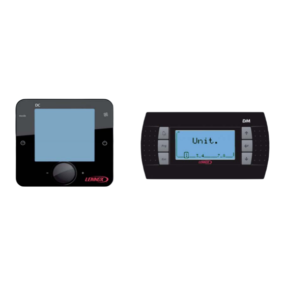
Page 4: Display 'Dc
All Lennox Unit comes with a temperature sensor; it must be placed in the conditioned area. But if the 'DC' is placed in the area conditioned by the Unit, it is possible, in this case, to use the temperature measurement of the 'DC'. -
Page 5: Quick Action
Press the knob to confirm your choice How to Start all Units connected at this DC ? 1.3.2 Press the button a few seconds. The units can not be powered On/Off by the DC if the service display DS is connected. DC-DM-ROOFTOP-IOM-1801-E - 3 -... - Page 6 Turn the knob to select number 1 (1 for ‘On’, 0 for ‘Off’). Press the knob to confirm your choice The units can not be powered On/Off by the DC if the service display DS is connected. How to See the Value of the Current Setpoint Temperature ? 1.3.4...
- Page 7 How to Modify the Value of the Current Setpoint Temperature ? 1.3.5 Turn the knob to have the text ‘Set’. Press the knob to switch in 'Set' mode. Turn the knob to change the value. Press the knob to confirm your choice DC-DM-ROOFTOP-IOM-1801-E - 5 -...
-
Page 8: Presentation
1.4 Presentation Showing 1.4.1 Buttons 1.4.2 DC-DM-ROOFTOP-IOM-1801-E - 6 -... -
Page 9: Use
Unit is stopped and the 'DC' in sleep mode. To restart the unit, press the button a few seconds If the DC is used with the Master/Slaves bus in this case, the 'Off' phase, stops all Rooftop connected on the Bus, 'On' phase restarts all. DC-DM-ROOFTOP-IOM-1801-E... -
Page 10: Dc Set In 'Light' Mode
* : Available if the option is enabled. : Adjustable with ‘DC. Unit selected 1.6.1 If the DC is used with the Master/Slaves bus this item can select or know the Unit Index selected by the 'DC'. DC-DM-ROOFTOP-IOM-1801-E - 8 -... -
Page 11: Dc Set In 'Full' Mode
This item can select or know the Unit Index selected by the 'DC'. On/Off, Power 1.7.2 If the DC is used with the Master/Slaves bus this item allows you to view and/or change the status of starting or stopping of the Unit selected. Volatile Temperature set point 1.7.3... - Page 12 This item indicates the measured value of the opening rate of the fresh air damper, in%, (mixture of outside air and return air) This value is only available if the Unit is equipped with this option. DC-DM-ROOFTOP-IOM-1801-E - 10 -...
-
Page 13: Setting Value
066. Then validate the code by pressing the knob. If the code is wrong access the setup menu is not possible and the 'DC' returns to the previous display. If the code is correct the level 2 is actif, and symbol is displayed to the right of the value. -
Page 14: Display 'Dm
It allows an overview of the operation of the Unit and allows access to some parameters. The 'DM' is designed to be remotely connected of the Unit. The 'DM' can be connected to several Lennox Units, Between 1 and 8 units 2.1 Quick Action How to See the Operation of the Unit 4 ? 2.1.1... - Page 15 How to See the Value of the Current Setpoint Temperature ? 2.1.3 Press ‘Prg’ to activate the setup menu If necessary, press several times ‘Up’ or ‘Down’ to blacken the icon The value displayed is the temperature setpoint. Press ‘Esc’ to return to the main screen DC-DM-ROOFTOP-IOM-1801-E - 13 -...
-
Page 16: Functionality Of The Dm
The Unit selected is indicated by its number which is framed. Each time you press the button 'Down Arrow' connects the display on the next Unit. Button 'Enter': Go to main screen. Button 'Down Arrow': Select the next Unit. DC-DM-ROOFTOP-IOM-1801-E - 14 -... -
Page 17: Unit Operation
Button 'Prg': Go to Setup menus of the unit. Button 'Esc': Return to the choice of Unit selected. Button 'Up Arrow': Go to another display of the Unit operation. Button 'Down Arrow': Go to another display of the Unit operation. DC-DM-ROOFTOP-IOM-1801-E - 15 -... -
Page 18: Alarm List
Each alarm is stored on the date and time the fault occurred. An active alarm is signified by the symbol 'Bell'. An alarm not active is signified by the symbol '.'. Each alarm is signified by a 3 digit code DC-DM-ROOFTOP-IOM-1801-E - 16 -... - Page 19 Button 'Esc': Return to Setup menus of the unit. Button 'Up Arrow': Increases the set-point value. Button 'Enter': Valid the changes then return to Setup menus of the unit. Button 'Down Arrow': Decreases the set-point value. DC-DM-ROOFTOP-IOM-1801-E - 17 -...
- Page 20 Button 'Esc': Return to Setup menus of the unit. Button 'Up Arrow': Increases the selected value. Button 'Enter': Valid the changes and puts you to the next field. Button 'Down Arrow': Decreases the selected value. Access to the Setup Menus Plus 2.2.9 DC-DM-ROOFTOP-IOM-1801-E - 18 -...
- Page 21 Button 'Down Arrow': Change the schedule mode or Decreases the set-point value. Setting; Report Minimum Fresh-Air. 2.2.12 View/edit, the set-point minimum fresh-air of the schedule mode selected. Button 'Alarm': Go to Alarm list. Button 'Esc': Return to Setup menus Plus of the unit. DC-DM-ROOFTOP-IOM-1801-E - 19 -...
- Page 22 Button 'Up Arrow': Change the schedule mode or Increases the selected value. Button 'Enter': Valid the changes and puts you to the next field. Button 'Down Arrow': Change the schedule mode or Decreases the selected value. DC-DM-ROOFTOP-IOM-1801-E - 20 -...
-
Page 23: Organizational Screens
2.3 Organizational screens Selection of Unit 2.3.1 Unit Operation 2.3.2 Alarm list 2.3.3 DC-DM-ROOFTOP-IOM-1801-E - 21 -... - Page 24 Setup menus 2.3.4 DC-DM-ROOFTOP-IOM-1801-E - 22 -...
-
Page 25: Dc, Installation
DC, Installation The 'DC' has been designed for flush mount assembly, on distribution boxes compliant with the standards in force. 3.1 Connection WARNING: Separate as much as possible probes, displays, logical input cables from power cables with strong inductive load, in order to avoid possible electromagnetic perturbations. - Page 26 The power of the 'DC' can be 24Vac (+10…-15%) 50/60Hz or 24Vdc (22…35Vdc), maximum current of 2VA. Lennox recommends a 24Vac supply (provided by Unit) for installation of the display less within 30 meters of Unit. For connection of the display of over 30 meters, a power supply, close to the display, 24Vac must be provided by the installer.
-
Page 27: Ferrites Protection Of Displays
All Lennox Unit comes with a temperature sensor; it must be placed in the conditioned area. But if the 'DC' is placed in the area conditioned by the Unit, it is possible, in this case, to use the temperature measurement of the 'DC'. -
Page 28: Initialization
- The setting of the 'DC' - The power of CLIMATIC If the connection between the CLIMATIC and the 'DC is correct (Online) to power up the screen displays only the symbol This phase allows the CLIMATIC to set up the 'DC' with options of Unit. -
Page 29: 'Dm', Installation
Important warning 4.1.1 An error connecting to the display immediately causes the deterioration of this one or BM. Any wiring modification on the CLIMATIC must be done by Lennox technician or employees having valid electrical qualification and authorization. Power supply 4.1.2 The 'DM' is powered by the BM. -
Page 30: Connection On The Splitter Dt50
If J14 and J15 are set differently, the dispatcher DT50 DOESN'T WORK and therefore displays connected don't work 4.3 Ferrites Protection of Displays To prevent radio interference that may cause miscommunication or destruction of elements on the screen, you need to equip each end of the cable a ferrite (supplied by Lennox). DC-DM-ROOFTOP-IOM-1801-E - 28 -... -
Page 31: Configuration
Press a second time on the 'Enter' key to place the cursor on the line I / O board address' With the 'Arrow' or 'Down Arrow' replace '-' by the address of the BM connected and confirm by pressing 'Enter' DC-DM-ROOFTOP-IOM-1801-E - 29 -... -
Page 32: Dc-Dm Communication Master/Slaves
Each Climatic™ must be set with the same sub-bus identification. The sub-bus setting must be done with a DS in (3172). For each Climatic, with a DS, you must set in (3151) the type of remote display, DC or DM. DC-DM-ROOFTOP-IOM-1801-E... -
Page 33: Alarm List
• Check the connections, between the treatment unit and Enabled: 10min after Blower [3342] • Incorrect settings of the safety • Check the settings (2334 or the filters is too low. start. threshold. 3344). DC-DM-ROOFTOP-IOM-1801-E - 31 -... - Page 34 • Clean the filters, [2716] Enabled: 6min after gas burner If [3114] = True: • Filter clogged, longer controlling the fume • Replace the belts. requested (10s for eNeRGy). Full stop. • Belts broken. extractor fan. DC-DM-ROOFTOP-IOM-1801-E - 32 -...
- Page 35 Waiting stop: 10min, the probe is outside of the • Problem with wiring of probe, • Check the connections of the Enabled: 2min after Blower permitted range. • Wrong setting. probe, start. • Check the setting (3252). DC-DM-ROOFTOP-IOM-1801-E - 33 -...
- Page 36 The value measured by the Signalling. Automatic • Problem with wiring of sensor, • Replace the sensor, Enabled: 2min after Blower sensor is outside of the • Wrong setting. • Check the setting (3259) [2266] start. permitted range. DC-DM-ROOFTOP-IOM-1801-E - 34 -...
- Page 37 • Expansion board failed, Delayed: 1s, • Replace expansion board, The expansion board 2 is Signalling. Automatic • Problem with wiring of Enabled: 30s after power on • Check the bus connections disconnected from the Fieldbus fieldbus. network. DC-DM-ROOFTOP-IOM-1801-E - 35 -...
- Page 38 Room, Air T°, Probe. Only • Probe failure, • Check the probe The value of the probe Delayed: 15s. Automatic [2213] ventilation. • Problem with wiring of probe. • Check the wiring connections. measured is incorrect. DC-DM-ROOFTOP-IOM-1801-E - 36 -...
- Page 39 Delayed: 15s, Blower, Inverter. • Fan motor damaged, Waiting stop: 30s, Alarm reading by bus on fans Full stop. 3/day • Thermal motor protection • Check fans motor. Enabled: 15s after one fan inverter. devices activated. start. DC-DM-ROOFTOP-IOM-1801-E - 37 -...
- Page 40 • Problem with wiring connection. Circuit 1, Fan Condenser • Fan motor damaged, Inverter. Stop C1 Delayed: 15s. Automatic • Thermal motor protection • Check fans motor. Alarm reading by bus on fans compressors. devices activated. inverter. DC-DM-ROOFTOP-IOM-1801-E - 38 -...
- Page 41 The suction temperature Stop C1 compressor start. • Refrigerant charge • Check the circuit operating [2416] calculated by the LP pressure compressors. Manually sensor is lower than the Threshold: < -33°C, permitted threshold. Delayed: Immediately, Enabled: immediately. DC-DM-ROOFTOP-IOM-1801-E - 39 -...
- Page 42 Signalling. Automatic • Refrigerant charge, [2623] The value calculed is outside of • Check the circuit operating, compressor or condenser fan • Problem with the expansion the permitted range. • Replace the expansion valve. start/stop. valve. DC-DM-ROOFTOP-IOM-1801-E - 40 -...
- Page 43 Circuit 1, High Pressure, Sensor. Stop C1 • Sensor failure, • Check the sensor Delayed: 15s. Automatic [2414] The value of the sensor compressors. • Problem with wiring of sensor. • Check the wiring connections. measured is incorrect. DC-DM-ROOFTOP-IOM-1801-E - 41 -...
- Page 44 • Refrigerant charge, calculated by the LP pressure Enabled: Compressor start. compressors. • Check the circuit operating, • Problem with the expansion [2414] sensor is outside of the • Replace the expansion valve. valve. permitted range. DC-DM-ROOFTOP-IOM-1801-E - 42 -...
- Page 45 • Check the wiring connection, Waiting stop: 1min, 3/day The Δp(|High-Low|) pressure is compressors. connection, • Check the reversing valve Enabled: 1min after one [2444] lower than the safety limit. • Reversing valve locked swap compressor start. DC-DM-ROOFTOP-IOM-1801-E - 43 -...
- Page 46 The value calculed is outside of compressors. • Check the circuit operating, compressor start, then 3min • Problem with the expansion the permitted range. • Replace the expansion valve. after one compressor or valve. condenser fan start/stop. DC-DM-ROOFTOP-IOM-1801-E - 44 -...
- Page 47 • Check the circuit operating, calculated by the LP pressure Delayed: 1min, • Problem with the expansion [2444] • Replace the expansion valve. sensor is outside of the Enabled: 3min after one valve. permitted range. compressor or condenser fan start/stop. DC-DM-ROOFTOP-IOM-1801-E - 45 -...
- Page 48 • Check the bus connections compressors. fieldbus. network. Circuit 3, Leak Refrigerant, Detected. The CLIMATIC has detected a … Signalling. Manually • Refrigerant leakage • Check the circuit operating risk of leakage of the refrigerant circuit. DC-DM-ROOFTOP-IOM-1801-E - 46 -...
- Page 49 • Refrigerant charge, Enabled: 3min after one • Check the circuit operating, the probe is outside of the • Problem with the expansion compressor or condenser fan • Replace the expansion valve. permitted range. valve. start/stop. DC-DM-ROOFTOP-IOM-1801-E - 47 -...
- Page 50 • Check the circuit operating, calculated by the LP pressure Enabled: 3min after one • Problem with the expansion • Replace the expansion valve. sensor is outside of the compressor or condenser fan valve. permitted range. start/stop. DC-DM-ROOFTOP-IOM-1801-E - 48 -...
- Page 51 Circuit 3, Suction T°, Probe. Stop C3 • Probe failure, • Check the probe The value of the sensor Delayed: 15s. Automatic compressors. • Problem with wiring of probe. • Check the wiring connections. measured is incorrect. DC-DM-ROOFTOP-IOM-1801-E - 49 -...
- Page 52 LENNOX DISTRIBUTION +33 4 72 23 20 20 Due to LENNOX EMEA ongoing commitment to quality, the specifi cations, ratings and dimensions are subject to change without notice and without incurring liability. Improper installation, adjustment, alteration, service or maintenance can cause property damage or personal injury.
Need help?
Do you have a question about the DC and is the answer not in the manual?
Questions and answers